1
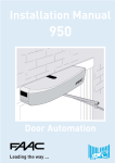
Installation Manual
820/860
Sliding Gate System
Leading the way ...
EC MACHINE DIRECTIVE COMPLIANCE DECLARATION
(DIRECTIVE 89/392 EEC, APPENDIX II, PART B)
Manufacturer: FAAC S.p.A.
Address:
Via Benini, 1
40069 - Zola Predosa
BOLOGNA - ITALY
Hereby declares that: the 820-860 automation system
• is intended to be incorporated into machinery, or to be assembled with
other machinery to constitute machinery in compliance with the requirements
of Directive 89/392 EEC, and subsequent amendments 91/368 EEC, 93/44
EEC and 93/68 EEC;
• complies with the essential safety requirements in the following EEC Directives:
73/23 EEC and subsequent amendment 93/68 EEC.
89/336 EEC and subsequent amendments 92/31 EEC and 93/68 EEC.
and furthermore declares that unit must not be put into service until the
machinery into which it is incorporated or of which it is a component has
been identified and declared to be in conformity with the provisions of
Directive 89/392 EEC and subsequent amendments enacted by the national
implementing legislation.
Bologna, 1 January 1997
Managing
Director
A. Bassi
1
IMPORTANT NOTICE FOR THE INSTALLER
GENERAL SAFETY REGULATIONS
1) WARNING! FAAC strongly recommends to follow these instructions literally for the safety of persons. Improper
installation or misuse of the product will cause very serious damages to persons.
2) Packaging material (plastic, polystyrene etc.) is a potential hazard and must be kept out of reach of children.
3) Read the instructions carefully before installing the product.
4) Keep these instructions for future reference.
5) This product has been designed and manufactured only for the use stated in this manual. Any other use not expressly
set forth will affect the reliability of the product and/or could be source of hazard.
6) FAAC S.p.A. cannot be held responsible for any damage caused by improper use or different from the use for which
the automation system is destined to.
7) Do not use this device in areas subject to explosion: the presence of flammable gas or fumes is a serious hazard.
8) Mechanical constructive elements must comply with UNI8612, CEN pr EN 12604 and CEN pr EN 12605 standards.
Countries outside the EC shall follow the regulations above besides their national normative references in order to
offer the utmost safety.
9) FAAC cannot be held responsible for failure to observe technical standards in the construction of gates and doors,
or for any deformation of the gates which may occur during use.
10) Installation must comply with UNI8612, CEN pr EN 12453 and CEN pr EN 12635.
The degree of safety of the automation must be C+E.
11) Before carrying out any operations, turn off the system’s main switch.
12) An omnipower switch shall be provided for the installation with an opening distance of the contacts of 3 mm or more.
Alternatively, use a 6A thermomagnetic breaker with multi-pole switching.
13) Ensure that there is a differential switch up-line of the electrical system, with a trip threshold of 0.03A.
14) Check that the earthing plant is in perfect condition and connect it to the metallic parts. Also earth the yellow/green
wire of the operator.
15) The automation is fitted with an anti-crush safety system that is a torque control device. In any case, further safety
devices shall be installed.
16) The safety devices (e.g. photocells, safety edges, etc.) protect areas where there is a mechanical movement
hazard, e.g. crushing, entrapment and cutting.
17) Each installation must be fitted with at least one flashing light (e.g. FAAC LAMP, MINILAMP etc.) as well as a warning
plate suitably fixed to the gate, besides the safety devices as per point 16. above.
18) FAAC cannot be held responsible regarding safety and correct functioning of the automation in the event that parts
other than FAAC original parts are used.
19) Use only FAAC original spare parts for maintenance operations.
20) Do not carry out any modifications to automation components.
21) The installer must supply all information regarding manual operation of the system in the event of an emergency
and provide the end-user with the "End-user Guide" attached to the product.
22) Keep out of persons when the product is in operation.
23) Keep out of reach of children the remote radio controls and any control devices. The automation could be
operated unintentionally.
24) The end-user must avoid any attempt to repair or adjust the automation personally. These operations must be
carried out exclusively by qualified personnel.
25) What is not explicitly stated in these instructions is not permitted.
2
AUTOMATION 820 - 860 & 826 MPS
These instructions apply to the following models:
820 EMC Z20 CR - 820 EMC - 820 EMC RF - 860 MC Z16 - 860
MC - 860 MC RF - 860 EMC Z16 - 860 EMC
The FAAC model 820 and 860 automations for sliding gates
are electromechanical operators which transmit movement
to the leaf by means of a pinion with rack or chain coupled
in an appropriate manner to the sliding gate.
The system is guaranteed to be mechanically locked
when the motor is not in operation so a lock does not need
to be installed. The gear motors have mechanical/
electronic clutches which provide the necessary adjustable
anti-crushing safety. A convenient manual release device
allows the gate to be operated in the event of a power
failure or malfunction. An electronic device allows the
open/closed limit switches to be programmed by a simple
operation without the need to weld limit switch plates. The
electronic control unit is incorporated in the gear motors.
The automations 820 - 860 & 826 MPS have been designed
and built for vehicle access control. Do not use for any
other purpose.
1. DESCRIPTION AND TECHNICAL CHARACTERISTICS
where:
Ta = opening time
Tc = closing time
Tp = pause time
Ti = interval between one complete cycle and the next.
Graph of duty cycle
Percentuale
di lav. %
% Duty cycle
% Fréquence
d'utilisation
% Benutzungsfrequenz
% Frecuencia
de utilización
100
90
80
70
60
50
40
30
20
4
1
10
2
0
3
12
Table 1
5
7
6
11
8
Fig. 1
10
햲
햳
햴
햵
햶
햷
1 2 3 4 5 6 7 8 9 10 11 12
Tempo (h) Time (h) Temps (h)
Zeit (Std.)
Tiempo (h)
Transformer
826 MPS electronic control unit
Surge capacitor
Breather/clutch adjustment screw
Electric motor
ADL electronic card
9 햸 Limit switch unit
햹
햺
햻
햽
햾
Worm screw
Crown wheel
Emergency release
Pinion
Casing
1.1.
MAXIMUM UTILISATION CURVE
The curve allows the maximum working time (T) to be
obtained as a function of duty cycle (F).
For example, the 820-860 gear motors can operate
uninterruptedly at a duty cycle of 30%.
To ensure good operation, keep to the field of operation
lying below the curve.
Important: The curve refers to a temperature of 24°C.
Exposure to direct sunlight can result in a reduction in duty
cycle to as low as 20%.
Calculating duty cycle
The duty cycle is the percentage of effective working time
(opening + closing) with respect to the total cycle time
(opening + closing + pause times).
It is calculated using the following formula:
Ta + Tc
%F =
X 100
Ta + Tc + Tp + Ti
3
Gear motor technical characteristics
MODEL
Power supply
Power consumption (W)
Reduction ratio
No. of pinion teeth
Rack
Max. thrust daN
Winding thermal protection
Duty rating
Oil quantity (l)
Type of oil
Temperature range
Gear motor weight (kg)
Housing protection
Max. gate weight (kg)
Gate speed
Max. gate length
Partial opening length
Cooling
Clutch
Housing treatment
Casing painting
Control unit
Limit switches
Deceleration
Gear motor dimensions LxHxD (mm)
Model
Motor speed (rpm)
Power consumption (W)
Current draw (A)
Surge condenser
Power supply
820
860
230 V (+6% -10%)
400
600
1:30
Z 16 / Z 20
4 module pitch 12.566
50
110
135 °C
30% (see graph)
0,800
FAAC XD 220
-20 to +55°c
14
15
IP 44
600
1200
12 m/min
9,6 m/min
13 m
10 m
1,60 m
1,20 m
self-ventilated
single disc in oil bath
cataphoresis
polyester RAL 7042
826 MPS (incorporated)
programmable memory (ADL)
electronic
see Fig. 3
Electric motor technical specifications
820
860
1400
1400
400
600
2
3
20 µF
30 µF
230 V (+6 -10%) 50 Hz
165
40
2. ELECTRICAL SET-UP (standard system)
0¸ 50
Fig. 4
햲
햳
햴
햵
햶
165
40
235
820/860 operator with
826 MPS control unit
Photocells
Key switch
Flashing light
Radio receiver
0¸ 50
Fig. 2
235
Fig. 5
accessories and the electricity supply as described in
section 2. For ease of connection, ensure that the
cables protrude by about 45 cm from the hole in the
base plate.
3. DIMENSIONS
140
221,2
Values are expressed in mm.
Fig. 3
Fig. 6
4. INSTALLING THE AUTOMATION
53
N.B.: It is advisable to install the base plate on a concrete
base raised about 50 mm from the ground (Fig. 7).
2) Assemble the foundation plate as shown in Fig. 6.
3) Prepare a foundation plinth as shown in Fig. 8 and install
the base plate providing one or more conduits for
electrical cables. Use a level to check that the plate is
perfectly horizontal and wait for the cement to set.
4) Set up the electrical cables for connection to the
13
50
• The gate’s structure must be suitable for automation.
Take special care to ensure that the wheels are large
enough to support the full weight of the gate, that a
top runner is installed and that mechanical limit stops
are fitted to prevent the gate from coming off the
runner.
• The characteristics of the ground must ensure sufficient
support for the foundation plinth.
• There must be no pipes or electrical cables in the area
to be dug for installing the foundation plinth.
• If the gear motor is located in a vehicle transit area, it
is a good idea to provide protection against accidental
collisions.
• Check that the gear motor has an efficient earth
connection.
4.2.
INSTALLING THE BASE PLATE
1) The base plate must be positioned as shown in Fig. 4
(right-handed closure) or Fig. 5 (left-handed closure) to
ensure that the pinion and rack mesh correctly.
Z20 131 mm (820)
Z16 123 mm (860)
4.1.
PRELIMINARY CHECKS
For safe, correct operation of the automation, make sure
that the following requirements are met:
221,2
Fig. 7
4.3.
MECHANICAL INSTALLATION
1) With the aid of a Teflon hammer insert the adjustable
feet into the hexagonal holes under the base of the
gear motor as shown in Fig. 9.
2) Remove the casing and position the gear motor on the
foundation plate, threading the electrical cables into
the conduit in the operator body.
3) Adjust the height of the feet and the distance from the
gate as shown in Fig. 7.
4) Secure the gear motor onto the base plate using the
two nuts and the plates provided as shown in Fig. 10.
5) Set up the operator for manual operation as described
in section 6.
6) Remove the breather screw as shown in Fig. 11 and
keep it in a safe place.
4
Fig. 12
3) Rest the first rack element level on the pinion and weld
the threaded pawl onto the gate as shown in Fig. 15.
4) Slide the gate manually making sure that the rack rests
on the pinion. Weld the second and third pawls.
5) Place another rack element next to the first and use a
section of rack to set the teeth of the two elements in
phase as shown in Fig. 16.
6) Open the gate manually and weld the three threaded
pawls. Proceed in this manner until the entire gate has
been covered.
Fig. 8
4.4.2.
SCREW-ON STEEL RACK (Fig. 13)
2
Fig. 13
1
1) Slide the leaf manually to the closed position.
2) Rest the first rack element level on the pinion and insert
the spacer in the upper part of the slot between the
rack and the gate.
3) Mark the point to be drilled on the gate. Drill a 6.5 mm
diameter hole and thread using 8 mm screw taps.
Tighten the bolt.
4) Slide the gate manually making sure that the rack rests
on the pinion and repeat the operations of point 3.
5) Place another rack element next to the first and use a
section of rack to set the teeth of the two elements in
phase as shown in Fig. 16.
6) Slide the gate manually and secure the rack element
in the same manner as the first element. Proceed in this
manner until the entire gate has been covered.
Fig. 9
Fig. 10
Fig. 14
4.4.3. SCREW-ON NYLON RACK (Fig. 14)
Fig. 11
4.4.
MOUNTING THE RACK
4.4.1.
WELD-ON STEEL RACK (Fig. 12)
1) Mount the three threaded pawls on the rack element,
positioning them in the upper part of the slot. This way
the play provided by the slot will allow for future
adjustment.
2) Slide the leaf manually to the closed position.
5
1) Move the leaf manually to the closed position.
2) Rest the first rack element level on the pinion and mark
the point to be drilled on the gate. Drill a 4 mm
diameter hole and screw on the 6x20 mm self-tapping
screw with reinforcement plate.
3) Move the gate manually making sure that the rack rests
on the pinion and repeat the operations of point 2.
4) Place another rack element next to the first using a
section of rack to set the teeth of the two elements in
phase as shown in Fig. 16.
5) Move the gate manually and carry out the fixing
operations the same way as for the first element. Proceed
in this manner until the entire gate has been covered.
Fig. 15
Fig. 19
4.5.2
Fig. 16
7
2
1
1.5
N.B.: Check that none of the rack elements come off the
pinion during the movement of the gate.
Important: Do not weld the rack elements either to the
spacers or to each other (for steel rack only).
After installing the rack, lower the position of the gear motor
by adjusting the feet (Fig. 17) by about 1.5 mm to ensure
correct meshing with the pinion.
MODEL 820 EMC RF - 860 MC RF (figs. 20-21)
- Insert the elastic pin 7 in the shaft with the aid of a
hammer.
- Fit the chain pinion on the shaft by matching up the
pinion seats with the elastic pin and tighten up screw 4
and washers 5 and 6.
- Fit the idle transmission bracket on the gear motor flange,
removing the four upper bolts and replacing them with
the 5x12 hex bolts 1 and washers 2 in the kit as shown in
Fig. 20.
- Fit the chain as shown in Fig. 21 and mount the casing with
screws 1 and washers 3 (Fig. 20).
6
5
4
3 1
Fig. 20
Fig. 17
Check manually that the gate reaches the mechanical
travel limits correctly and that it does not encounter
friction during its travel.
Do not use grease or other lubricants between the pinion
and the rack.
4.5.
MOUNTING CHAIN PINIONS
In versions for chain and idle transmission applications,
mount the Z16 or Z20 chain pinion. Proceed as follows:
4.5.1
MODEL 820 EMC - 860 MC - 860 EMC (figs. 18-19)
- Insert the elastic pin in the shaft with the aid of a hammer.
- Fit the chain pinion on the shaft by matching up the pinion
seats with the elastic pin and tighten up the screw with the
washers.
Fig. 18
Fig. 21
5. START-UP
5.1.
CONNECTION TO ELECTRONIC CONTROL UNIT
Warning: Always turn off the electricity supply before
carrying out any work on the electronic control unit
(connections, programming, maintenance).
Warning: When terminal board J2 is disconnected, high
voltage remains on the outputs of the capacitor, motor and
transformer power supplies.
Observe points 10, 11, 12, 13 and 14 in the GENERAL SAFETY
INSTRUCTIONS.
As shown in Fig. 2, prepare the conduits and make the
electrical connections from the 826 MPS electronic control
unit to the chosen accessories.
6
5.1.2.
Always route the power supply cables separately from the
control and safety cables (keyswitch, receiver, photocells,
etc.). Use separate conduits to avoid any interference.
OPEN
A/C
STOP
FX
-
230 V (+6 -10%) 50 Hz
600 W
500 mA
5 W (24Vac)
- 20°C + 55°C
1
2
3
4
5
- +
6
7
8
9
11 12
10
FAAC
LAMP
4
FX1
1
TABLE3 ACCESSORIES CURRENT DRAW
3
CONTATTO COSTA DI SICUREZZA
SAFETY EDGE CONTACT
CONTACT TRANCHE DE SÉCURITÉ
KONTAKT SICHERHEITSKANTE
CONTACTO BANDA DE SEGURIDAD
230 V
+6% -10%
50-60 Hz
5
LAMP
24V 3W
13 14
2
TABLE 2 TECHNICAL CHARACTERISTICS OF 826 MPS
POWER SUPPLY
MAX. MOTOR LOAD
MAX. ACCESSORIES LOAD
MAX. WARNING LAMP POWER
TEMPERATURE RANGE
ELECTRICAL CONNECTIONS
4
FX2
3
2
5
1
2
NOMINAL CURRENT DRAW
50mA
20mA
6mA
20mA / 55mA
12mA / 6mA
15mA
15mA
90mA
50mA
70mA
1
2
1
TYPE OF ACCESSORY
R 31
PLUS 433 E
MINIDEC SL / DS
DECODER SL / DS
RP 433 ESL / EDS
DIGICARD
METALDIGIKEY
FOTOSWITCH
DETECTOR F4 / PS6
MINIBEAM
Fig. 23a
5.2.
DESCRIPTION OF TERMINAL BLOCK
5.2.1. OPEN (terminals 1-2)
5.1.1. 826 MPS CONTROL UNIT
J3
FAAC
J8
This means any control device with a N.O. contact which
causes the gate to open when activated. In automatic
and semiautomatic logics it is active for both opening and
closure.
J7
826MPS
P3
P2
P1
5.2.2.
LD5 LD6 LD7 LD8
F2
DECODER
1 2 3 4 5 6 7 8
J1
LD1 LD2
LD3 LD4
5.2.3.
DS1
J9
2
3
4
J6
J5
5.2.4. SAFETY FX (terminals 5 - 6)
J2
5
6
7
8
9 10
11 12
13
14
MOTOR
This means all devices (photocells, safety edges, magnetic
loops) with a N.C. contact which stop the movement of
the gate when an obstacle is present in the area protected
by the safety devices.
N.B.: If stop devices are not connected, jumper terminals 5-6.
CAP
.
Fig. 22
Table 4
LD1
LD2
LD3
LD4
LD5
LD6
LD7
LD8
P1
P2
P3
J1
J2
J3
J4
J5
J6
J7
J8
J9
F1
F2
DS1
STOP (terminals 1-4)
This means a control device with a N.C. contact which
causes the gate status (opening-pause-closure) to be
interrupted until the next impulse is sent.
N.B.: If stop devices are not connected, jumper terminals 1-4.
F1
J4
1
A/C (terminals 1-3)
This means any control device with a N.O. contact which
causes partial opening of the gate when activated in E1,
E2, A1, A2, S1 and S2 logics. In B and C logics it causes the
gate to close.
826 MPS control unit components
OPEN LED
PARTIAL OPEN/CLOSE LED
STOP LED
SAFETY LED
LIMIT SWITCH ALARM LED
OPENING LIMIT SWITCH LED
CLOSURE LIMIT SWITCH LED
SLIDING SPEED LED
OPENING LIMIT SWITCH PROGRAMMING BUTTON
CLOSURE LIMIT SWITCH PROGRAMMING BUTTON
LIMIT SWITCH / RESET PROGRAMMING BUTTON
DECODER CONNECTOR
LOW VOLTAGE TERMINAL BLOCK
ADL CONNECTOR
FAAC LAMP OUTPUT TERMINAL BLOCK
CAPACITOR CONNECTOR
ELECTRIC MOTOR CONNECTOR
TRANSFORMER PRIMARY CONNECTOR
TRANSFORMER SECONDARY CONNECTOR
230 Vac POWER SUPPLY TERMINAL STRIP
ELECTRIC MOTOR FUSE (F 5 A)
ACCESSORIES FUSE (T 1.6 A)
PROGRAMMING DIPSWITCH
5.2.5.
+ - LOW VOLTAGE POWER SUPPLY (terminals 6 - 7)
These are the 24 Vdc terminals to which the accessories
must be connected.
Proceed as shown in Table 3 in order not to exceed the
maximum permitted load.
5.2.6.
LAMP (terminals 8 - 9 - 10)
These are the 24 Vac terminals to which the warning lamp
must be connected.
Warning lamp operation illustrated in Fig. 24 refers to
connection to terminals 8-9. Connecting the warning
lamp to terminals 8-10 gives inverse operation.
5.2.7.
FAAC LAMP (terminals 11 - 12)
These are the 230 Vac terminals to which the flashing light
must be connected.
5.2.8.
230 V MAINS SUPPLY (terminals 13 - 14)
These are the terminals to which the 230 Vac electricity
supply must be connected.
Connect the earth cable to the post as shown in Fig. 23b.
5.2.9.
BEHAVIOUR OF SAFETY DEVICES
The safety devices operate during closure only. In A1, E1
and S1 logics, interrupting the safety device contacts causes
the gate to stop closing and start opening immediately. In
7
5.4.
OPERATION IN VARIOUS LOGICS
TABLE 5 LOGIC E1 (SEMIAUTOMATIC)
IMPULSES
LOGIC E1
GATE STATUS
CLOSED
OPEN
CLOSING
OPENING
STOPPED
STOP
no effect
no effect
stops
stops
no effect
OPEN - A/C (1) opens (2)
recloses (2
inverts motion
stops
recloses (reopens when safety
devices are engaged) (2)
SAFETY
no effect
no effect
inverts motion
no effect
no effect
TABLE 6 LOGIC E2 (SEMIAUTOMATIC)
IMPULSES
LOGIC E2
Fig. 23b
A2, E2 and S2 logics interrupting the safety device contacts
causes the gate to stop closing, then to start opening again
when the safety devices are released.
5.2.10. ELECTRONIC SAFETY DEVICE
(models 820 EMC - 860 EMC only)
The operator is equipped with a system which cuts in when
it senses a 20% reduction in pinion speed. The device inverts
the closing movement and inhibits opening movement.
When this safety device cuts in, LED S goes out for a few
seconds. Automatic re-closure is inhibited if the electronic
anti-crushing safety has cut in.
5.3.
DIPSWITCH SETTINGS
N.B.: PRESS THE RESET BUTTON AFTER ALL PROGRAMMING
OPERATIONS
Logic
GATE STATUS
CLOSED
OPEN
CLOSING
OPEN -A/C(1)opens (2)
recloses (2)
inverts motion
STOP
no effect
no effect
stops
OPENING
STOPPED
stops
recloses (reopens when
safety devices are
engaged) (2)
stops
no effect
TABLE 7 LOGIC A1 (AUTOMATIC)
LOGIC A1
GATE STATUS
CLOSED
STOP
no effect
SAFETY
no effect
OPEN
stops counting
CLOSING
OPENING
STOPPED
inverts motion
no effect
recloses (2)
stops
stops
no effect
freezes pause until
disengagement
inverts motion
no effect
no effect
TABLE 8 LOGIC A2 (AUTOMATIC)
LOGIC A2
SW1 SW2 SW3
E1
ON
ON
OFF
ON
ON
S2
ON
OFF
ON
S1
OFF OFF
ON
B
ON
ON
OFF
5
15
ON
ON
C
OFF
ON
OFF
10
30
OFF
ON
E2
ON
OFF OFF
30
60
ON
OFF
A2
OFF OFF OFF
120
180
OFF OFF
ON
Pause time (sec) (1)
Logic
A1 A2 S2
S1 SW4 SW5
STOP
no effect
SAFETY
no effect
OPEN
CLOSING
stops counting
stops
OPENING
STOPPED
no effect
recloses (2)
stops
no effect
recloses after 5 s
stops and inverts motion
when disengaged (2)
no effect
no effect
TABLE 9 LOGIC S1 (SAFETY)
OPEN
2
3
4
5
6
7
IMPULSES
OPEN - A/C (1) opens and recloses after
pause time (2)
recloses after 5 s (3)
inverts motion
LOGIC S1
GATE STATUS
CLOSED
1
IMPULSES
OPEN - A/C (1) opens and recloses after
pause time (2)
recloses after 5 s (3)
GATE STATUS
CLOSED
A1
SAFETY
no effect
no effect
stops and inverts motion
when disengaged (2)
no effect
no effect
8
CLOSING
OPENING
STOPPED
IMPULSES
OPEN - A/C (1) opens and recloses after
pause time (2)
recloses immediately
(2 and 3)
inverts motion
inverts motion
recloses (2)
STOP
no effect
SAFETY
no effect
stops counting
recloses after 5 s
stops
stops
no effect
inverts motion
no effect
no effect
TABLE 10 LOGIC S2 (SAFETY)
Gate closure direction as viewed from inside
To right
To left
SW8
ON
OFF
LOGIC S2
GATE STATUS
CLOSED
CLOSING
OPENING
STOPPED
inverts motion
recloses (2)
OPEN
Pre-flashing (2)
Yes
No
SW7
ON
OFF
Warning light operation (3)
ON
OFF
Closed
Opening/Open
Off
Steady light
STOP
no effect
SAFETY
no effect
stops counting
freezes pause until
disengagement
stops and inverts motion
when disengaged (2)
no effect
no effect
stops
stops
no effect
TABLE 11 LOGIC B (SEMIAUTOMATIC)
Gate status
SW6
IMPULSES
OPEN - A/C (1) opens and recloses after
pause time (2)
recloses immediately
(2 and 3)
inverts motion
Closing
Steady light
Flashing
(1) Pause times include pre-flashing.
(2) Pre-flashing commences 5 seconds before the start of each
movement.
(3) Warning light connected between 8 and 9 (if connected
between 8 and 10, operation is inverted).
Fig. 24
LOGIC B
GATE STATUS
CLOSED
OPEN
CLOSING
OPENING
STOPPED
8
IMPULSES
OPEN
A/C (5)
opening (2)
no effect
no effect
no effect
completes
opening (2)
no effect
closing (2)
no effect
no effect
completes
opening (2)
SAFETY (until
disengagement)
no effect
inhibits closing
stops
no effect
inhibits closing
STOP
no effect
no effect
stops movement
stops movement
no effect
TABLE 12 LOGIC C (DEADMAN)
LOGIC C
IMPULSES
GATE STATUS
OPEN (4)
A/C (4 and 5)
CLOSED
OPEN
CLOSING
OPENING
STOPPED
opens
no effect
no effect
no effect
closes
no effect
completes opening completes closing
SAFETY (until
disengagement)
no effect
inhibits closing
stops
no effect
inhibits closing
STOP
no effect
no effect
stops
stops
no effect
(1) The A/C input enables partial opening.
(2) With pre-flashing selected movement starts after 5
seconds.
(3) If the impulse is sent after pre-flashing the timer recounts.
(4) For operation in C logic keep the pushbutton depressed.
Movement stops upon release.
(5) The A/C input controls closure.
5.5.
PROGRAMMING LIMIT SWITCHES
IMPORTANT: CHECK THE LENGTH OF THE GATE. THE
OPERATOR HAS A LIMIT SWITCH SYSTEM WHICH ALLOWS
FOR AUTOMATION OF GATES WITH A MAXIMUM LENGTH OF
13 m FOR MODELS 820 (Z 20 PINION) AND 10 m FOR
MODELS 860 (Z 16 PINION).
FAILURE TO OBSERVE THESE RECOMMENDATIONS WILL
ADVERSELY AFFECT OPERATION OF THE ADL LIMIT SWITCH.
1) To facilitate installation, it is advisable to program the
control unit in E1 logic (semi-automatic) by positioning
the relative dipswitches as follows:
SW1 - SW2 - SW3 to ON.
It is also advisable to inhibit pre-flashing by positioning
dipswitch SW7 to OFF.
Fig. 26
7) Without moving the gate carry out the following
operations on the 826 MPS control unit (Fig. 27) in the
stated order:
a) hold down FCA.
b) press the RESET button for about 1 second. The ADL
LED will light up for approximately one second to
confirm that the limit switch has been recognised.
c) release the FCA button.
RESET
FCC
FCA
Fig. 27
SW8 OFF
SW8 ON
Fig. 25
2) Position dipswitch SW8 according to the direction in
which the gate closes (see Fig. 25) (Rack application).
IMPORTANT: In chain applications the dipswitch SW8 must
be positioned to ON for closure to left and OFF for closure
to right.
The positions of dipswitches SW4, SW5 and SW6 have no
effect.
3) Move the gate manually to its mid-travel position.
4) Switch on the electricity supply to the system and
check that the status of the LEDs is as follows:
LED ON
LED OFF
ADL - FCA - FCC
S (860) - STOP - FSW
OPEN - A/C S (820)
8) Wait for a few seconds, then slide the gate manually
until it is a few centimetres from the closed position end
stop.
9) Without moving the gate carry out the following
operations on the 826 MPS control unit (fig. 27) in the
stated order:
a) hold down FCC.
b) press the RESET button for about 1 second. The ADL
LED will light up for approximately one second to
confirm that the limit switch has been recognised.
c) release the FCC button.
10)Re-engage the operator by sliding the gate until the
release device engages.
11)Send an open impulse and check that the gate opens,
performs a brief deceleration, then stops at the
programmed open position limit switch.
12)Send another impulse and check that the gate closes.
13)To modify limit switch settings, repeat the sequence of
operations from point 3) to point 12).
IMPORTANT: If the LED starts flashing quickly (0.25 s) during
the limit switch setting operations, follow the instructions
given in the ALARM CONDITIONS section.
IMPORTANT: MAKE SURE THAT THE GATE IS AT ITS MIDTRAVEL POSITION.
5) Remove the safety tab as illustrated in Fig. 26 and keep
it for future maintenance work.
6) Open the gate until it is just a few centimetres away
from the open position end stop.
9
N.B.: Any interruption in the power supply will not affect
memorisation of the limit switch positions.
If during a manual operation the gate is moved beyond
the memorised limit switch positions, a series of open
impulses must be sent to move the gear motor to the zone
of normal operation.
5.6.
OPERATION OF ADL LIMIT SWITCH
The ADL limit switch detects the number of pinion rotations
by means of a toothed belt transmission.
The operator is supplied with the drive in idle and the ADL
system positioned in the mid-travel position. Removing the
safety tab engages the transmission.
IMPORTANT: If the tab has already been removed by
mistake, thereby losing the centre-scale position of the
ADL, the following steps must be carried out to restore the
start condition:
1) Release the operator.
2) Slide the gate manually to the mid-travel position.
3) Remove the rack element so as to free the pinion.
4) Turn the pinion by hand clockwise or, if the pinion
becomes hard to turn, anticlockwise until the ADL
(centre scale) LED lights up continuously.
5.7.
ALARM CONDITIONS
The ADL LED flashes in the following cases:
1) ADL system overrun.
2) Incorrect position of dipswitch SW8.
3) ADL connector removed.
4) Opening/closure time longer than 120 seconds.
The warning light (if connected) flashes at the same time
as the ADL LED.
While this condition is active all the control unit functions
are inhibited. It is possible to return to normal conditions
only after eliminating the cause of the alarm and pressing
the RESET button on the control unit.
N.B.: When the warning light flashes with the ADL LED off,
this means that fuse F2 has blown.
5.8.
REGULATING THE TRANSMITTED TORQUE
To regulate the transmitted torque turn the screw on the
electric motor shaft (Fig. 11).
To increase the torque, turn the screw clockwise.
To reduce the torque, turn the screw anticlockwise.
IMPORTANT: THE OPERATOR IS DELIVERED WITH THE CLUTCH
SET TO MAXIMUM, SO THE SCREW MUST BE TURNED
ANTICLOCKWISE TO REACH THE OPTIMAL SETTING.
Activate the operator and stop the gate manually to
check that the clutch engages. Bear in mind that when
this is done with model 820 the electronic anti-crushing
device cuts in and stops the movement of the gate if it is
opening and reverses it if it is closing.
The electronic anti-crushing device activation threshold
depends on the setting of the mechanical clutch.
5.9
TESTING THE AUTOMATION
When installation is complete, affix the danger warning
label to the top of the casing (Fig. 28). Thoroughly check
operation of the automation and all connected
accessories.
Give the customer the User Guide. Explain correct use and
operation of the gear motor and draw attention to the
potential danger zones of the automation.
6. MANUAL OPERATION
If it is necessary to operate the gate manually due to a
power failure or malfunction of the automation, operate
on the release device as follows.
LEVER RELEASE DEVICE (Fig. 29)
- Remove the release device rubber cap.
- Insert the lever provided into the triangular slot release
system and turn clockwise by about half a revolution.
- Open or close the gate manually.
Fig. 28
NUMBERED KEY RELEASE CAP (Fig. 30).
- Open the lock protection flap.
- Insert the key into the lock and turn.
- Turn the release cap anticlockwise.
- Perform the gate opening or closing operation manually.
- Turn the release cap anticlockwise.
7. RETURN TO NORMAL OPERATION
To prevent an accidental impulse from activating the
gate during the operation, turn off the electricity supply to
the system before relocking the operator.
LEVER RELEASE DEVICE (Fig. 29)
- Insert the lever provided into the triangular slot release
device and turn anticlockwise by about half a revolution.
- Refit the release device rubber cap
- Move the gate until the release device engages.
NUMBERED KEY RELEASE CAP (Fig. 30).
- Open the lock protection flap.
- Insert the key into the lock and turn.
- Turn the release cap anti-clockwise.
- Move the gate until the release device engages.
8. MAINTENANCE
When performing maintenance always check that the
anti-crushing clutch is correctly regulated and that the
safety devices operate correctly.
8.1.
TOPPING UP WITH OIL
Check the quantity of oil in the operator periodically.
For medium-low duty cycles an annual check is sufficient;
for more intense use it is advisable to check every 6
months.
The level must not fall below the reference notch on the
dipstick attached to the oil filler cap (Fig. 31).
To top up, unscrew the filler cap (Fig. 31) and pour in oil up
to the correct level. Use exclusively FAAC XD 220 oil.
9.
REPAIRS
For repairs contact an authorised FAAC Repair Centre.
10.
ACCESSORIES AVAILABLE
10.1 CORD-OPERATED MANUAL RELEASE
If the gear motor is installed in an inconvenient position, it
is advisable to use the accessory shown in Fig. 32 to
perform the release operation. Pulling on cord A releases
the system, whereas pulling on cord B relocks the gear
motor.
Important: When the automation is reset, move the gate
until the release device engages before sending a control
impulse.
10
2
1
Fig. 30
Fig. 29
OIL
B
A
Fig. 32
Fig. 31
11
USER’S GUIDE
820 - 860 AUTOMATION
Read the instructions carefully before using the product
and keep them for future reference.
GENERAL SAFETY INSTRUCTIONS
If correctly installed and operated, the 820-860 automations
ensure a high level of safety.
However, some simple rules should be followed to avoid
accidents:
- Do not stand in the vicinity of the automation or allow
anyone else, especially children, to do so and do not
place objects in the vicinity of the automation. This is
particularly important during operation.
- Keep remote controls or any other control device out of
the reach of children to prevent them from accidentally
operating the automation.
- Do not allow children to play with the automation.
- Do not deliberately obstruct the movement of the gate.
- Make sure that branches or bushes do not interfere with
the movement of the gate.
- Keep the luminous signalling systems efficient and clearly
visible.
- Do not attempt to operate the gate manually without
first releasing it.
- In the event of a malfunction, release the gate to allow
access and call a qualified technician for service.
- After setting manual operation, disconnect the electricity
supply from the system before returning to normal
operation.
- Do not make any modifications to components belonging
to the automation system.
- Do not attempt to perform any repair work or tamper with
the automation. Call FAAC qualified personnel for repairs.
- At least once every six months have the automation, the
safety devices and the earth connection checked by a
qualified technician.
DESCRIPTION
The FAAC 820 - 860 automations are ideal for controlling
vehicle access areas with medium-high transit frequencies.
The 820 and 860 for sliding gates are electromechanical
operators which transmit movement to the leaf by means
of a pinion with rack or chain coupled in an appropriate
manner to the sliding gate.
If automatic operation has been selected, sending an
impulse causes the gate to reclose on its own after the
selected pause time.
If semiautomatic operation has been selected, a second
impulse must be sent to reclose the gate.
An opening impulse send while the gate is reclosing
causes it to change direction of movement.
A stop command (if available) stops movement at any time.
For detailed information on operation of the sliding gate
in the various operating modes, contact the installation
technician.
The automations have safety devices (photocells) which
prevent the gate from reclosing when an obstacle lies
within the area they are protecting.
The system ensures mechanical locking when the motor is
not in operation, so it is not necessary to install a lock.
For this reason the release system must be used for manual
opening.
The gear motors have mechanical/electronic clutches
which offer the necessary anti-crushing safety. An
electronic device allows the open/closed limit switch
positions to be programmed. The electronic control unit is
incorporated in the gear motors.
A convenient manual release device allows the gate to
be operated in the event of a power failure or malfunction.
The light flashes while the gate is moving.
MANUAL OPERATION
If the gate has to be operated manually due to a power
failure or malfunction of the automation, use the release
device as follows.
LEVER RELEASE DEVICE (Fig. 1)
- Remove the release device rubber cap.
- Insert the lever provided into the triangular slot release
system and turn clockwise by about 1/2 a revolution.
- Open or close the gate manually.
NUMBERED KEY RELEASE CAP (Fig. 2)
- Open the lock protection flap.
- Insert the key in the lock and turn.
- Turn the release cap clockwise.
- Open or close the gate manually.
RETURN TO NORMAL OPERATION
To prevent an accidental impulse from activating the
gate during the operation, turn off the electricity supply to
the system before relocking the operator.
LEVER RELEASE DEVICE (Fig. 1)
- Insert the lever provided into the triangular slot release
device and turn anticlockwise by about half a revolution.
- Refit the release device rubber cap.
- Move the gate until the release device engages.
NUMBERED KEY RELEASE CAP (Fig. 2).
- Open the lock protection flap.
- Insert the key into the lock and turn.
- Turn the release cap anti-clockwise.
- Move the gate until the release device engages.
Fig. 1
2
1
Fig. 2
23
12
The descriptions and illustrations contained in this manual are not
binding. FAAC reserve the right, whilst leaving the main features of
the main equipment unaltered, to undertake any modifications it holds
necessary for either technical or commercial reasons, at any time and
without revising the present publication.
FAAC (UK) Limited, 6 Hamilton Close
Houndmills Estate, Basingstoke, RG21 6YT
Telephone: 01256 318100
Fax: 01256 318101
Email: [email protected]
Website: www.faac.co.uk
V5 01/07
Your authorised FAAC dealer