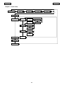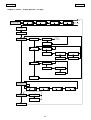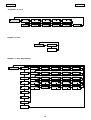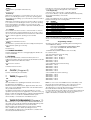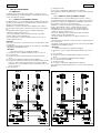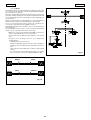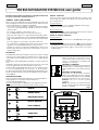
1
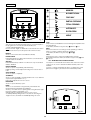
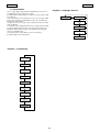
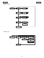
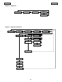
Installation Manual
950
Door Automation
Leading the way ...
Fig. 2a
1
2
2
Fig. 2b
Fig. 3
3
4
Fig. 4a
3
1
6
2
5
Fig. 4
Fig. 4b
1
Fig.5
Fig.6
Tav.A: MONTAGGIO SULL’ARCHITRAVE (BRACCIO ARTICOLATO A SPINGERE) · TABLE A: LINTEL MOUNTING (PUSHING ARTICULATED ARM)
SCHÉMA A: MONTAGE SUR LE LINTEAU (BRAS ARTICULÉ Á POUSSER) · ÜBERSICHT A: STURZEINBAU (DRÜCK-GELENKARM)
LÁM. A: MONTAJE EN EL DINTEL (BRAZO ARTICULADO DE EMPUJE)
Piano di foratura · Drilling template · Schéma de perçage · Bohrbild · Plano de perforación
(*) Quota con albero standard.
Nel caso fosse necessario aumentare
la distanza tra l’operatore ed il
braccio, utilizzare le prolunghe
modulari opzionali.
Ciacuna prolunga aumenta il valore
di altezza standard di 30 mm. E’
suggeribile non montare più di 2
prolunghe .
(*) Distance with standard extension.
If a greater distance between the
operator and the arm is required,
add the optional modular
extensions.
Each modular extension increases
the standard height of 30 mm. It’s
advisable not to place more then
2 extensions.
(*) Quota con albero standard.
Nel caso fosse necessario aumentare
la distanza tra l’operatore ed il
braccio, utilizzare le prolunghe
modulari opzionali.
Ciacuna prolunga aumenta il valore
di altezza standard di 30 mm. E’
suggeribile non montare più di 2
prolunghe .
(*) Cote avec arbre standard.
Dans le cas d’installation
nécessitant une plus grande
distance entre l’opérateur et le
bras, utiliser les rallonges
modulaires en option.
Chaque rallonge augmente la
hauteur standard de 30 mm. Il est
conseillé de ne pas monter plus
de 2 rallonges.
(*) Cota con eje estándar.
Si fuera necesario aumentar la
distancia entre el actuador y el
brazo, utilizar las prolongaciónes
modulares opcionales.
Cada prolungación aumenta la
altura del eje de 30 mm. Se
recomanda de no instalar mas de
2 prolongaciónes modulares.
Quote in mm · Dimensions in mm · Cotes en mm · Maßangaben in mm · Cotas en mm
Tav.B : MONTAGGIO SULLA PORTA (BRACCIO ARTICOLATO A SPINGERE) · TABLE B: DOOR MOUNTING (PUSHING ARTICULATED ARM)
SCHÉMA B: MONTAGE SUR LA PORTE (BRAS ARTICULÉ Á POUSSER) · ÜBERSICHT B: TÜREINBAU (DRÜCK-GELENKARM)
LÁM. B: MONTAJE EN LA PUERTA (BRAZO ARTICULADO DE EMPUJE)
Piano di foratura · Drilling template · Schéma de perçage · Bohrbild · Plano de perforación
(*) Quota con albero standard.
Nel caso fosse necessario aumentare
la distanza tra l’operatore ed il
braccio, utilizzare le prolunghe
modulari opzionali.
Ciacuna prolunga aumenta il valore
di altezza standard di 30 mm. E’
suggeribile non montare più di 2
prolunghe .
(*) Distance with standard extension.
If a greater distance between the
operator and the arm is required,
add the optional modular
extensions.
Each modular extension increases
the standard height of 30 mm. It’s
advisable not to place more then
2 extensions.
(*) Quota con albero standard.
Nel caso fosse necessario aumentare
la distanza tra l’operatore ed il
braccio, utilizzare le prolunghe
modulari opzionali.
Ciacuna prolunga aumenta il valore
di altezza standard di 30 mm. E’
suggeribile non montare più di 2
prolunghe .
(*) Cote avec arbre standard.
Dans le cas d’installation
nécessitant une plus grande
distance entre l’opérateur et le
bras, utiliser les rallonges
modulaires en option.
Chaque rallonge augmente la
hauteur standard de 30 mm. Il est
conseillé de ne pas monter plus
de 2 rallonges.
(*) Cota con eje estándar.
Si fuera necesario aumentar la
distancia entre el actuador y el
brazo, utilizar las prolongaciónes
modulares opcionales.
Cada prolungación aumenta la
altura del eje de 30 mm. Se
recomanda de no instalar mas de
2 prolongaciónes modulares.
Quote in mm · Dimensions in mm · Cotes en mm · Maßangaben in mm · Cotas en mm
Tav.C
: MONTAGGIO SULL’ARCHITRAVE (BRACCIO A PATTINO L=330mm) · Table A: LINTEL MOUNTING (SLIDING ARM L=330mm)
Schéma A: MONTAGE SUL LE LINTEAU (BRAS Á PATIN L=330mm) · Übersicht A: STURZEINBAU (GLEITARM L=330mm)
Lám. A: MONTAJE EN EL DINTEL (BRAZO CON PATÍN L=330mm)
Piano di foratura · Drilling template · Schéma de perçage · Bohrbild · Plano de perforación
(*) Quota con albero standard.
Nel caso fosse necessario aumentare
la distanza tra l’operatore ed il
braccio, utilizzare le prolunghe
modulari opzionali.
Ciacuna prolunga aumenta il valore
di altezza standard di 30 mm. E’
suggeribile non montare più di 2
prolunghe .
(*) Distance with standard extension.
If a greater distance between the
operator and the arm is required,
add the optional modular
extensions.
Each modular extension increases
the standard height of 30 mm. It’s
advisable not to place more then
2 extensions.
(*) Quota con albero standard.
Nel caso fosse necessario aumentare
la distanza tra l’operatore ed il
braccio, utilizzare le prolunghe
modulari opzionali.
Ciacuna prolunga aumenta il valore
di altezza standard di 30 mm. E’
suggeribile non montare più di 2
prolunghe .
(*) Cote avec arbre standard.
Dans le cas d’installation
nécessitant une plus grande
distance entre l’opérateur et le
bras, utiliser les rallonges
modulaires en option.
Chaque rallonge augmente la
hauteur standard de 30 mm. Il est
conseillé de ne pas monter plus
de 2 rallonges.
(*) Cota con eje estándar.
Si fuera necesario aumentar la
distancia entre el actuador y el
brazo, utilizar las prolongaciónes
modulares opcionales.
Cada prolungación aumenta la
altura del eje de 30 mm. Se
recomanda de no instalar mas de
2 prolongaciónes modulares.
Quote in mm · Dimensions in mm · Cotes en mm · Maßangaben in mm · Cotas en mm
Tav.D
: MONTAGGIO SULL’ARCHITRAVE (BRACCIO A PATTINO L=430mm) · Table A: LINTEL MOUNTING (SLIDING ARM L=430mm)
Schéma A: MONTAGE SUL LE LINTEAU (BRAS Á PATIN L=430mm) · Übersicht A: STURZEINBAU (GLEITARM L=430mm)
Lám. A: MONTAJE EN EL DINTEL (BRAZO CON PATÍN L=430mm)
Piano di foratura · Drilling template · Schéma de perçage · Bohrbild · Plano de perforación
(*) Quota con albero standard.
Nel caso fosse necessario aumentare
la distanza tra l’operatore ed il
braccio, utilizzare le prolunghe
modulari opzionali.
Ciacuna prolunga aumenta il valore
di altezza standard di 30 mm. E’
suggeribile non montare più di 2
prolunghe .
(*) Distance with standard extension.
If a greater distance between the
operator and the arm is required,
add the optional modular
extensions.
Each modular extension increases
the standard height of 30 mm. It’s
advisable not to place more then
2 extensions.
(*) Quota con albero standard.
Nel caso fosse necessario aumentare
la distanza tra l’operatore ed il
braccio, utilizzare le prolunghe
modulari opzionali.
Ciacuna prolunga aumenta il valore
di altezza standard di 30 mm. E’
suggeribile non montare più di 2
prolunghe .
(*) Cote avec arbre standard.
Dans le cas d’installation
nécessitant une plus grande
distance entre l’opérateur et le
bras, utiliser les rallonges
modulaires en option.
Chaque rallonge augmente la
hauteur standard de 30 mm. Il est
conseillé de ne pas monter plus
de 2 rallonges.
(*) Cota con eje estándar.
Si fuera necesario aumentar la
distancia entre el actuador y el
brazo, utilizar las prolongaciónes
modulares opcionales.
Cada prolungación aumenta la
altura del eje de 30 mm. Se
recomanda de no instalar mas de
2 prolongaciónes modulares.
Quote in mm · Dimensions in mm · Cotes en mm · Maßangaben in mm · Cotas en mm
ENGLISH
ENGLISH
CE DECLARATION OF CONFORMITY FOR MACHINES
(DIRECTIVE 98/37/EC)
Manufacturer: FAAC S.p.A.
Address:
Via Benini, 1
40069 - Zola Predosa
BOLOGNA-ITALY
Declares that: 950 BM automated system,
• is built to be integrated into a machine or to be assembled with other
machinery to create a machine under the provisions of Directive 98/37/EC;
• conforms to the essential safety requirements of the following EEC directives:
73/23 EEC and subsequent amendment 93/68/EEC.
89/336 EEC and subsequent amendment 92/31/EEC and 93/68/EEC
and also declares that the machinery must not be put into service until the
machine in which it will be integrated or of which it will become a component
has been identified and declared as conforming to the provisions of Directive
98/37/EC.
Bologna, 01 January 2003
The Managing
Director
A. Bassi
22
ENGLISH
ENGLISH
FAAC 950 BM
The 950 BM automated system for swing doors is an enbloc unit
consisting of an electromechanical device that allows door
opening to be controlled by means of a driving arm. The door is
re-closed by a spring system.
The operator can be installed either on the lintel or on the door
structure itself.
The ABS-plastic protective casing houses the electronic control
unit used to program and control the operation of the system.
In the event of a power failure the door can be pushed (or pulled)
open manually.
Table 2:
Power supply
230 Vac (+6 -10%) - 50 (60 Hz)
Accessories power supply
24 Vdc / 500mA max
Electric lock power supply (N.O./N.C.)
24 Vdc / 500mA max
Standard operating functions (selector switch) Open / Automatic / Manual
(Night)
Adjustable functions (trimmer)
Opening speed - Closing speed
Pause time
Selectable functions (microswitches)
Closing stroke Standard/slide initialisation procedure
Push and Go - Function selector switch (pos.”2”)
STOP safety device operation - RS232 port
Terminal board outputs
Malfunction alarm signal Electric lock power supply (N.O./N.C) 24 Vdc accessories power supply - Door status signal
Changeover relay controlled by Card Reader “Two-leaf door” signal - “Interlock” signal
Terminal board inputs
Internal / external Commands Emergency Command - Key Command Card Reader Command - Fire-alarm Command
STOP Safety device - CLOSING Safety device
Rapid connectors
KP-CONTROLLER (optional) Minidec, Decoder or RP cards connection Functions selector switch connection
1. DESCRIPTION AND TECHNICAL CHARACTERISTICS
7
6
5
1
3
2
4
11
8
12
1
2
3
4
5
6
1.1. APPLICATION LIMITS
Important:To ensure correct application of the FAAC 950 BM unit
the weight of the door must not exceed the value given in Table
3 referred to its length.
The maximum length of the leaf is 1400 mm.
The values of maximum weight vary according to the driving arm
used.
9
13
10
7
8
9
950 I/O electronic control unit
10
Adjustment of internal 11
mechanical stops.
12
Transmission shaft coupling
13
Protection for drive system and
re-closure spring.
Cable hole
Support profile
Technical specifications of Control Board
950I/O and Control Board 950 MPS
DC motor
950 MPS programming unit
Toroidal transformer
Mains power terminal board.
Casing securing bracket
Earth lug
Power cable terminal
For each driving arm there is also a different maximum value for
the depth of the jamb (Table 4) beyond which it is not possible
to install the system correctly.
Table 3: Application limits of 950 BM automated system
Leaf length
(mm)
Pushing articulated
Sliding arm
Sliding arm
arm
L=330mm
L=430mm
700
750
800
850
367
320
281
249
286
249
219
-
194
900
950
1000
1050
1100
1150
1200
1250
1300
1350
1400
222
199
180
163
149
136
125
115
107
99
92
-
173
155
140
127
116
106
97
90
83
77
71
Pushing
articulated
arm
Sliding
arm
L=330
Sliding
arm
L=430
0 - 250
0 - 160
0 - 160
Fig. 1
Table 1: Technical specifications of 950 BM Operator
Power supply
230 Vac (+6 -10%) - 50 (60) Hz
Absorbed power
100 W
Absorbed current
0,5 A
Electric motor
24 Vdc with encoder
Dimensions
530x105x160 mm (length x height x depth)
Weight
10 Kg
Operating ambient temperature
- 20 + 55 °C
Protection class
IP 23 (internal use only)
Dimensions and leaf max weight
see Table 3 (paragraph 1.1)
Use frequency
continuous
Operation in event of power failure
Manual push/pull
opening
Configuration of driving arms
• pushing articulated arm
(version for jamb depth 0 ¸ 250 mm)
• sliding arm (arm length 430 mm)
• sliding arm (arm length 330 mm )
Anti-crushing device
standard
Opening angle
see table 5-6
Opening speed
4 ¸ 10 s (adjustable)
Closing speed
4¸10 s (adjustable)
Max leaf weight (Kg) Max leaf weight (Kg) Max leaf weight (Kg)
Table 4: Max jamb depth
mm
23
ENGLISH
ENGLISH
1.2 DOOR MAX OPENING ANGLE
rotation of the mechanism.
The mounting tables are the following:
Table A: LINTEL MOUNTING (PUSHING ARTICULATED ARM): Outward
opening.
Table B: DOOR MOUNTING (PUSHING ARTICULATED ARM): Inward
opening.
Table C:LINTEL MOUNTING (SLIDING ARM LENGTH 330mm): Inward
opening.
Table D: LINTEL MOUNTING (SLIDING ARM LENGTH 430mm): Inward
opening.
2) Mount the casing fixing brackets as shown in fig.3 according
to the type of mounting to be made. Tighten the screws (fig.3ref.1) and fit the screws (fig.3-ref2) without tightening them
completely.
3) Mount the operator using the six M6 screws and washers
provided.
Warning:
- The structure of the lintel (or the door) at the operator mounting
position must not exhibit any significant deformation.
- The operator must be mounted parallel to the floor.
N.B.: If the sliding arm is to be used, the driving arm must be
mounted before the operator is fixed on the lintel (see paragraph
3.3.2.).
According to the type of mounting and respecting the installation
dimensions shown in Tables A,B,C, or D, different door max.
opening angles can be obtained according to the lintel thickness.
Table 5 and 6 shows the maximum values of the opening angles
that can be obtained in the different configurations.
Tab.5: Door max opening angle with pushing articulated arm.
Type of installation
operator on lintel
operator on lintel
operator on lintel
operator on door
Jamb depth (mm)
0
125
250
0
Max opening angle
100°
110°
125°
100°
Tab.6: Door max opening angle with sliding arm.
Type of installation
operator on lintel
arm L=430 mm
operator on lintel
arm L=430 mm
operator on lintel
arm L=330 mm
operator on lintel
arm L=330 mm
Jamb depth (mm)
0
Max opening angle
90°
160
105°
0
90°
160
90°
3.3. MOUNTING THE DRIVING ARMS
3.3.1. MOUNTING THE PUSHING ARTICULATED ARM (fig.5)
1)
2)
Close the door.
Free arms (1) and (2) by loosening the fixing dowel (3) as shown
in fig.5.
3) Fit arm (1) on the coupling of the operator transmission shaft
by means of the standard shaft (8) and the screw (4)
provided (fig.5). The arm must be mounted perpendicular to
the closed door.
Note: If a greater distance between the operator and the arm is
required, use the shaft modular extensions, available as
accessories, until the required distance is reached. (see Table A/
B).
4) Mount plate (5) of arm (2) on the door or the lintel using the
two M6 screws and the washers provided (fig. 5). The installation
dimensions are given in Table A/B.
5) Slacken the fixing screw (6) and assemble the two arms by
tightening the dowel (3) (fig.5).
6) Turn arm (1) until arm (2) is perpendicular to the closed door
or the lintel as shown in fig. 5 (a-b), sliding the spacer (7) along
arm (2).
7) Tighten the fixing screw (6) between the two arms.
The length of arm (2) is given in the relevant mounting tables.
If necessary, cut off the section of the arm extending beyond
the articulation and then cover its end using the cap provided
(fig. 5).
8) Check manually that the door is free to open and close fully
and that it comes to rest against the mechanical stops. If the
door does not close correctly, adjust the return spring as
described in paragraph 9.
2. ELECTRICAL SETUP (fig. 2a Standard system)
950 BM operator
Microwave radar / Passive infrared sensor
T20E outdoor key-operated selector switch
(KEY command)
Emergency Closing/Opening pushbutton
KP-CONTROLLER programming unit (optional)
KP-CONTROLLER inhibition switch (optional)
24 Vdc electric lock
Junction box
If the operator is installed on the door, make the electrical
connections using a junction box and suitable commercially
available pipes/unions (fig. 2b).
Notes: 1) To lay electric cables, use suitable rigid and/or flexible
piping.
2) Always keep the low voltage accessory connection
cables separate from the 230 V power cables. To avoid
interference, use separate sheaths.
3. INSTALLATION
3.1. PRELIMINARY CHECKS
To ensure correct operation of the automated system the structure
of the existing door must meet the following requirements:
- length and weight as specified in Table 3 (paragraph 1.1.);
- max. jamb depth as specified in Table 4;
- robust and rigid structure of the leaf;
- good condition of the existing hinges;
- smooth, uniform movement of the leaf with no abnormal friction
during its entire travel;
- “neutral” position of the door during its entire travel. If the door
tends to close or open, check the alignment of the hinges.
- Presence of mechanical travel stops.
Important: The two driving arms must never touch.
Note: it is advisable to always adjust the operator internal
mechanical stops (fig.1 -ref 4), open/closed, so that they can be
activated when the leaf mechanical stops are reached.
3.2. MOUNTING THE OPERATOR
1)
As regards the mounting position of the operator (on the lintel
or on the door) and the type of arm to use (pushing or sliding),
refer to the relevant mounting table and drill the holes
required to mount the operator and the pulling arm.
N.B.: The two intermediate operator fixing holes are not in a central
position (see Mounting tables). The holes are offset in order to
ensure that the operator is mounted with the correct direction of
24
ENGLISH
ENGLISH
3.3.2. MOUNTING THE SLIDING ARM (fig.6)
1)
N.B.: The default status of the LEDs with the door closed at rest is
shown in bold type.
Mount arm (1) on the operator transmission shaft by means
of the standard shaft (5) and the screw (2) provided (fig.6).
The arm must be fitted pointing 45° outwards as shown in fig.
6(a).
Table 7: Operation of the status signalling LEDs for 950 I/O board
LED
LD1
LD2
LD3
LD4
LD5
LD6
LD7
LD8
LD9
Note: If a larger distance is required between the operator and
the arm use the shaft modular extensions available as accessories,
until the required distance is reached (see Table C/D).
Warning: Mount arm (1) on the transmission shaft before fitting the
operator on the lintel (fig.6).
2)
3)
4)
Insert the teflon slide (3) inside the sliding guide (4) (fig.6).
Pull arm (1) inwards manually as shown in fig. 6(b) and secure
the sliding guide (4) by means of two M6 screws on the closed
door as shown in Table C/D.
Check manually that the door is free to open and close fully
and comes to rest against the mechanical travel stops. If the
door does not close correctly, adjust the return spring as
described in paragraph 9.
6)
5)
Run a SET-UP cycle as indicated in paragraph 4.1.
4.1. SET UP PROCESS
Make the electrical connections to the 950 I/O electronic
control unit as described in paragraph 6, and connect the
mains power supply to the specific terminal (fig.1-ref.10)
ensuring to crimp the earth wire to the lug (fig.1-ref.12)
screwed to the support profile (fig.1-ref.2). Then tighten the
terminal (fig.1-ref.13)
To gain access to the control unit, pass the cables through
the special conduit (fig.1-ref.1) or break the knockout areas
on the casing sides (fig.4-ref.6).
IMPORTANT: When mounting the “sliding” arm or for opening
angles greater than 90°, turn microswitch no. 2 to ON before
connecting power to the system.
2)
3)
4)
OFF
Accessories power absent
Card Reader inactive
Internal sensor inactive
External sensor inactive
Emergency active
STOP safety device active
CL safety device active
Key inactive
Fire-alarm active
Once the system is powered up, hold down SW1 button for at least
5 sec., until the LD2 red LED on the 950MPS board lights up. The LED
will start flashing to indicate that SET UP process is in progress.
During this process the following parameters are set:
- measuring the mass of the door;
- determining the travel stop positions;
The door opens at low speed, then closes half way before
switching back to opening.
Subsequent closure is performed by the return spring.
The process may be inhibited in any of the following conditions:
- function selector switch in the 2 (MANUAL/NIGHT) position or KPCONTROLLER programming unit in MANUAL or NIGHT position.
- incorrect connection of the accessories (electric lock, control/
safety devices);
- incorrect positioning of the programming unit microswitches.
Note: To repeat the initialisation procedure hold down the SW1
button for more than 5 seconds.
Check that door opens and closes correctly by sending an
opening command to one of the following inputs: Internal Sensor,
External Sensor or Key command. Set the trimmers (par.5.2) and
program the microswitches (par.5.4) according requirements.
4. START-UP
1)
ON
Accessories power present
Card Reader active
Internal sensor active
External sensor active
Emergency inactive
STOP safety device inactive
CL safety device inactive
Key active
Fire-alarm active
Close the door.
Power up the operator.
Check that the green LEDs LD1 and LD3 on the board 950MPS
light up.
Check that the status signalling LEDs on the board 950I/O are
in the default status shown in Table 7 .
5. 950MPS ELECTRONIC CONTROL UNIT
5.1 LAYOUT AND DESCRIPTION
40VDC
CONNECTOR
MOTOR
CONNECTOR
ADJUSTING TRIMMER
SIGNALLING LED
MICROSWITCHES
25
RS-232 CONNECTOR
Fig. 8
ENGLISH
ENGLISH
5.2. SETTING THE ADJUSTING TRIMMERS
5.4.2. MICROSWITCH No. 2 - SET-UP PROCESS
The programming unit features trimmers (fig.8) which regulate the
following parameters:
Trimmer TR1 to set the opening speed.
Setting from 4 to 10 seconds.
Trimmer TR2 to set the closing speed.
Setting from 4 to 10 seconds.
Trimmer TR3 to set the pause time (AUTOMATIC logic).
Setting from 0 to 30 seconds.
When mounting the “sliding” arm or for opening angles greater
than 90°, this microswitch has to be enabled.
OFF = Function DISABLED
ON = Function ENABLED
5.4.3. MICROSWITCH No. 3 - SELECTOR FUNCTION (“ 2 ” POSITION)
This function allows the operating function to be selected with the
selector switch in the “2” position.
OFF = MANUAL Function
ON = NIGHT Function
5.3. SIGNALLING LEDs
5.4.4. MICROSWITCH No. 4 - PUSH AND GO
LD1 Led = Green LED - electric motor power supply.
LD2 Led = Red LED - indicates SET-UP/Alarm.
LD3 Led = Green LED - 5V power supply.
When activated, this function enables the opening command to
be given by pushing the closed door manually. It is sufficient to
give the door an initial push/pull in the opening direction.
OFF = Function DISABLED
ON = Function ENABLED
WARNING: It is advisable not to enable this function if the door is
subject to strong wind, according to its structure and dimensions,
as this could activate the system's spontaneous opening or
motion reversing.
MICROSWITCHES
OFF
1 2 3 4
5 6 7 8 9 10
5.4.5 . MICROSWITCHES Nos. 5/6/8/9 - INACTIVE
ON
5.4.6. MICROSWITCH No. 7 - STOP SAFETY DEVICE
Fig. 9
It makes it possible to detect activation of the STOP safety device
during the entire door travel (COMPLETE) or to disable detection
beyond 70° opening (REDUCED).
OFF = COMPLETE Function
ON = REDUCED Function
5.4. PROGRAMMING THE MICROSWITCHES (fig.9)
The programming unit has a series of microswitches which allow the
functions shown to be selected.
The system is supplied with all the microswitches in the OFF position.
When the STOP safety control is ensured by an active sensor fitted
on the leaf, if you enable the REDUCED function, the detection
of any obstacle (e.g. side wall) is prevented which would cause
interruption of the work cycle.
5.4.1. MICROSWITCH No. 1 - CLOSING STROKE
This function enables the closed position force to be increased by
further loading the transmission system after the door has reached
the mechanical closure stop.
It is advisable to use this function to assist activation of the electric
lock.
OFF = Function DISABLED
ON = Function ENABLED
5.4.7 MICROSWITCH No. 10 - RS232 PORT
It makes it possible to enable the RS232 port connection to PC for
software update. In normal use conditions, the dip switch is in OFF
position.
OFF = Port DISABLED
ON = Port ENABLED
6. 950 I/O ELECTRONIC CONTROL UNIT
6.1 LAYOUT AND DESCRIPTION
Fig. 10
26
ENGLISH
ENGLISH
10 Internal Command - N.O. Contact
Any pulse generator (pushbutton, sensor, etc.) which, by
closing a contact, commands door opening.
To install several pulse generators as Internal Command,
connect the N.O. contacts in parallel.
11 External Command - N.O. Contact
Any pulse generator (pushbutton, sensor, etc.) which, by
closing a contact, commands door opening.
To install several pulse generators as External Command,
connect the N.O. contacts in parallel.
12 Emergency Command - N.C. Contact
Any pulse generator (normally a pushbutton) which, by
opening a contact, commands an emergency closure of the
system. Alternatively this input can be used to command
emergency opening by programming the system in a suitable
manner using the KP-CONTROLLER programming unit (optional).
To install several emergency command devices, connect the
N.C. contacts in series.
N.B.: If emergency command devices are not connected,
jumper inputs 7 and 12.
Attention: Using the KP-CONTROLLER programming unit, you
can change the type of contact from N.C. to N.O. contact.
13 CLOSURE Safety Command - N.C. Contact
Any device (safety sensor, photocell, etc.) which, by opening
a contact, has a safety effect on the closing movement of the
door.
The safety device causes an immediate reversing of the
closing movement of the door, but has no effect on the
opening movement of the door.
To install several CLOSURE safety devices, connect the N.C.
contacts in series.
N.B.: If CLOSURE safety devices are not installed, jumper inputs
7 and 14.
14 STOP Safety Command - N.C. Contact
Any device (safety sensor, photocell, etc.) which, by opening
a contact, has a safety effect on the operating cycle. In
particular, this safety device interrupts the opening/closing
movement of the door.
When the safety device is disengaged, the door resumes its
opening/closing movement and continues to the end of the
cycle.
To install several STOP safety devices, connect the N.C.
contacts in series.
N.B.: If STOP safety devices are not installed, jumper inputs 7
and 13.
Warning: Always disconnect the electric power supply before
carrying out any work on the control unit (connection,
maintenance).
DS1
No.2: Lock activation delay
OFF = DISABLED
ON = ENABLED
If this dip-switch is enabled, the door movement is delayed
by 500msec with respect to the electric lock command. If
disabled, delay is 200 msec.
No.1: Inactive
SW1 SET-UP pushbutton
Hold down the SET-UP button for 5 sec. to start the set-up
cycle.
FUSE F1 4AT/230Vac - 5x20
J1 CONNECTOR Transformer Secondary winding - fig. 10
J2 CONNECTOR
Rapid Connector of Manual/Night,Open,Automatic
function selector switch
J3 CONNECTOR KP-Controller Connection
1- 2 Connector of KP-Controller programming unit (optional) as
shown in fig. 24.
Use a 2 x 0.5 mm² shielded cable (“bus” communication) for
the connection. Respect the connection polarity as shown
in figure 24.
Important: The maximum permissible length of the connection
cable is 50 m.
To inhibit operation of the SD-KEEPER, make the jumper
between terminals of the LOCK switch (fig.24).
J4 TERMINAL BOARD Inputs Connection (figs. 11,12,16)
J4
77 88
7 8
9
13 14 15
GND
J4
GND
Card Reader Command
Fire-alarm Command
Key Command
STOP Safety Command
Closure Safety Command
External Command
Emergency Command
Internal Command
+ 24 Vdc
GND
GND
7- 8 GND
Accessories power supply Negative and contacts Common
9 +24Vdc
+24Vdc accessories power supply
10 11
11 12
12 13
13 14
15 16
16 17
19
99 10
14 15
17 18
18 19
+
-
TX
C
+
-
Fig. 11
+
RX -
C
PB SENSOR
Fig. 12
27
ENGLISH
ENGLISH
max 0.5A/24Vdc
max 0.5A/24Vdc
J5
1 2
3 4
J4
5 6
7 8
J5
9 10
1 2
3 4
5 6
J4
7 8
9 10
J5
1 2
3 4
DOOR
CLOSED
DOOR
OPEN
COM.
max 0.5 A/24 Vdc
J4
GND
Fig. 14
C. R. Comand
Fig. 13
15 16 17 18 19
5 6
+
-
CARD READER - 24Vdc Signal
Fig. 15
Fig. 16
J6
22 23 24 25 26
J6
2 Leaf Signal
Interlock Signal
N.C. changeover Relay
N.O. changeover Relay
Com. changeover Relay
GND
ALARM Output
J6
ALARM Output
+24 Vdc
max 0.5 A/24 Vdc
25 26 27 28
20 21 22
Fig. 18
Fig. 17
15 KEY Command - N.O. Contact
Any pulse generator (pushbutton, sensor, etc.) which, by
closing a contact, commands door opening.
To install several pulse generators as Internal Command,
connect the N.O. contacts in parallel.
16 FIRE-ALARM Command - N.O. Contact
Any device (fire-alarm sensor, etc.) which, by closing a
contact, commands door closing.
Permanence of the closed contact, inhibits operation of any
other pulse generator.
To install several devices as FIRE-ALARM Command, connect
the N.O. contacts in parallel.
17 CARD READER Command - N.O. Contact
Any device (card reader, digital buttonboards, etc.) which,
by giving a 24Vdc pulse, commands the door opening and
the activation of the changeover relay (terminals 20/21/22,
J6 terminal board). The open pause time is fixed at 10 sec.
Fig. 19
18 - 19 GND
Accessories power supply Negative and contacts Common
J5 TERMINAL BOARD Connection to relay Outputs (figs.
13,14, 15)
Description of the terminal board
1
2
28
Electric lock - Common
Electric lock - N.O. Contact (max. capacity 0.5 A/24 V)
(fig.13).
If no power is supplied the electric lock is active and therefore
guarantees closing mechanical locking.
In the NIGHT function the electric lock is active even if no
power is supplied. In the event of an opening command (Key
or EMERGENCY command), the electric lock is temporarily
powered to enable the door to be opened. In this case a
reverse stroke command is also given to enable the
mechanical release of the system.
ENGLISH
3
4
5
6
ENGLISH
Electric lock - N.C. contact (max. capacity 0.5 A/24 V) (fig.14).
The output is suitable for commanding a magnetic closure
system. If no power is supplied, the electric lock is not active.
In the NIGHT function the electric lock is powered and hence
active. In the event of an opening command (internal
command or EMERGENCY OPENING), the power supply to
the electric lock is temporarily cut off to allow the door to be
opened.
Door status CLOSED - N.O. contact (max. capacity 0.5 A/24 V).
When the door CLOSED position is reached, the contact
closes.
Door status - Common
Door status OPEN - N.O. contact (max. capacity 0.5 A/24 V).
When the door OPEN position is reached, the contact closet.
J7 Connector Quick-fit connector for connecting RP plugin Receivers or Minidec/Decoder decoding cards (fig.
10).
J9 TERMINAL BOARD NOT-AUS stop terminal board (fig. 10)
Description of the terminal board
N.C. contact for emergency stop. If there is no connection
between the two terminals, the automated system is locked
and cannot perform any electrical movement.
J6 terminal board Relay outputs and special functions (figs.
J10 Connector Quick-fit connector for 40Vdc power supply
to 950 MPS board (fig.10)
J11 Connector Quick-fit connector for door status signals
to 950 MPS (fig.10)
7. INSTALLING THE CASING
17, 18, 19)
Description of the terminal board
The closure casing is designed so that the styling does not
change although the operator can be mounted either on
the door or on the lintel. Plug in the function selector switch
(fig.4-ref.2) connection cable to the 950 I/O electronic unit,
using the quick-fit connector. According to type of installation
and to ensure the cable is correctly laid, refer to figures 4a
and 4b. Slide the closing plug (fig.4-ref 4) inside the top slot
of the casing. Make sure that the screws (fig.4-ref3) are not
fully tightened on the fixing brackets of the casing. Position
the black plastic doors (fig. 4-ref1) on the seats at the sides
of the closure casing. Fit the cover as shownin fig. 4. Tighten
the screws (fig.4-ref 3) to secure the cover in its position and
close the doors (fig.4 ref.1). Snap-fit the closing plug on the
bottom slot of the cover (fig.4-ref 5).
20 Changeover relay - Common
21 Changeover relay - N.O. Contact
This output is activated (N.C.) by the Card Reader input for
2 sec.
Attention: this output is not suitable for controlling electric
locks.
22 Changeover relay - N.C. Contact
This output is activated (N.O.) by the Card Reader input for
2 sec.
Attention: this output is not suitable for controlling electric
locks.
23 Alarm Output - Common
24 Alarm Output - N.O. Contact
This output is activated (N.C.) if an alarm is present. At the
same time LED2 on the 950 I/O board lights up to indicate the
alarm condition.
25 +24Vdc
+24Vdc accessories power supply
26 GND
Accessories power supply Negative and contacts Common
27 “Interlock”output
This terminal is used to enable communication between two
950BM automated systems programmed in “Interlock”
configuration, see par. 11.1.
28 “2 Leaves” output
This terminal is used to enable communication between two
950BM automated systems programmed in “2 Leaves”
configuration, see par. 11.2.
8. FUNCTION SELECTOR SWITCH
The 950 BM operator has a 3-position function selector switch (0-1-2) mounted on one side of the cover (fig. 4 - ref. 2). The selector
switch position is fixed: however, depending on the type of installation (on doorpost or on lintel), the connection cable to the 950I/
O unit must be positioned as shown in figs. 4a/b. The selector switch can be easily inspected by opening the protection door (fig.
4 - ref.1).
The selectable operating functions are shown in fig. 20.
1
0
2
POSITION "1": OPEN
When this function is selected, the door opens and remains open.
POSITION "0": AUTOMATIC
If this function is selected, when an internal/external command is given, the door opens and then
re-closes after the pause time.
POSITION "2": MANUAL/NIGHT
The position “2” can be used to select two different operating functions according to the
programming carried out on the 950 MPS programming unit (see paragraph 5.4.3). The two
functions are:
MANUAL: The door can be opened manually.
NIGHT: The external command is inactive. The door can be opened solely by activating the Key
command (fig. 11) .
Fig. 20
29
ENGLISH
ENGLISH
9. ADJUSTING THE SPRING
9.1. SPRING PRELOADING
If door movement is not uniform (e.g.: door not closing
completely or closing with too much force) proceed as follows
to adjust the spring preloading:
1) Cut power to the automated system and release from the
door the arm secured directly on the transmission shaft;
2) Rotate the arm until the stop-point screw (fig. 21 ref.4) is in
line with the inspection slot (fig. 21 ref. 3) ;
3) Remove the screw, while keeping the arm in position;
4) To increase preloading: rotate the arm in opening direction
until the next fixing position of the stop-point screw (fig.21
ref.5) is in line with the inspection slot and fix the screw
again.
To reduce preloading: rotate the arm in closing direction
until the next fixing position of the stop-point screw (fig.21
ref.5) is in line with the inspection slot and fix the screw again.
5) Reinstall the arm correctly (see par.3.3.);
6) Run a new SETUP cycle.
9.2. CHECKING SPRING EFFICIENCY
Closing limit-switch
Opening limit-switch
Slot for inspection of stop-point screw
We advise you to periodically check the efficiency of the spring
- this is the procedure:
1) Select the Manual function;
2) Remove the protective device of the drive system (see fig. 1
ref. 6);
1) With the door closed, trace a vertical line on the spring (fig.
22 ref.1 );
2) Open the door completely;
3) Check the line you had traced.
If distortion is not uniform along the whole spring height (fig.
22 ref.2 ), but is irregular (fig.22 ref.3 ), lubricate the spring
with specific sliding grease.
Stop-point screw
Fixing positions of stop-point screw
Fig.21
30
Fig. 22
ENGLISH
10.
ENGLISH
10.1. MOUNTING
Refer to Fig. 24 for an exploded view of mounting; two knockout
areas marked A and B are provided for entry of connection
cable.
KP-CONTROLLER PROGRAMMING UNIT
KP-Controller is used for selecting operational functions, as well
as adjusting and programming the 950 Series automatic doors.
It is divided into two parts: a fixed part used for signalling of
operational functions by means of pushbuttons and relevant
signalling LEDs (Fig. 23 ref.A), and a removable part with LCD
display and selection buttons to access complete
programming (Fig. 23 ref.B).
The KP-Controller display can be used as a temporary
programming unit if the parameter "Keep settings" in the
ADVANCED MENU is set to ON: after all programming and
adjustments have been carried out, KP-Controller can be fully
removed because the settings remain stored on the 950MPS
control board.
If KP-Controller is installed without display, a cover is provided
(Fig. 23 ref.C).
KP-Controller can be disabled by a combination of keys (see
the special LOCK function) or by internally fitting a jumper by
means of a switch (Fig. 24 ref. LOCK).
+
)
10.2 . CONNECTIONS
Connect KP-Controller to the 950 I/O control board by a
2x0.5mm² max 50m cable (Fig. 24).
If the two LOCK terminals are connected to each other as
shown in Fig.24, all keys on the programmer are disabled.
10.3 . DIAGNOSTICS
KP-Controller (also without display) has a diagnostic function
which, in case of an alarm, interrupts normal display of the
function every 2 seconds in order to show the fault status for 1
second by a combination of flashing LEDs.
Consult Fig. 25 and table 8 to identify the type of alarm
according to the flashing LEDs
In the event of several simultaneous faults, the code of fault
detected first is displayed.
)
*
*
2x0.5 mm2
max 50m
Fig. 23
Fig. 24
Fig. 25
DESCRIPTION
3 FORCED OPEN
7 EMERG. ON
9 OBST. IN CLOS.
10
12
15
18
20
22
24
26
27
28
29
30
31
32
Table 8 DIAGNOSTICS
MEANING
Door forced opening in progress
Emergency input active
Closing obstacle detected 3 successive times; Reset necessary to restore operation
Lock locked in closed position
Incorrect power supply to accessories (24Vdc absent)
Setup not possibile
Initialisation process not possible on motor: leaf stroke too long
Initialisation process not possible on motor: insufficient leaf stroke
Leaf too heavy
Motor failure
950 MPS control board failure
No power supply
Setup cycle required
Encoder failure
Driver motor failure
EEPROM failure
Master/Slave communication error
31
Led
=on
= off
ENGLISH
ENGLISH
MANUAL
BI-DIRECTIONAL
ONE-WAY
PARTIAL OPENING
TOTAL OPENING
AUTOMATIC
Fig. 26
DOOR OPEN
NIGHT
10.5 . SPECIAL FUNCTIONS
SETUP
Setup is the door initialisation function during which parameters
are self-learned.
To activate, simultaneously press keys and E for sec.
10.4 . OPERATIONAL FUNCTIONS
Selection is performed by pressing the keys on the fixed part of
the programmer - the function is indicated by the
corresponding LED lighting up.
Note: when the “Night” or “Manual” modes have been set, the
relevant selection keys must be pressed to exit the modes.
RESET
Reset is the function for restoring normal operating conditions
after some types of alarm have been signalled.
To activate, simultaneously press keys and .
MANUAL
The door is free and can be activated manually.
LOCK
When active, the Lock function disables KP-Controller.
To activate and de-activate, simultaneously press keys and
for 5 sec.
BI-DIRECTIONAL
Pedestrian transit is possible in both directions; the inside and
outside radars are enabled.
10.6 . INSERTING AND CHANGING BATTERY
ONE-WAY
Pedestrian transit is possible in one direction only; the external
radar is disabled.
To keep the clock inside KP-Controller active even in the event
of a power cut, a 3V model CR1216 lithium battery has to be
installed.
To insert or change the battery, find the compartment on the
printed circuit (Fig. 27) and observe the indicated polarity.
PARTIAL OPENING
The door opens only partially (standard: 80%)
Partial opening can be adjusted in range from 60% to 90% of
total.
TOTAL OPENING
The door opens completely.
AUTOMATIC
The door opens (partially or totally) and then re-closes after the
set pause time (standard: 2 sec.).
Pause time adjustment: form 0 to 30 sec.
DOOR OPEN
The door opens and stays open.
NIGHT
The door closes and the lock (if present) is activated. The
internal and external radars are disabled.
The Key command causes opening and closing after the night
pause time elapses (standard: 7 sec).
Adjusting range of night pause time: from 0 to 30 sec.
To obtain partial opening in this mode, before selecting the
“Night” function, activate the “Partial Opening” function.
Fig. 27
32
ENGLISH
ENGLISH
10.7. PROGRAMMING
Diagram 2: Language selection
To access programming while the standard view is shown on
the display, press any of keys , or OK.
Programming is subdivided into main menus (see Chart 1) split
into subjects.
After selecting the menu with keys or , to access it press OK.
Each menu is, in turn, subdivided into sub-menus at different
parameter setting levels.
Use keys or to select (sub-menu or parameter) and confirm
with the OK key.
An asterisk on the display indicates the currently active setting.
To exit programming, select the “exit” function at each level.
Otherwise, after about 2 minutes, the display automatically
returns to standard view.
The following flow-charts and notes show the various
programming menus and options.
LANGUAGE
ITALIANO
ENGLISH
DEUTSCH
FRANCAIS
ESPANOL
Diagram 1: Programming
DAY
VER
HOUR
DATE
LANGUAGE
SETUP
LOCK
DIAGNOSTICS
ADVANCED MENU
CLOCK
TIMER
TIMER
PROGRAMMING
33
ENGLISH
ENGLISH
Diagram 3: Setup
SETUP
PARTIAL
OPENING
80%
PAUSE TIME
2 SEC.
*
NIGHT PAUSE
TIME
7 SEC.
*
*
CLOSING:
STANDARD
OBSTACLE
DETECTION
*
NO STANDARD
EXIT
Diagram 4: Lock
LOCK
KIT
LOCK
ON
OFF
*
NIGHT
ONE WAY+NIGHT
ALWAYS
EXIT
34
*
ENGLISH
ENGLISH
Diagram 5: Diagnostics
DIAGNOSTICS
NR. CYCLE
XXXX
950 v.
ALARM N.
(alarm description)
RESET
Diagram 6: Operation parameters
incorrect code
ADVANCED MENU
PASSWORD
0000
PASSWORD
0000
PASSWORD
0000
OPERATION
PARAMETERS
CLOSING SPEED
8
*
OPENING SPEED
8
*
KEEP
SETTINGS
ON
OFF
EXIT
IN/OUT SETUP
VARIOUS
CHANGE
PASSWORD
EXIT
35
PASSWORD
0000
*
correct code
ENGLISH
ENGLISH
Diagram 7: In/Out Setup
incorrect code
PASSWORD
0000
ADVANCED MENU
PASSWORD
0000
PASSWORD
0000
PASSWORD
0000
correct code
OPERATION
PARAMETERS
IN/OUT SETUP
EMERG
OPEN
NO
CLOSE
OUT OP/CL
NO
*
*
NC
OUT ALARM
NO
*
NC
VARIOUS
USCITA
CHANGE
PASSWORD
EXIT
36
NC
*
ENGLISH
ENGLISH
Diagram 8: Various - Change passwod - Test prog
PASSWORD
0000
ADVANCED MENU
PASSWORD
0000
incorrect
code
codice
errato
PASSWORD
0000
PASSWORD
0000
correctcorretto
code
codice
OPERATION
PARAMETERS
IN/OUT SETUP
VARIOUS
STAND SETUP
STANDARD
restores
standard
parameters
NO STANDARD
INTERLOCK
OFF
*
ON
MASTER
*
SLAVE
2 LEAVES
OFF
ON
NO MEMORY
WITH MEMORY
*
MASTER
*
SLAVE
EXIT
CHANGE
PASSWORD
NEW PASSWORD
0000
TEST PROG
OFF
NEW PASSWORD
0000
*
ON
EXIT
37
NEW PASSWORD
0000
NEW PASSWORD
0000
*
ENGLISH
ENGLISH
Diagramma 9: Clock
CLOCK
SUN 00:00
00/00/00
SUN 00:00
00/00/00
SUN 00:00
00/00/00
SUN 00:00
00/00/00
SUN 00:00
00/00/00
SUN 00:00
00/00/00
SUN 00:00
00/00/00
SUN 00:00
00/00/00
SUN 00:00
00/00/00
SUN 00:00
00/00/00
SUN 00:00
00/00/00
Diagram 10: Timer
TIMER
OFF
*
ON
Diagram 11: Timer programming
TIMER
PROGRAMMING
ALL DAYS
TIME BAND: 1
FUN: 0 00:00
TIME BAND: 1
FUN: 0 00:00
TIME BAND: 1
FUN: 0 00:00
TIME BAND: 1
FUN: 0 00:00
TIME BAND: 1
FUN: 0 00:00
SUN
TIME BAND: 2
FUN: 0 00:00
TIME BAND: 2
FUN: 0 00:00
TIME BAND: 2
FUN: 0 00:00
TIME BAND: 2
FUN: 0 00:00
TIME BAND: 2
FUN: 0 00:00
MON
TIME BAND: 3
FUN: 0 00:00
TIME BAND: 3
FUN: 0 00:00
TIME BAND: 3
FUN: 0 00:00
TIME BAND: 3
FUN: 0 00:00
TIME BAND: 3
FUN: 0 00:00
TUE
TIME BAND: 4
FUN: 0 00:00
TIME BAND: 4
FUN: 0 00:00
TIME BAND: 4
FUN: 0 00:00
TIME BAND: 4
FUN: 0 00:00
TIME BAND: 4
FUN: 0 00:00
WED
TIME BAND: 5
FUN: 0 00:00
TIME BAND: 5
FUN: 0 00:00
TIME BAND: 5
FUN: 0 00:00
TIME BAND: 5
FUN: 0 00:00
TIME BAND: 5
FUN: 0 00:00
THU
FRI
SAT
EXIT
38
ENGLISH
1
ENGLISH
1 OPERATION PARAMETERS (Diagram 6)
LANGUAGE (Diagram 2)
1.1 CLOSING SPEED
Sets door speed for closing.
Standard value: level 8
Adjusting range: from 0 to 10
Select the language for showing the messages on the display
2
SETUP (Diagram 3)
2.1 PARTIAL OPENING
Partial opening percentage
Select the opening percentage (referred to total opening)
performed in the “Partial Opening” operational function.
Standard value: 80%
Adjusting range: from 60% to 100%
1.2 OPENING SPEED
Sets door speed for opening.
Standard value: level 8
Adjusting range: from 0 to 10
1.3 KEEP SETTINGS
On
The automated system maintains the operating parameters set
with KP-Controller even if this is disconnected.
Off
If the KP-Controller is disconnected, the settings of opening and
closing speeds and pause time must be made using the
trimmers (see Par. 5.2)
2.2 PAUSE TIME
Pause time value
Set pause time in the automatic operational function
Standard value: 2 sec.
Adjusting range: from 0 to 30 sec.
2.3 NIGHT PAUSE TIME
Night pause time value
Set pause time in the “night” operational function
Standard value: 7 sec.
Adjusting range: from 0 to 30 sec.
2 IN/OUT SETUP (Diagram 7)
2.1 EMERG
Sets the effect of the emergency command (Emerg input on
950 I/O control board).
Standard setting: Opens/NC
Open
Activating this command opens the door.
Close
Activating this command closes the door.
NO
Normally open input.
NC
Normally closed input.
2.4 OBSTACLE DETECTION
Determines the behaviour of the automated system in the
event of repeated obstacle detection during the same
manoeuvre.
Standard
The automated system tries to complete the manoeuvre.
Non Standard
If an obstacle is detected for 3 consecutive times, the
automated system stops. After removing the obstacle, the door
has to be closed manually to restore normal operation
3
2.2 OUT OP/CL
Sets operation of Open and Closed status outputs of 950 I/O
control board
Standard setting: NO
NC
Normally closed input.
NO
Normally open input.
LOCK (Diagram 4)
3.1 KIT LOCK
On
Lock installed.
Night
The lock locks the door only in the “Night” operational function.
One-way+Night
The lock locks the door in the “Night” and “one-way”
operational functions.
Always
The lock locks the door whenever this closes, irrespective of the
set operational function.
Off
Lock not installed.
4
2.3 OUT ALARM
Sets operation of Alarm status outputs of 950 I/O control board
Standard setting: NO
NO
Normally open input.
NC
Normally closed input.
3 VARIOUS (Diagram 8)
DIAGNOSTICS (Diagram 5)
3.1 STANDARD SETUP
Used for checking if any non-standard programming operation
was effected.
Standard
If no function was modified with respect to the standard
programming, an asterisk is shown.
If the asterisk is not present, press the “OK” key and all standard
programming functions are reset.
Non Standard
If at least one function was modified with respect to the
standard programming, an asterisk is shown.
4.1 950
The door's hardware model and the software of the 950 MPS
and 950 I/O control boards to which KP-Controller is
connected are shown.
4.2 CYCLES No.
The count (non resettable) of the cycles effected by the
automated system is shown
4.3 ALARM No.
The number and description of the current alarm are shown.
Refer to table 1 for error codes and descriptions.
3.2 INTERLOCK
The interlock function makes it possible to control two doors
(master and slave) so that opening of one depends on closing
of the other and vice versa.
Off
Interlock function not active.
On
Activates the interlock function.
RESET
Executes reset procedure and, if the cause of signalled
malfunction was removed, it restores normal operation.
5
ADVANCED MENU
PASSWORD
To access the advanced menu, insert the 4-digit password
(default 0000).
39
ENGLISH
ENGLISH
Permanent connection of the KP-Controller+Display is
necessary for correct management of time bands.
Selecting the day
Selects the day of the week to create time bands.
If you select “All days”, any time bands defined subsequently
are included in all days of the week.
Function
Sets the operating function to be associated with the time
band by referring to the following table:
Master
The master door (usually the internal one).
Slave
The slave door.
No Memory
With interlock operation, you must wait for one door to close
before commanding the other to open: any opening pulses
sent during the operating cycle of the first door, have not effect.
With Memory
With interlock operation, there is not need to wait for one door
to close before commanding the other to open: any opening
pulses sent during the operating cycle of the first door are
memorised, and the second door opens automatically as soon
as the first door closes.
FUN
MEANING
0
NO FUNCTION
1
AUTOMATIC BI-DIRECTIONAL TOTAL
2
AUTOMATIC ONE WAY TOTAL
3
AUTOMATIC BI-DIRECTIONAL PARTIAL
4
AUTOMATIC ONE WAY PARTIAL
5
DOOR TOTALLY OPEN
6
DOOR PARTIALLY OPEN
7
MANUAL
8
NIGHT
Time band starting time
Sets the activation time for the time band.
There is no need for the time bands to be in chronological
order.
-Programming example We wish to program a door operating at the following times:
•from MONDAY to FRIDAY:
- from 8 a.m. in AUTOMATIC BI-DIRECTIONAL TOTAL
- from 6 p.m. in AUTOMATIC ONE WAY TOTAL
- from 7 p.m. in NIGHT
•SATURDAY and SUNDAY: NIGHT for the whole day
3.3 2 LEAVES
The “2 LEAVES” function is used to control 2-leaf doors. The two
automated systems (master and slave) synchronously control
door movement. The Master function must be associated with
the door which begins the opening movement first.
Off
“2 LEAVES” function not active.
On
Activates the “2 LEAVES” function.
Master
The master door (if the leaves have an overlap, it is always the
first to start the opening movement).
Slave
The slave door.
4 CHANGE PASSWORD
Sets the new password for accessing (4 digits) the advanced
menu. Default 0000.
Proceed as follows:
select ALL DAYS and set the following:
TIME BAND 1 : FUN 1 08:00
TIME BAND 2 : FUN 2 06:00 p.m.
TIME BAND 3 : FUN 8 07:00 p.m.
TIME BAND 4 : FUN 0
TIME BAND 5 : FUN 0
5 TEST PROG.
Runs an operational test of the automated system. If a
malfunction is detected, the system stops and the KP-Controller
signals the detected malfunction status.
Off
Test function not active.
On
Activates the test function.
6
Select SATURDAY and set the following:
TIME BAND 1 : FUN 0
TIME BAND 2 : FUN 0
TIME BAND 3 : FUN 0
TIME BAND 4 : FUN 0
TIME BAND 5 : FUN 0
CLOCK (Diagram 9)
Sets the current day, time and date.
7
Select SUNDAY and set the following:
TIME BAND 1 : FUN 0
TIME BAND 2 : FUN 0
TIME BAND 3 : FUN 0
TIME BAND 4 : FUN 0
TIME BAND 5 : FUN 0
TIMER (Diagram10)
Off
Timer not activated.
On
Timer activated: the operating time bands set in “8 Timer
Programming” are enabled.
When the timer is activated, a “T” appears at the side of the
time shown on the display and the KP-Controller will not allow
any operational selection.
The battery inside the KP-Controller maintains the clock in
operation even if power is not supplied; if correct time is lost (e.g.
black-out and discharged battery), a flashing asterisk appears
in place of the “T”, the timer is disabled and the system
automatically commutates into the NIGHT function.
8
Note: for correct use of the TIMER function, the battery of the
KP-Controller must be efficient. In case of a power cut, the
battery keeps the clock in operation. If the battery is
discharged, the clock resets and, when power is restored, the
KP-Controller automatically switches to NIGHT.
For automated systems which are not powered for long periods
(e.g. 12 hours out of 24 for 365 days a year), we advise you to
replace the battery not later than every 3 years.
TIMER PROGRAMMING (Diagram 11)
With the timer, you can create up to 5 different time bands for
each day of the week (by setting the band starting time) and
assign an operational function to each time band.
When the KP-Controller's internal clock reaches the starting
time of a band, the associated operating function is
automatically set, and the door remains in this condition until
the subsequent band intervenes.
40
ENGLISH
ENGLISH
7) The person exits;
8) Door B closes after the night pause time elapses.
The operation is identical if the person comes from the opposite
11. SPECIAL APPLICATIONS
11.1. INTERLOCK
The interlock function makes it possible to control two doors
(master and slave) so that opening of one depends on closing
of the other and vice versa.
direction.
11.1.2. INTERLOCK WITHOUT INTERNAL SENSORS
This application is recommended if the doors are so near to
one another that the two internal sensors cannot be used; two
pushbuttons have to be installed for activating the doors from
the outside; no presence sensors are used.
•Make the connections between the 950I/O control units of
the two automated systems, of the pushbuttons and
additional electronic components as shown in figure 29.
•Program the following functions (see advanced progr.):
-“interlock” active on both doors,
-select the “MASTER” option for the internal door, and the
“SLAVE” option for the external one,
-select the “interlock with memory” option for both doors.
11.1.1. INTERLOCK WITH INTERNAL SENSORS
This application is recommended when the distance between
the two doors is sufficient to avoid interference in the detection
ranges of the two internal sensors.
•Make the connections between the 950I/O control units of
the two automated systems and the sensors as shown in figure
28.
•Program the following functions (see advanced progr.):
-“interlock” active on both doors,
-select the “MASTER” option for the internal door, and the
“SLAVE” option for the external one,
-select, for both doors, option “interlock without memory” or
“interlock with memory”.
Important:
•The pushbuttons must be connected only to the Key input of
the control units;
•The interlock will operate only if both doors are set to the NIGHT
or ONE-WAY operating function.
Important:
•The sensors must be connected only to the Key input of the
control units;
•The interlock will operate only if both doors are set to the NIGHT
or ONE-WAY operating function.
Operation
These are the interlock operational stages:
1) The person on the outside activates pushbutton B1 of door
A;
2) Door A opens;
3) The person enters the internal space between the two
doors;
4) Door A closes after the night pause time elapses;
5) Door B opens automatically;
7) The person exits;
8) Door B closes after the night pause time elapses.
The operation is identical if the person comes from the opposite
direction.
Operation
These are the interlock operational stages:
1) The person on the outside activates sensor S1 of door A;
2) Door A opens;
3) The person enters the internal space between the two
doors;
4) Door A closes after the night pause time elapses;
5) The person activates sensor S3 of door B (If the “Interlock with
memory” option was selected, there is no need to wait for
the first door to close totally in order to activate the sensor of
the second door);
6) Door B opens;
Door A
Door B
Door A
Door B
Fig. 29
Fig. 28
41
ENGLISH
ENGLISH
11.2. 2 LEAVES
The “2 LEAVES” function makes it possible to manage two opposing
doors with a synchronised movement and preset delay angles
(these cannot be modified).
The leaf controlled by the master automated system (see fig. 30)
is the first to start the opening movement and, when it has reached
the opening angle preset for leaf delay, the slave leaf begins its
movement too.
Likewise, when closing, the master begins to move only when the
slave has reached the closing angle preset for leaf delay.
If one of the automated systems detects an obstacle, the
movement of both leaves is immediately reversed.
The partial opening function enables control of total opening of
the master only.
The operating functions must be set on the master automated
system only (or on the KP-Controller if connected).
•Make the connections between the 950I/O control unit of
the two automated systems as shown in fig. 31.
•Connect all sensors and pulse generators to the master
only.
•Program the following functions (see advanced
programming):
- “2 LEAVES” active on both doors;
- Select the “MASTER” option for the door due to begin the
opening movement first, and select “SLAVE” for the other
door.
- Set the same motion parameters on the two automated
systems;
- If you wish to disconnect the KP-Controller from the slave
door, you have to set function “KEEP SETTINGS” to ON;
Master
Slave
Slave
Master
Fig. 31
Fig. 30
42
ENGLISH
ENGLISH
950 BM AUTOMATION SYSTEM End-user guide
MANUAL OPERATION
Read the end user guide carefully before using the product and
keep it in a safe place for future reference.
If the door has to be activated manually due to failure of the
electrical power supply or a malfunction of the automatic unit,
proceed as follows:
GENERAL SAFETY REGULATIONS
When correctly installed and used, the 950 BM automatic unit
assures a high level of safety. A few simple rules should be followed
to prevent problems from arising accidentally:
- Do not stand or allow children or adults to stand within range
of the door, especially during operation, and do not leave
objects near it.
- Do not allow children to play with the door.
- Do not deliberately obstruct movement of the door.
- Keep the “automatic door” signs efficient and clearly visible.
- In the event of a malfunction, select MANUAL OPERATION and
wait for a qualified technician to perform the necessary repair
work.
- Do not modify the components of the automatic unit.
- Do not attempt to repair the automatic unit or to perform any
operation on it. Call qualified FAAC technicians only.
- At least once every 6 months have qualified personnel check
that the automatic unit, safety devices and earth connection
are in working order.
Function selector
- Turn the selector to the “2” MANUAL/NIGHT position (fig.1).
- Open or close the door manually.
KP-Controller unit
- Press the button () to set the operating function to the manual
(fig.2-Tab.1) the relavant LED lit steadily.
RETURN TO NORMAL OPERATION
Function selector
- Turn the function selector to the “0” AUTOMATIC position (fig.1).
KP-Cpontroller unit
- Press again the Manual selection button () to exit the relevant
operating function and select the new operating mode (Tab.1)
using the relevant buttons (Fig.2). The function is shown by
steadily lit LED’s.
DESCRIPTION
The 950 BM automatic unit for swing doors is a one-piece unit consisting
of an electromechanical device that allows door opening to be
controlled by means of a driving arm. The door is re-closed by a spring
system.
The operator can be installed either on the lintel or on the door structure
itself.
The stainless steel protective casing houses the electronic control unit
used to program and control the operation of the system.
The automatic unit 950 BM has a selector which can be used to
choose the operating logic shown in fig. 1. A “KP-Controller”
programming unit (fig. 2) can be installed as an alternative to the
function selector, in which case the operating functions in Tab.1
are available:
POSITION "1": OPEN
When this function is selected, the door
opens and remains open.The door closure
can be controlled only activating the
Emergency command.
POSITION "0": AUTOMATIC
If this function is selected, when an internal/
external or Key command is given, the door
opens and then re-closes after the pause
time.
POSITION "2": MANUAL/NIGHT
The position “2” can be used to select two
different operating functions according to
the programming carried out on the 950 MPS
programming unit . The two functions are:
MANUAL: The door can be opened
manually.
NIGHT: The external command is inactive.
The door can be opened solely by activating
the Key command .
1
0
2
OPERATING FUNCTIONS
Selection is performed by pressing the keys on the fixed part of
the programmer - the function is indicated by the
corresponding LED lighting up.
Note: when the “Night” or “Manual” modes have been set, the
relevant selection keys must be pressed to exit the modes.
Fig. 1
MANUAL
BIDIRECTIONAL
MONODIRECTIONAL
PARTIAL OPENING
TOTAL OPENING
AUTOMATIC
DOOR OPEN
NIGHT
Tab.1
Fig. 2
43
para la naturaleza
100% papel reciclado
Le descrizioni e le illustrazioni del presente manuale non sono impegnative. La FAAC si riserva il diritto,
lasciando inalterate le caratteristiche essenziali dell’apparecchiatura, di apportare in qualunque
momento e senza impegnarsi ad aggiornare la presente pubblicazione, le modifiche che essa ritiene
convenienti per miglioramenti tecnici o per qualsiasi altra esigenza di carattere costruttivo o commerciale.
The descriptions and illustrations contained in the present manual are not binding. FAAC reserves the
right, whilst leaving the main features of the equipments unaltered, to undertake any modifications it
holds necessary for either technical or commercial reasons, at any time and without revising the present
publication.
Les descriptions et les illustrations du présent manuel sont fournies à titre indicatif. FAAC se réserve le droit
d’apporter à tout moment les modifications qu’elle jugera utiles sur ce produit tout en conservant les
caractéristiques essentielles, sans devoir pour autant mettre à jour cette publication.
ist umweltfreundlich
100% Altpapier
Die Beschreibungen und Abbildungen in vorliegendem Handbuch sind unverbindlich. FAAC behält sich
das Recht vor, ohne die wesentlichen Eigenschaften dieses Gerätes zu verändern und ohne
Verbindlichkeiten in Bezug auf die Neufassung der vorliegenden Anleitungen, technisch bzw. konstruktiv/
kommerziell bedingte Verbesserungen vorzunehmen.
Las descripciones y las ilustraciones de este manual no comportan compromiso alguno. FAAC se reserva
el derecho, dejando inmutadas las características esenciales de los aparatos, de aportar, en cualquier
momento y sin comprometerse a poner al día la presente publicación, todas las modificaciones que
considere oportunas para el perfeccionamiento técnico o para cualquier otro tipo de exigencia de
carácter constructivo o comercial.
for nature
recycled paper 100%
pour la nature
papier recyclé 100%
FAAC per la natura
• La presente istruzione è realizzata al 100% in carta riciclata.
• Non disperdete nell'ambiente gli imballaggi dei componenti dell'automazione bensì selezionate i vari
materiali (es. cartone, polistirolo) secondo prescrizioni locali per lo smaltimento rifiuti e le norme vigenti.
FAAC for the environment
• The present manual is produced in 100% recycled paper
• Respect the environment. Dispose of each type of product packaging material (card, polystyrene) in
accordance with the provisions for waste disposal as specified in the country of installation.
FAAC der Umwelt zuliebe
• Vorliegende Anleitungen sind auf 100% Altpapier gedruckt.
• Verpackungsstoffe der Antriebskomponenten (z.B. Pappe, Styropor) nach den einschlägigen Normen
der Abfallwirtschaft sortenrein sammeln.
FAAC écologique
• La présente notice a été réalisée 100% avec du papier recyclé.
• Ne pas jeter dans la nature les emballages des composants de l’automatisme, mais sélectionner les
différents matériaux (ex.: carton, polystyrène) selon la législation locale pour l’élimination des déchets
et les normes en vigueur.
FAAC por la naturaleza.
• El presente manual de instrucciones se ha realizado, al 100%, en papel reciclado.
• Los materiales utilizados para el embalaje de las distintas partes del sistema automático (cartón,
poliestireno) no deben tirarse al medio ambiente, sino seleccionarse conforme a las prescripciones
locales y las normas vigentes para el desecho de residuos sólidos.
FAAC S.p.A.
Via Benini, 1
40069 Zola Predosa (BO) - ITALIA
Tel.: 051/61724 - Fax: 051/758518
www.faacgroup.com
per la natura
carta riciclata 100%
732678 - Rev.A
Timbro del Rivenditore:/Distributor’s Stamp:/Timbre de l’Agent:/ Fachhändlerstempel:/Sello del Revendedor:
The descriptions and illustrations contained in this manual are not
binding. FAAC reserve the right, whilst leaving the main features of
the main equipment unaltered, to undertake any modifications it holds
necessary for either technical or commercial reasons, at any time and
without revising the present publication.
FAAC (UK) Limited, 6 Hamilton Close
Houndmills Estate, Basingstoke, RG21 6YT
Telephone: 01256 318100
Fax: 01256 318101
Email: [email protected]
Website: www.faac.co.uk
V5 01/07
Your authorised FAAC dealer