1
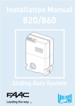
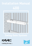
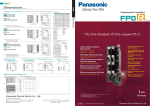
Most Powerful Compact PLC!
This compact PLC offers the processing power and expandability of larger PLCs.
USB & RS232
Programming Port*
Now available in a NEW transistor output model with 4-axis integrated control! The FP-X offers a set of features
and functions that rivals all the competition. With processor speeds of 0.32 usec and 32K of program memory, the FP-X is suitable to
replace both small and expensive high speed PLCs. The FP-X comes with built-in 24v sensor power supply, removable terminal strips
and relay outputs. The FP-X is directly powered by AC input. The expandability is endless. There are communication, analog, discrete I/
O, and motion expansions. The FP-X can also use all the expansions available in the FP0 series PLC.
Key Features
●
Modbus Master and Slave (63 stations)
●
Run-Time Editing
●
50 Micro Second Throughput
●
3 Serial Ports
●
Floating Point Math
●
Expansion Cassettes - Using FP-X Cassettes and FP0 Expansion Units
●
USB and RS232 Programming Port*
●
100 KHz of Motion, 8 High Speed Counters
●
PID with Auto Tuning
●
PLC to PLC Networking - Up to 16 station PLC networks!
*USB available with the AFPX-C30 and C60 CPU only
.
FP-X Models
You may sort models by clicking the arrows in the appropriate column. If you are searching for a particular model but can't find it, give
our model search utility a try. All downloads have moved to our separate downloads center.
Click one of the links below to view all related models. Models will appear below the links.
●
Control Units
●
Digital Cassettes
●
Digital Expansions
●
Communication Cassettes
●
Motion Expansions
●
Communication Expansions
●
Communication/Network
●
Memory Units And Rtc
●
Analog Cassettes
●
Analog Expansions
●
Accessories
●
Manuals And Software
Currently viewing: FP-X Control Units
Model Name
Power
Pulse
Outputs
Modbus Rtu
Dc Inputs
Npn Outputs
Pnp Outputs
Relay
Outputs
Program
Size (K)
Sort
Sort
Sort
Sort
Sort
Sort
Sort
Sort
Sort
AFPX-C14P
AC100-240V
3 Axis
Yes
8
6
12
AFPX-C14PD
24VDC
3 Axis
Yes
8
6
12
AFPX-C14R
AC100-240V
No
Yes
8
6
12
AFPX-C14T
AC100-240V
3 Axis
Yes
8
6
12
AFPX-C14TD
24VDC
3 Axis
Yes
8
6
12
AFPX-C30P
AC100-240V
4 Axis
Yes
16
14
32
AFPX-C30PD
24VDC
4 Axis
Yes
16
14
32
AFPX-C30R
AC100-240V
No
Yes
16
AFPX-C30T
AC100-240V
4 Axis
Yes
16
16
14
32
AFPX-C30TD
24VDC
4 Axis
Yes
16
16
32
AFPX-C60P
AC100-240V
4 Axis
Yes
32
28
32
32
AFPX-C60PD
24VDC
4 Axis
Yes
32
28
32
AFPX-C60R
AC100-240V
No
Yes
32
AFPX-C60T
AC100-240V
4 Axis
Yes
32
28
28
32
32
AFPX-C60TD
24VDC
4 Axis
Yes
32
28
32
■ FP-X Control Unit Dimensions (Unit: mm)
Dimensions when expansion cassettes
(function and communication) are installed
●AFPX-C14 ∗ ∗ (The same dimensions apply to the expansion I/O unit AFPX-E16∗)
COM
Status display LED
N
X5
X3
X0
X2
X4
X7
X6
PROG. ERR.
0
X 4
0
Y 4
Programmable Controller
45
L
RUN
Input/output display LED
Application cassette
Communication cassette
X1
FP-X
60
3
7
3
5
90
Panasonic
RUN
PROG.
Mode selection switch
RUN/PROG.
FP-X C14
min.
max.
V0
V1
45
Analog volume
Tool port connector
0V
Y0
24V
Y2
Y1
C0
C1
C2
Y5
Y3
C3
Y4
13.6
3.5
Application cassette
Communication cassette
Battery
Expansion unit connector
79
8.6
79
●AFPX-C30 ∗ ∗ (The same dimensions apply to the expansion I/O unit AFPX-E30∗ ∗)
100
Mounting dimension diagram
Status display LED
N COM
L
COM
RUN
Input/output display LED
X1
X0
X3
X2
X5
X4
X7
X9
X8
X6
XB
XA
XD
XC
Introducing a New Transistor Output Model
Pulse Output
XF
XE
2-M
4o
r2
PROG. ERR.
0
8
0
Y
8
7
F
7
X
D
-
5
90
FP-X C30
RUN
PROG.
min.
82 ±0.5
Panasonic
Mode selection switch
RUN/PROG.
max.
4-Axis Integrated Control
V0
Analog volume
V1
0V
USB connector
24V
Tool port connector
Y0
C0
Y1
C1
Y2
C2
C3
Y4
Y3
Y5
Y7
Y6
Y9
Y8
YA
C4
YC
YB
YD
Cassette attachment area 1 Cassette attachment area 2
Application cassette
Communication cassette
Battery
FP-X C14
Function cassette
Battery
Expansion unit connector
●AFPX-C60 ∗ ∗
52 ±0.5
92 ±0.5
FP-X C30
ARCT1B273E
DIN hook
Cassette attachment area 1
182 ±0.5
FP-X C60
190
N COM
L
COM
RUN
X
Y
Mode selection switch
RUN/PROG.
X0
PROG.
X3
X2
X5
X4
XA
XF
XD
NC
XE
XC
COM
COM
COM
X11
X10
COM
X13
X15
X14
X12
X19
X17
X16
X18
X1B
X1A
X1D
X1C
X1F
X1E
ERR.
F
1F
D
1D
FP-X C60
V1
V2
max.
V3
0V
Tool port connector
X8
XB
max.
V0
min.
USB connector
X9
Panasonic
min.
24V
X6
7 8
17 18
7 8
17 18
0
10
0
10
RUN
PROG.
Analog volume
X7
Y0
C0
Y1
C1
Y2
C2
C3
Y4
Y3
Y5
Y7
Y6
Y9
Y8
YA
C4
Y10
YC
YB
YD
Cassette attachment area 1
Application cassette
Communication cassette
Battery
C0
Y11
C1
C2
Y12
Y13
C3
Y14
C4
C5
Y15
Y17
Y16
Y1A
Y19
Y18
C6
Y1C
Y1B
Cassette attachment area 2
Application cassette
Battery
Y1D
Expansion connector part
Battery
Expansion unit connector
■ FP-X Expansion FP0 Adapter Dimensions (Unit: mm)
25
60
POWER
I/F
L
ERROR
45
Status
display LED
( 0.5 )
(7)
Panasonic
Expansion connector
90
AFPX-EFP0
FP0-A80
When the expansion
connector is
attached
45
Input/output display LED
X1
90
Status display LED
2-Axis Linear
Interpolation
Simultaneously
in 2 Pairs!
Appearance when mounted
with a C14 control unit
3.5
DIN hook
Power connector 24 V DC
Expansion hook
These materials are printed on ECF pulp.
These materials are printed with earth-friendly vegetable-based (soybean oil) ink.
14-point type
30-point type
FP-X Programmable Controller
ARCT1B273E ’06.8
ARCT1B273E 200608-6YT
http://www.nais-e.com/plc/
Panasonic... the new name for
60-point type
New
Matsushita Electric Works, Ltd.
Related Products
Related Products List
Part Number List
FP Memory Loader
FP0 Expansion Units
Product name
Specifications
Number of I/O points
8
8
Input: 8
Input: 4
Output: 4
8
FP0 E32 Expansion Unit
Input
Output
Connection type
24 V DC Sink/Source (±common)
−
MIL connector
Terminal block
Molex connecter
Terminal block
24 V DC Sink/Source (±common)
Relay output: 2 A
Output: 8
24 V DC
−
8
Output: 8
−
−
16
Input: 16
16
Input: 8
Output: 8
Input: 8
Output: 8
16
32
16
FP0 E16 Expansion Unit
Power supply
voltage
−
24 V DC
FP0 E8 Expansion Unit
FP Web-Server Unit
Product name
−
24 V DC Sink/Source (±common)
Relay output: 2 A
Transistor output:
NPN 0.1 A
−
24 V DC
24 V DC Sink/Source (±common)
Relay output: 2 A
Product number
Part number
FP0-E8X
FP0-E8RS
FP0-E8RM
FP0-E8YRS
AFP03003
AFP03023
AFP03013
AFP03020
FP0-E8YT
AFP03040
MIL connector
Part number
FP Web-Server unit
Data hold type
AFP8671
FP Web Configurator Tool
PCWAY Ver. 2.7 (Operation Data Managing Software)
Product name
AFW10011
PCWAY USB port version
AFW10031
Product name
PCWAY Version upgrade
AFW10401
Key unit IBM printer port version
AFW1031*
Key unit USB port version
AFW1033
* Charged version upgrade for Ver. 2.0 to 2.6.
Control CommX Ver. 1.3 (OCX for Communication)
FP0-E16RS
FP0-E16RM
AFP03323
AFP03313
Product name
Control CommX IBM printer port
AFW20011
Control CommX USB port
AFW20031
MIL connector
FP0-E16T
AFP03343
Output: 16
−
−
MIL connector
FP0-E16YT
AFP03340
Input: 16
Output: 16
−
24 V DC Sink/Source (±common)
Transistor output:
NPN 0.1 A
Transistor output:
NPN 0.1 A
MIL connector
FP0-E32T
AFP03543
Notes: 1) The relay output type expansion units come with a power cable (part number AFP0581). (The transistor output type needs no power cable.)
2) The terminal block type relay output units have 2 terminal blocks (9 pins) made by Phoenix. Use a 2.5 mm wide screwdriver.
Preferably use the specific terminal block screwdriver (part number AFP0806, Phoenix type code SZS 0. 4 × 2.5 mm) or equivalent.
3) The connector-type relay output units have 2 connectors made by Nihon Molex (Molex type code 51067-0900, 9 pins).
Use the specific Molex connector press-fit tool (part number AFP0805, Nihon Molex type code 57189-5000) or equivalent.
4) The transistor output units have a press-fit socket for wire-pressed terminal cable and contacts. Use the press-fit tool (part number AXY52000) for wire-pressed terminal cable.
Key Unit
PCWAY IBM printer port version
AFP03303
Transistor output:
NPN 0.1 A
AFP0610
AFPS30510
Economical type is available for secondary key.
The key unit is available for PCWAY and Control CommX.
Part number
FP0-E16X
24 V DC Sink/Source (±common)
Part number
AFP8670
MIL connector
Terminal block
Molex connecter
−
Product name
Data non-hold type
Part number
*The discontinuation of AFW1031 production is scheduled for August 2007.
Part number
Specifications
FP0 Intelligent Units
Product name
FP0 Thermocouple unit
Specifications
K, J, T, R thermocouple, Resolution: 0.1 °C
K, J, T, R thermocouple, Resolution: 0.1 °C
<Input specifications>
Number of channels:
Input range:
FP0 Analog I/O unit
FP0 A/D Converter Unit
<Output specifications>
Number of channels:
Output range:
<Input specifications>
Number of channels:
Input range:
<Output specifications>
Number of channels:
Output range:
FP0 D/A Converter Unit
Product number
FP0-TC4
FP0-TC8
2 channels
0 to 5 V, –10 to +10 V (Resolution: 1/4000)
0 to 20 mA (Resolution: 1/4000)
1 channel
–10 to +10 V (Resolution: 1/4000)
0 to 20 mA (Resolution: 1/4000)
8 channels
0 to 5, –10 to +10 V, –100 to 100 mV (Resolution: 1/4000)
0 to 20 mA (Resolution: 1/4000)
4 channels
–10 to +10 V (Resolution: 1/4000)
4 to 20 mA (Resolution: 1/4000)
Part number
AFP0420
AFP0421
AFP0480
FP0-A80
AFP0401
FP0-A04V
AFP04121
FP0-A04I
AFP04123
Power supply
Product number
voltage
FP0 CC-Link Slave unit
Specifications
This unit is for making the FP0 function as a slave station of the CC-Link.
Only one unit can be connected to the furthest right edge of the FP0 expansion bus.
Allowed momentary power off time
Ambient temperature
Storage temperature
Ambient humidity
Storage humidity
FP0 I/O Link unit
This is a link unit designed to make the FP0 function as a station to MEWNET-F (remote I/O system).
Part number
Breakdown voltage
Note: Accuracy will change if an FP0 thermocouple unit is used at the same time. For details, please refer to the FP0 catalog
or to the CC-Link Unit manual.
24 V DC
FP0-CCLS
AFP07943
24 V DC
FP0-IOL
AFP0732
Control FPWIN GR for Windows
Product name
Insulation resistance
Type
Part number
English: Full type
English: Small type
English: Ver. up type
Chinese
Chinese: Ver. up type
Korean
CD-ROM for Windows
CD-ROM for Windows
CD-ROM for Windows
CD-ROM for Windows
CD-ROM for Windows
CD-ROM for Windows
*The production of FP1, FP-M, FP3/FP10SH has been discontinued.
FPWIN GR
for Windows
FP-X
FPΣ
FP0
.
FP-e
A
A
A
A
A
A
A
A
A
AFPS10520
AFPS11520
AFPS10520R
AFPS10820
AFPS10820R
AFPS10920
Applicable PLC
FP0
FP1*
FP2
10k
A
A
A
A
A
N/A
A
A
A
FP2SH FP-M*
FP3*
.
FP10SH
A
N/A
A
A
A
N/A
A
A
A
A: Available, N/A: Not available
FPWIN Pro
for Windows
Type
English: Full type
English: Small type
Part number
CD-ROM for Windows
CD-ROM for Windows
AFPS50550
AFPS51550
FP-X
FPΣ
FP0
.
FP-e
A
A
A
A
A
A
Applicable PLC
FP0
FP1*
FP2
10k
A
A
A
A
A
N/A
A
N/A
A
A
Programmable Display GT series
Description
GT01: Main Unit
RS232C type
5 V DC
RS422/RS485 type
STN monochrome LCD
RS232C type
24 V DC
RS422/RS485 type
GT11: Main Unit
RS232C type
24 V DC
RS422/RS485 type
GT21C: Main Unit
RS232C type
STN color LCD
24 V DC
RS422/RS485 type
16
FP3*
.
FP10SH
A
N/A
Control unit
Expansion I/O unit
Black
Ash gry
Black
Ash gry
Black
Ash gry
Black
Ash gry
Black
Ash gry
Black
Ash gry
Black
Silver
Black
Silver
Part number
Current consumption
Weight
AFPX-C14❍❍
26 W or less *2
Approx. 280 g or less
AFPX-C30❍❍
52 W or less *2
Approx. 490 g or less
AFPX-C60❍❍
64 W or less *2
Approx. 780 g or less
AFPX-E16❍❍
8 W or less *2
Approx. 195 g or less
AFPX-E30❍❍
42 W or less *2
Approx. 430 g or less
AFPX-EFP0
0.24 W or less *3
Approx. 65 g
Part number
AFPX-COM1
2 W or less *2
Approx. 20 g
AIGT0030B1
AIGT0030H1
AIGT0032B1
AIGT0032H1
AIGT0030B
AIGT0030H
AIGT0032B
AIGT0032H
AIGT2030B
AIGT2030H
AIGT2032B
AIGT2032H
AIGT2230B
AIGT2230H
AIGT2232B
AIGT2232H
AFPX-COM2
2 W or less *2
Approx. 20 g
AFPX-COM3
2 W or less *2
Approx. 20 g
AFPX-COM4
2 W or less *2
Approx. 20 g
AFPX-COM5
2 W or less *2
Approx. 20 g
AFPX-AD2
2 W or less *2
Approx. 25 g
AFPX-IN8
1 W or less *2
Approx. 25 g
AFPX-TR8
1 W or less *2
Approx. 25 g
AFPX-TR6P
1 W or less *2
Approx. 25 g
AFPX-PLS
2 W or less *2
Approx. 25 g
AFPX-MRTC
2 W or less *2
Approx. 20 g
Expansion FP0 adapter
Product name
1500 V [P-P] pulse width 50 ns, 1 µs (AC power), 500 V [P-P] pulse width 50 ns, 1 µs (DC power) (per noise simulator method) (power terminals)
No corrosive gas and no excessive dust
Conforming to EN61131-2
2
II
*1 Cutoff current 5 mA
Product name
FP2SH FP-M*
A: Available, N/A: Not available
*The production of FP1, FP-M, FP3/FP10SH has been discontinued.
STN monochrome LCD
Vibration resistance
Shock resistance
Noise immunity
Operating condition
EC Directive Compliance Standard
Level of contamination
Over-voltage category
100 to 240 V AC (AC power), 24 V DC (DC power)
85 to 264 V AC (AC power), 20.4 to 28.8 V DC (DC power)
40 A or less (C14), 45 A or less (C30, C60) at 25°C (AC power)
12 A or less at 25°C (DC power)
10 ms or more
0 to +55°C
-40 to +70°C
10 to 95% RH (at 25 °C, non-condensing)
10 to 95% RH (at 25 °C, non-condensing)
Combined input/output terminals - Combined power and ground terminals,
2300 V AC 1 minute (AC power), 500 V AC*1 1 minute (DC power)
Input terminals - Relay output terminals, 2300 V AC*1 1 minute
Input terminals - Transistor output terminals, 500 V AC*1 1 minute
Power terminals - Ground terminals, 1500 V AC*1 1 minute (AC power), 500 V AC*1 1 minute (DC power)
Combined input/output terminals - Combined power and ground terminals, 100 MΩ or higher (500 V DC using an insulation resistance meter)
Input terminals - Output terminals, 100 MΩ or higher (500 V DC using an insulation resistance meter)
Power terminals - Ground terminals, 100 MΩ or higher (500 V DC using an insulation resistance meter)
5 to 9 Hz, single amplitude 3.5 mm/9 to 150 Hz, constant acceleration 9.8 m/s2, 1 sweep/min, 10 sweeps in each XYZ direction
147 m/s2
2. Power Consumption, Weight
Control FPWIN Pro (IEC61131-3 compliant Windows version software)
Product name
Description
Item
Rated voltage
Operating voltage range
Rush current
FP0-A21
FP0 Link Units
Product name
1. General Specifications
FP-X communication cassette
FP-X analog input cassette
FP-X input cassette
FP-X output cassette
FP-X pulse I/O cassette
FP-X master memory cassette
*2 Power consumption by the AC power supply connected to the control unit
*4 Please refer to FP0 users manual for FP0 expansion units.
Please refer to the user manual and specifications for further details.
*3 Power consumption by the DC power supply connected to the expansion FP0 adapter
17
Specifications
Specifications
4. Input Specifications (Control unit, expansion unit)
3. Controls Specifications
Item
Program method
Relay symbol method
Control method
Cyclic operation method
Program memory
Flash ROM built-in (no battery backup required)
Program capacity
16 ksteps (C14), 32 ksteps (C30, C60)
Basic instruction 0.32 µs/step
Operation processing speed
Basic instructions
111
Applied instructions
216
External inputs (X)
1760 points *4
External outputs (Y)
1760 points *4
Internal relay (R)
4096 points
Special internal relay (R)
192 points
2048 points
Link relay (L)
21.6 to 26.4 V DC
Operating voltage range
Approx. 8 mA (Control unit X0 to X3)
Approx. 4.7 mA (Control unit X0 to X7)
Approx. 4.7 mA (Control unit X4 to X7)
Rated input current
Approx 4.3 mA (Control unit X8 and after, expansion unit)
Approx. 4.3 mA (Control unit X8 and after, expansion unit)
8 points/common (C14, E16) 16 points/common (C30, C60)
Input points per common
(Input power polarity either positive or negative)
Min. ON voltage/ON current
19.2 V/3 mA
Max. OFF voltage/OFF current
2.4 V/1 mA
19.2 V/6 mA (Control unit X0 to X3)
19.2 V/3 mA (Control unit X4 and after, expansion unit)
2.4 V/1.3 mA (Control unit X0 to X3)
2.4 V/1 mA (Control unit X4 and after, expansion unit)
Approx. 3 kΩ (Control unit X0 to X3)
Approx. 5.1 kΩ (Control unit X4 to X7)
Approx. 5.6 kΩ (Control unit X8 and after, expansion unit)
Approx. 5.1 kΩ (Control unit X0 to X7)
Approx. 5.6 kΩ (Control unit X8 and after, expansion unit)
Input impedance
Control unit X0 to X7
12285 words (C14), 32765 words (C3R, C60)
256 words
Special data register (DT)
374 words
Response OFF → ON
Index register (I0 to ID)
14 words
time
Master control relay (MCR)
256 points
Number of labels (LOOP)
256 labels
Number of differentiations
Up to program capacity
Number of stepladders
1000 stages
Number of subroutines
500 subroutines
Number of interruption programs
High-speed counter *5
Control unit X8 and after, expansion unit
Built-in (Relay output): single-phase 8 ch (10 kHz x 8 ch)
Built-in (Transistor output): 100 kHz x 2 ch + 20 kHz x 2 ch
Relay output type: Total 14 points (including the high-speed counter)
ON → OFF
0.5 ms to 30 s
Constant scan
Possible
Equipped (usable only when AFPX-MRTC is installed) *7
Item
Description
Rated control capacity (Resistive load)
2 A 250 V AC, 2 A 30 V DC (8 A or less/common)
Output type
1a contact
Output points per common
Response time
Life time
Battery backup
Battery life (when no power is supplied)
Counter 16 points (1008 to 1023), Internal relay 128 points (R2470 to R255F), Data register 55 words
Approx. 8 ms
Mechanical
20 million operations or more (Operation frequency 180 times/min)
Electrical
None
LED display
6. Transistor Output Specifications
Item
Description
Insulation method
Photocoupler
Before installing AFPX-MRTC
C14: 1230 days (actual operation 10 years at 25°C)
C30, C60: 990 days (actual operation 10 years at 25°C)
Output type
After installing AFPX-MRTC
C14: 780 days (actual operation 10 years at 25°C)
Rated loadf voltage
C30, C60: 680 days (actual operation 10 years at 25°C)
Load voltage allowable range
Capable (4 or 8 characters selectable)
Open collector
Capable (328 KB) (backup battery not required)
OFF state leakage current
PLC link function
Max 16 units, link relay 1024 points, link register 128 words (No data transfer or remote programming)
The actual usable number of points is restricted by the hardware.
Specification at the rated input voltage of 24 V DC, 25°C. Frequency may be lower due to the voltage and temperature.
Max frequency may vary by the method of operation. Please refer to the manual for details.
Calendar accuracy at 0°C: 119 sec/month or less, 25°C: 51 sec/month or less, 55°C: 148 sec/month or less (Real-time clock requires a battery.)
When data is stored in the storage area while the battery is not installed, the data is not cleared and the data value may be indefinite.
The same condition occurs when the battery is exhausted.
*9 The number of possible rewrites is 10,000 or less.
NPN type: 4.75 to 26.4 V DC, PNP type: 21.6 to 26.4 V DC
0.5 A
1.5 A
Max. inrush current
Comment storage
Capable
NPN type: 5 to 24 V DC, PNP type: 24 V DC
Max. load current
Output points per common
Rewriting in RUN mode
100,000 operations or more (Operation frequency 20 times/min at the rated control capacity)
Operating indicator
Watch dog timer, program syntax check
Self-diagnosis function
Approx. 10 ms
ON → OFF
Surge absorber
The memory allocated in the storage area by the system register (only when a battery is installed) *8
(More than two batteries can be installed in C30 and C60. In this case, the battery life is extended several times)
Password
4 points/common
OFF → ON
Data register (32765 words)
Backup by F12, P13 commands
Auto-backup at power failure
LED display
5. Relay Output Specifications (Control units, Expansion units)
2 points (0 to 1000) (C14, C30) 4 points (0 to 1000) (C60)
Real-time clock
Same as above
*1 Specification at the rated input voltage of 24 V DC, 25°C.
Transistor output type: Total 8 points (including the high-speed counter)
Periodical interrupt
Potentiometer
Control unit X4 to X7
135 µs or less: Nominal input
50 µs or less: High-speed counter, pulse catch, interruption input setting*1
Control unit X8 and after, expansion unit
0.6 ms or less
Operating indicator
Pulse I/O cassette (AFPX-PLS) for relay output type: One unit (one axis) 100 kHz, or two units (two axes) 80 kHz
Pulse catch input / interrupt input
Control unit X0 to X3
135 µs or less: Nominal input
5 µs or less: High-speed counter, pulse catch, interruption input setting*1
Relay output type: 15 programs (14 external, 1 constant)
Transistor output type: 9 programs (8 external, 1 constant)
Pulse I/O cassette (AFPX-PLS) for relay output type: single-phase 2 ch (80 kHz x 2 ch)
Pulse output *6
0.6 ms or less: Normal input
50 ms or less: High-speed counter, pulse catch, interruption input setting *1
0.6 ms or less
Built-in (Transistor output): single-phase 8 ch (50 kHz x 4 ch + 10 kHz x 4 ch)
18
24 V DC
Rated input voltage
Link data register (LD)
*4
*5
*6
*7
*8
Transistor output
Photo-coupler
Counter capable of counting 1 to 32767
Data register (DT)
Flash ROM
backup *9
Relay output
Insulation method
Total 1024 points: timer capable of counting (1 ms, 10 ms, 100 ms, 1 s) x 32767
Timer/counter (T/C)
Description
Item
Specifications
8 points/common (C14, E16)
ON state voltage drop
Response time
OFF → ON
ON → OFF
Voltage range for external power supply
8 points/common, 6 points/common (C30, C60, E30)
1 µA or less
0.3 V DC or less
1 ms or less*2
1 ms or less*2
21.6 to 26.4 V DC
Surge absorber
Zener diode
Operating indicator
LED display
*2 Please refer to the user manual for Y0 to Y7 of the transistor output type.
19
Specifications
Specifications
4. Input Specifications (Control unit, expansion unit)
3. Controls Specifications
Item
Program method
Relay symbol method
Control method
Cyclic operation method
Program memory
Flash ROM built-in (no battery backup required)
Program capacity
16 ksteps (C14), 32 ksteps (C30, C60)
Basic instruction 0.32 µs/step
Operation processing speed
Basic instructions
111
Applied instructions
216
External inputs (X)
1760 points *4
External outputs (Y)
1760 points *4
Internal relay (R)
4096 points
Special internal relay (R)
192 points
2048 points
Link relay (L)
21.6 to 26.4 V DC
Operating voltage range
Approx. 8 mA (Control unit X0 to X3)
Approx. 4.7 mA (Control unit X0 to X7)
Approx. 4.7 mA (Control unit X4 to X7)
Rated input current
Approx 4.3 mA (Control unit X8 and after, expansion unit)
Approx. 4.3 mA (Control unit X8 and after, expansion unit)
8 points/common (C14, E16) 16 points/common (C30, C60)
Input points per common
(Input power polarity either positive or negative)
Min. ON voltage/ON current
19.2 V/3 mA
Max. OFF voltage/OFF current
2.4 V/1 mA
19.2 V/6 mA (Control unit X0 to X3)
19.2 V/3 mA (Control unit X4 and after, expansion unit)
2.4 V/1.3 mA (Control unit X0 to X3)
2.4 V/1 mA (Control unit X4 and after, expansion unit)
Approx. 3 kΩ (Control unit X0 to X3)
Approx. 5.1 kΩ (Control unit X4 to X7)
Approx. 5.6 kΩ (Control unit X8 and after, expansion unit)
Approx. 5.1 kΩ (Control unit X0 to X7)
Approx. 5.6 kΩ (Control unit X8 and after, expansion unit)
Input impedance
Control unit X0 to X7
12285 words (C14), 32765 words (C3R, C60)
256 words
Special data register (DT)
374 words
Response OFF → ON
Index register (I0 to ID)
14 words
time
Master control relay (MCR)
256 points
Number of labels (LOOP)
256 labels
Number of differentiations
Up to program capacity
Number of stepladders
1000 stages
Number of subroutines
500 subroutines
Number of interruption programs
High-speed counter *5
Control unit X8 and after, expansion unit
Built-in (Relay output): single-phase 8 ch (10 kHz x 8 ch)
Built-in (Transistor output): 100 kHz x 2 ch + 20 kHz x 2 ch
Relay output type: Total 14 points (including the high-speed counter)
ON → OFF
0.5 ms to 30 s
Constant scan
Possible
Equipped (usable only when AFPX-MRTC is installed) *7
Item
Description
Rated control capacity (Resistive load)
2 A 250 V AC, 2 A 30 V DC (8 A or less/common)
Output type
1a contact
Output points per common
Response time
Life time
Battery backup
Battery life (when no power is supplied)
Counter 16 points (1008 to 1023), Internal relay 128 points (R2470 to R255F), Data register 55 words
Approx. 8 ms
Mechanical
20 million operations or more (Operation frequency 180 times/min)
Electrical
None
LED display
6. Transistor Output Specifications
Item
Description
Insulation method
Photocoupler
Before installing AFPX-MRTC
C14: 1230 days (actual operation 10 years at 25°C)
C30, C60: 990 days (actual operation 10 years at 25°C)
Output type
After installing AFPX-MRTC
C14: 780 days (actual operation 10 years at 25°C)
Rated loadf voltage
C30, C60: 680 days (actual operation 10 years at 25°C)
Load voltage allowable range
Capable (4 or 8 characters selectable)
Open collector
Capable (328 KB) (backup battery not required)
OFF state leakage current
PLC link function
Max 16 units, link relay 1024 points, link register 128 words (No data transfer or remote programming)
The actual usable number of points is restricted by the hardware.
Specification at the rated input voltage of 24 V DC, 25°C. Frequency may be lower due to the voltage and temperature.
Max frequency may vary by the method of operation. Please refer to the manual for details.
Calendar accuracy at 0°C: 119 sec/month or less, 25°C: 51 sec/month or less, 55°C: 148 sec/month or less (Real-time clock requires a battery.)
When data is stored in the storage area while the battery is not installed, the data is not cleared and the data value may be indefinite.
The same condition occurs when the battery is exhausted.
*9 The number of possible rewrites is 10,000 or less.
NPN type: 4.75 to 26.4 V DC, PNP type: 21.6 to 26.4 V DC
0.5 A
1.5 A
Max. inrush current
Comment storage
Capable
NPN type: 5 to 24 V DC, PNP type: 24 V DC
Max. load current
Output points per common
Rewriting in RUN mode
100,000 operations or more (Operation frequency 20 times/min at the rated control capacity)
Operating indicator
Watch dog timer, program syntax check
Self-diagnosis function
Approx. 10 ms
ON → OFF
Surge absorber
The memory allocated in the storage area by the system register (only when a battery is installed) *8
(More than two batteries can be installed in C30 and C60. In this case, the battery life is extended several times)
Password
4 points/common
OFF → ON
Data register (32765 words)
Backup by F12, P13 commands
Auto-backup at power failure
LED display
5. Relay Output Specifications (Control units, Expansion units)
2 points (0 to 1000) (C14, C30) 4 points (0 to 1000) (C60)
Real-time clock
Same as above
*1 Specification at the rated input voltage of 24 V DC, 25°C.
Transistor output type: Total 8 points (including the high-speed counter)
Periodical interrupt
Potentiometer
Control unit X4 to X7
135 µs or less: Nominal input
50 µs or less: High-speed counter, pulse catch, interruption input setting*1
Control unit X8 and after, expansion unit
0.6 ms or less
Operating indicator
Pulse I/O cassette (AFPX-PLS) for relay output type: One unit (one axis) 100 kHz, or two units (two axes) 80 kHz
Pulse catch input / interrupt input
Control unit X0 to X3
135 µs or less: Nominal input
5 µs or less: High-speed counter, pulse catch, interruption input setting*1
Relay output type: 15 programs (14 external, 1 constant)
Transistor output type: 9 programs (8 external, 1 constant)
Pulse I/O cassette (AFPX-PLS) for relay output type: single-phase 2 ch (80 kHz x 2 ch)
Pulse output *6
0.6 ms or less: Normal input
50 ms or less: High-speed counter, pulse catch, interruption input setting *1
0.6 ms or less
Built-in (Transistor output): single-phase 8 ch (50 kHz x 4 ch + 10 kHz x 4 ch)
18
24 V DC
Rated input voltage
Link data register (LD)
*4
*5
*6
*7
*8
Transistor output
Photo-coupler
Counter capable of counting 1 to 32767
Data register (DT)
Flash ROM
backup *9
Relay output
Insulation method
Total 1024 points: timer capable of counting (1 ms, 10 ms, 100 ms, 1 s) x 32767
Timer/counter (T/C)
Description
Item
Specifications
8 points/common (C14, E16)
ON state voltage drop
Response time
OFF → ON
ON → OFF
Voltage range for external power supply
8 points/common, 6 points/common (C30, C60, E30)
1 µA or less
0.3 V DC or less
1 ms or less*2
1 ms or less*2
21.6 to 26.4 V DC
Surge absorber
Zener diode
Operating indicator
LED display
*2 Please refer to the user manual for Y0 to Y7 of the transistor output type.
19