1
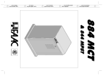
AUTOMATION 820 - 860 & 826 MPS
These instructions apply to the following models:
820 EMC Z20 CR - 820 EMC - 820 EMC RF - 860 MC Z16 - 860
MC - 860 MC RF - 860 EMC Z16 - 860 EMC
The FAAC model 820 and 860 automations for sliding gates
are electromechanical operators which transmit movement
to the leaf by means of a pinion with rack or chain coupled
in an appropriate manner to the sliding gate.
The system is guaranteed to be mechanically locked
when the motor is not in operation so a lock does not need
to be installed. The gear motors have mechanical/
electronic clutches which provide the necessary adjustable
anti-crushing safety. A convenient manual release device
allows the gate to be operated in the event of a power
failure or malfunction. An electronic device allows the
open/closed limit switches to be programmed by a simple
operation without the need to weld limit switch plates. The
electronic control unit is incorporated in the gear motors.
The automations 820 - 860 & 826 MPS have been designed
and built for vehicle access control. Do not use for any
other purpose.
1. DESCRIPTION AND TECHNICAL CHARACTERISTICS
where:
Ta = opening time
Tc = closing time
Tp = pause time
Ti = interval between one complete cycle and the next.
Graph of duty cycle
Percentuale
di lav. %
% Duty cycle
% Fréquence
d'utilisation
% Benutzungsfrequenz
% Frecuencia
de utilización
100
90
80
70
60
50
40
30
20
4
1
10
2
0
3
12
Table 1
5
7
6
11
8
Fig. 1
10
햲
햳
햴
햵
햶
햷
1 2 3 4 5 6 7 8 9 10 11 12
Tempo (h) Time (h) Temps (h)
Zeit (Std.)
Tiempo (h)
Transformer
826 MPS electronic control unit
Surge capacitor
Breather/clutch adjustment screw
Electric motor
ADL electronic card
9 햸 Limit switch unit
햹
햺
햻
햽
햾
Worm screw
Crown wheel
Emergency release
Pinion
Casing
1.1.
MAXIMUM UTILISATION CURVE
The curve allows the maximum working time (T) to be
obtained as a function of duty cycle (F).
For example, the 820-860 gear motors can operate
uninterruptedly at a duty cycle of 30%.
To ensure good operation, keep to the field of operation
lying below the curve.
Important: The curve refers to a temperature of 24°C.
Exposure to direct sunlight can result in a reduction in duty
cycle to as low as 20%.
Calculating duty cycle
The duty cycle is the percentage of effective working time
(opening + closing) with respect to the total cycle time
(opening + closing + pause times).
It is calculated using the following formula:
Ta + Tc
%F =
X 100
Ta + Tc + Tp + Ti
3
Gear motor technical characteristics
MODEL
Power supply
Power consumption (W)
Reduction ratio
No. of pinion teeth
Rack
Max. thrust daN
Winding thermal protection
Duty rating
Oil quantity (l)
Type of oil
Temperature range
Gear motor weight (kg)
Housing protection
Max. gate weight (kg)
Gate speed
Max. gate length
Partial opening length
Cooling
Clutch
Housing treatment
Casing painting
Control unit
Limit switches
Deceleration
Gear motor dimensions LxHxD (mm)
Model
Motor speed (rpm)
Power consumption (W)
Current draw (A)
Surge condenser
Power supply
820
860
230 V (+6% -10%)
400
600
1:30
Z 16 / Z 20
4 module pitch 12.566
50
110
135 °C
30% (see graph)
0,800
FAAC XD 220
-20 to +55°c
14
15
IP 44
600
1200
12 m/min
9,6 m/min
13 m
10 m
1,60 m
1,20 m
self-ventilated
single disc in oil bath
cataphoresis
polyester RAL 7042
826 MPS (incorporated)
programmable memory (ADL)
electronic
see Fig. 3
Electric motor technical specifications
820
860
1400
1400
400
600
2
3
20 µF
30 µF
230 V (+6 -10%) 50 Hz