1
VOICE/FAX/DATA MODEM
USER'S MANUAL
Table of Contents
i - FCC/DOC REQUIREMENTS
i.1 FCC General Information
i.2 FCC Notice
i.3 DOC Notice
1 - INTRODUCTION
2 - COMMAND REFERENCE
2.1 General Command Information
2.2 AT Commands
2.2.a Commands Preceded by &
2.2.b Commands Preceded by \
2.2.c Commands Proceeded by %
2.2.d Commands Preceded by +
2.2.e Commands Preceded by **
2.3 Dial Modifiers
2.4 Commands Not Preceded By AT
2.5 Result Codes
3 - S REGISTER REFERENCE
3.1 Register Summary
3.2 Glossary of the S Registers
4 - TESTING
4.1 Local Analog Loopback
4.2 Local Analog Loopback with Self-Test
5 - TROUBLESHOOTING GUIDE
6 - APPLICATION EXAMPLES
6.1 Dialing a Remote Modem
6.2 Dial a Stored Number
6.3 Manual Answer an Incoming Call
6.4 Auto Answer an Incoming Call
6.5 Voice to Data Switching
A - MNP 10 COMMANDS
B - CALLER ID COMMANDS
C - TECHNICAL SPECIFICATIONS
D - QUICK REFERENCE
E - GLOSSARY
F - ASCII CODE TABLE
i - FCC/DOC REQUIREMENTS
i -1 FCC General Information
The Federal Communications Commission (FCC) of the United States restricts specific uses of modems,
and places registration responsibilities on both the manufacturer and the individual user:
1. The modem may not be connected to a party line or to a coin operated telephone.
2. The modem manufacturer must make any repairs to the modem to maintain valid FCC registration.
3. Notification to the telephone company is no longer required prior to connecting registered
equipment, but upon request from the telephone company, the user shall tell the telephone company
which line the equipment is connected to as well as the registration number and ringer equivalence
number of the registered protective circuitry. FCC information is printed on a label on the bottom of
the modem.
i - 2 FCC Notice
This equipment has been tested and found to comply with the limits for a digital device, pursuant to
Subpart B of Part 15 of the FCC rules. These limits are designed to provide reasonable protection against
harmful interference in a residential installation. This equipment generates and uses radio frequency
energy and if not installed and used the instructions, may cause interference to radio communications.
However, there is no guarantee that interference will not occur in a particular installation. If this
equipment does cause harmful interference to radio or television reception, which can be determined by
turning the equipment off and on, the user is encouraged to try and correct the interference by one or more
of the following measures:
Reorient or relocate the receiving antenna.
Increase the separation between the equipment and receiver.
Connect the equipment into an outlet on a circuit different from that to which the receiver is
connected.
Consult the dealer or an experienced radio/TV technician for help.
Shielded interconnect cables and a shielded power cord must be employed with this equipment to insure
compliance with the pertinent RF emission limits governing this device. Changes or modifications not
expressly approved by the manufacturer could void the user's authority to operate this equipment.
NOTE: The manufacturer is not responsible for any radio or T.V. interference caused by
unauthorized modifications to this equipment. Such modifications could void the
user's authority to operate the equipment.
i - 3 DOC Notice
Notice: The Canadian Department of Communications label identifies certified equipment. This
certification means that the equipment meets certain telecommunications network protective, operational
and safety requirements. The Department does not guarantee the equipment will operate to the user's
satisfaction.
Before installing this equipment, users should ensure that it is permissible to be connected to the facilities
of the local Telecommunications Company. The equipment must also be installed using an acceptable
method of connection. In some cases, the companies inside wiring associated with a single line individual
service may be extended by means of a certified connector assembly (telephone extension cord). The
customer should be aware that compliance with the above conditions might not prevent degradation of
service in some situations.
Repairs to certified equipment should be made by an authorized Canadian maintenance facility designated
by the supplier. Any repairs or alterations made by the user to this equipment, or equipment malfunctions,
may give the telecommunications company cause to request the user to disconnect the equipment.
Users should ensure for their own protection that the electrical ground connections of the power utility,
telephone lines and internal metallic water pipe system, if present, are connected together. This precaution
may be particularly important in rural areas.
Caution: Users should not attempt to make such connections themselves, but should contact the
appropriate electric inspection authority, or electrician, as appropriate.
The Load Number (LN) assigned to each terminal device denotes the percentage or the total load to be
connected to a telephone loop which is used by the device, to prevent overloading. The termination on a
loop may consist of any combination of devices subject only to the requirement that the total of the Load
Numbers of all the devices does not exceed 100.
Note: Locate an analog telephone line. Many offices have digital telephone lines, which will not
work with a modem.
Warning: Do not connect your modem to a digital telephone line. Modems are designed for use
only with analog telephone lines; connecting to a digital telephone line may damage the
modem. Verify that the line is analog before connecting.
Fax machines use analog telephone lines. If you can't find an analog voice line, find a fax machine
and use its line.
1 - INTRODUCTION
Congratulations on your purchase of this outstanding Fax/Data Modem. This manual describes how to
operate your new Fax/Data Modem.
Instructions for installing your Fax/Data Modem will be found in the Installation Manual, while the
information in this manual, deals exclusively with the operation of the modem after it is installed, such as
the command set, the internal configuration registers, troubleshooting and testing.
Features:
These Fax/Data Modems combine the features of a 56000(receive only)/33600/28800/14400/9600 bps data
modem and a 14400/9600 bps FAX modem. Your new Fax/Data Modem gives your personal computer
the ability to send and receive FAX messages over the telephone line like a standard FAX machine. Your
Fax/Data Modem also allows your PC to communicate with other personal computers, terminals or BBS's
(Bulletin Board Systems) through the data modem functions.
When used as a data modem your Fax/Data Modem uses the standard AT command set and is fully
compatible with ITU-T V.42, V.42bis, V.34 (ANNEX 12), V.32bis, V.32, V.22bis, V.23, V.22, V.21,
MNP 2-5, Bell 103, 212A, K56flex and/or V.90. When used as a Fax/Data Modem it communicates with
all ITU-T Group 3 FAX machines and is compatible with ITU-T V.27ter and V.29, V.17, T.4 and T.30.
Switching between DATA mode operation and FAX mode operation of your Fax/Data Modem is done
through its firmware, no hardware settings are required.
If you are already familiar with the use of a modem and the Hayes AT command set, this modem will be
extremely easy for you to use. Just read the installation procedures in the installation manual and you are
ready to begin operation. If you are new to modem communications, we recommend that you read through
this manual first. If you come across terms that you don't understand, consult the glossary. Words in
boldface type are command names, commands, or default settings. Carriage returns (Enter) are noted with
<CR> or [ENTER]; this does not mean to enter these characters literally; but instead to press the Enter
key.
The communication software, which should be used, depends on the kind of machine that you are going to
communicate with. If you are going to call a FAX machine then you must use the Fax software. If the
machine that you are going to communicate with is a modem then you must use a data modem
communications software.
Note: This manual is written to be used for several models of Fax/Data Modems. Some of the
information in this manual may not apply to your fax/data modem.
All the description in this manual about Caller ID, V.90 and Fax class 2 applies only to the models
which support these functions.
2 - COMMAND REFERENCE
This chapter provides an alphabetized reference with examples for all commands for the modem. The
system of commands is depicted below in Figure 2-1.
To use these commands for dialing or configuring the modem, make sure the communications software
package you will be using lets you operate the modem through its internal commands. If your software
permits use of the modem's internal commands, read this chapter. If not, read your software user's manual
and ignore the rest of this manual.
2-1 General Command Information
Except for the A/ command and the +++ escape command described in Section 2.4, all commands must be
prefixed with the attention code AT. For instance, the A command (below) would be entered as: "AT
A<CR>". Without the AT prefix, the command line cannot be executed. Once entered, AT cannot be
deleted with the Backspace or Delete key.
More than one command can be placed on a single line and, if desired, separated with spaces for
readability. Once the carriage return (Enter) key is pressed, the command line is executed. A line with no
carriage return is ignored.
The modem accepts either upper or lower case characters in the command line and ignores any spaces
within or between commands. Typing errors can be corrected with the Backspace key. Exceptions are
noted in the description of specific commands.
Variables (r and x) are listed in Italics. Punctuation symbols (, ; ! @) use as dial modifiers are listed
alphabetically according to their English names at the beginning of Section 2.3. Where two commands are
separated by a slash, either command will have the same effect. For example, if the command is listed as
B0/B, issuing either B0 or B will have the same effect.
2-2 AT Commands
A
Go On-line in Answer Mode
This command instructs the modem to go off-hook immediately and then make a handshake with the
remote modem. Handshaking is not available during leased line operation.
A is usually used to manually answer an incoming call or to switch from voice conversation to data
communication.
Bn
Select Protocol to 300 bps or 1200 bps
B0/B
Selects ITU-T 300 or ITU-T 1200 protocol once the command line prefix AT has been
entered at the 300 bps or 1200 bps data rate.
B1
Selects BELL 300 or BELL 212A protocol once the command line prefix AT has been
entered at the 300 or 1200 bps data rate. (Default)
Cn
Carrier Transmit Control
Controls the transmit carrier. The modem is preset to turn carrier on and off as necessary (the C1 option).
The signal is on when the modem is calling, or connected to a remote modem, and is off when it is not.
The C0 option is NOT valid.
C0
Not permitted; returns ERROR result code.
C1
Normal transmits carrier switching (preset).
D
Go On-line in Originate Mode
D instructs the modem to go off-hook immediately and automatically dial the number contained in the
dial string following D. The dial string may contain any of the dial modifiers contained in the following
section. The D command without a dial string is usually used to switch from voice conversation to data
communication or to call a remote modem in leased-line operation mode.
En
Command Echo
E0/E
Disables command echo.
E1
Enables command echo. (Default)
Hn
Hang Up
H0/H
Goes on-hook. (Hangs up)
H1
Goes off-hook. (ready to dial)
In
Identification
I0/I
Report the product code.
I1
Report the hardware checksum.
I2
Report " ERROR".
I3
Report firmware revision.
I4
Report OEM defined identifier string.
I5
Report the country code parameter.
I6
Report modem data pump model and internal code revision.
I7
Report the DAA code.
Ln
Control Speaker Volume
L0/L
Low volume.
L1
Low volume. (Default)
L2
Medium volume.
L3
High volume.
Mn
Monitor Speaker On/Off
M0/M
Speaker is always off.
M1
Speaker is off while receiving carrier. (Default)
M2
Speaker is always on.
M3
Speaker disabled while dialing or receiving carrier.
Nn
Automode Enable
N0
Automode detection is disabled.
N1
Automode detection is enabled. This command is equivalent to F0. (Default)
On
Return to On-Line Data Mode
O0
Enters on-line data mode without a retrain. Handling is determined by the Call Establishment
task. Generally, if a connection exists, this command connects the DTE back to the remote
modem after an escape (+++).
O1
Enters on-line data mode with a retrain before returning to on-line data mode.
P
Set Pulse Dial as Default
Causes the modem to assume that all subsequent dial commands are pulse dials. You may omit the " P "
from the dial strings.
Q
Result Code Display
Determines whether the modem sends the result codes to the DTE.
Q0
Allows the modem to send result codes to the DTE.
Q1
Sn
Prohibits the modem from sending result codes to the DTE.
Reading and Writing to S Registers
Sn?
Reads S Registers:
Read the contents of the S register specified by 'n'.
Sn=x
Writing to Registers:
Writes the value of x to the specified S register. All the registers will return the OK response
if x is a legal value. However some registers will not actually write the value; these are: S1,
S13-S15, S20-S24, and S27. (n=0-95, x=0-255)
T
Set Tone Dial as Default
Causes the modem to assume that all subsequent dial commands are tone dial.
Vn
Select Word or Digit Result Codes
V0/V
Displays result codes in digital format.
V1
Displays result codes in verbose format. (Default)
Wn
Connect Message Control
This command controls the format of CONNECT messages. The parameter value, if valid, is written to
S31 bits 2 and 3. Note that the Wn command can be overridden by register S95 bits (see S95 description).
W0
Upon connection, the modem reports only the DTE speed (e.g., CONNECT 19200).
Subsequent responses are disabled. (Default)
W1
Upon connection, the modem reports the line speed, the error correction protocol, and the
DTE speed, respectively. Subsequent responses are disabled.
W2
Upon connection, the modem reports the DCE speed (e.g., CONNECT 14400). Subsequent
responses are disabled.
Xn
Extended Result Codes
This command selects which subset of the result messages will be used by the modem to inform the DTE
of the results of commands.
Blind dialing is enabled or disabled by country parameters. If the user wishes to enforce dial tone
detection, a "W" can be placed in the dial string (see D command). Note that the information below is
based upon the default implementation of the X results table.
If the modem is in facsimile mode (+FCLASS=1 or 2), the only message sent to indicate a connection is
CONNECT without a speed indication.
X0
Disables monitoring of busy tones unless forced otherwise by country requirements; send
only OK, CONNECT, RING, NO CARRIER, ERROR, and NO ANSWER result codes.
Blind dialing is enabled/disabled by country parameters. If busy tone detection is enforced
and busy tone is detected, NO CARRIER will be reported. If dial tone detection is enforced
or selected and dial tone is not detected, NO CARRIER will be reported instead of NO DIAL
TONE. The value 000b is written to S22 bits 6, 5, and 4, respectively.
X1
Disables monitoring of busy tones unless forced otherwise by country requirements; send
only OK, CONNECT, RING, NO CARRIER, ERROR, NO ANSWER, and CONNECT
XXXX(XXXX=rate). Blind dialing is enabled/disabled by country parameters. If busy tone
detection is enforced and busy tone is detected, NO CARRIER will be reported instead of
BUSY. If dial tone detection is enforced or selected and dial tone is not elected, NO
CARRIER will be reported instead of NO DIAL TONE. The value 100b is written to S22 bits
6, 5, and 4, respectively.
X2
Disables monitoring of busy tones unless forced otherwise by country requirements; send
only OK, CONNECT, RING, NO CARRIER, ERROR, NO DIAL TONE, NO ANSWER, and
CONNECT XXXX. If busy tone detection is enforced and busy tone is detected, NO
CARRIER will be reported instead of BUSY. If dial tone detection is enforced or selected and
dial tone is not detected, NO DIAL TONE will be reported instead of NO CARRIER. The
value 101b is written to S22 bits 6, 5, and 4, respectively.
X3
Enables monitoring of busy tones; send only OK, CONNECT,
RING, NO CARRIER, ERROR, NO ANSWER, and CONNECT
XXXX. Blind dialing is enabled/disabled by country parameters. If dial tone detection is
enforced and dial tone is not detected, NO CARRIER will be reported. The value 110b is
written to S22 bits 6, 5, and 4, respectively.
X4
Enables monitoring of busy tones; send all messages. The value 111b is written to S22 bits
6, 5, and 4, respectively. (Default)
Yn
Enables or Disables Long Space Disconnect
Y0/Y
Disables Long Space Disconnect. (Default)
Y1
Enables Long Space Disconnect.
Zn
Reset
Zn, which must be placed at the end of the command line, resets the active configuration of the modem to
the stored configuration saved in nonvolatile RAM, hangs up the modem, and clears the command buffer.
Z0/Z
Resets the modem and loads stored configuration 0.
Z1
Resets the modem and loads stored configuration 1.
2.2.a Commands Preceded by &
&Cn
&Dn
Select DCD Options
&C0/&C
Maintains an ON status for the Data Carrier Detect (DCD).
&C1
Uses the actual state of the carrier from the remote modem for DCD. (Default)
DTR Option
Determines actions taken by the modem in relation to the Data Terminal Ready (DTR) signal of the serial
port.
&F
&D0
DTR is ignored. Allows operation with DTEs that do not provide DTR.
&D1
DTR drop is interpreted by the modem as if the escape sequence has been entered. The
modem returns to the command state without disconnecting.
&D2
DTR drop causes the modem to hang up. Auto answer is inhibited. (Default)
&D3
DTR drop causes the modem to perform a soft reset as if the Z command were received.
Fetch Factory Configuration
&F0
Recall factory profile 0. (Default)
&F1
Recall factory profile 1.
&Gn
Set Guard Tone
&G0 - G1
Disable guard tone. (Default)
&G2
Select 1800Hz-guard tone.
&Kn
DTE/Modem Flow Control
Determines how the modem controls the flow of data between the local DTE and the modem. When the
modem terminal buffer is nearly full, the modem will either send an XOFF or drop CTS to stop the data
flow. When the buffer is nearly empty, the modem will either send an XON or raise CTS to start the data
flow.
&K0
Disable DTE/DCE flow control.
&K3
Enable RTS/CTS DTE/DCE flow control. (Default)
&K4
Enables XON/XOFF DTE/DCE flow control.
&K5
Enables transparent XON/XOFF DTE/DCE flow control.
&K6
&Mn
Enable RTS/CTS and XON/XOFF DTE/DCE flow control.
Communication Mode
(Same as &Q0)
&Pn
&Qn
Select Pulse Dialing Make/Break Ratio
&P0/&P
Sets a 39/61 make/break ratio @ 10 pps - used in USA. (Default)
&P1
Sets a 33/67 make/break ratio @ 10 pps.
&P2
Sets a 39/61 make/break ratio @ 20 pps.
&P3
Sets a 33/67 make/break ratio @ 20 pps.
Asynchronous Mode Selection
This command is an extension of the &M command and is used to control the connection modes
permitted. It is used in conjunction with S36 and S48.
&Q0
Select direct asynchronous operation. The value 000b is written to S27 bits 3, 1, and 0
respectively.
&Q5
The modem will try to negotiate an error-corrected link. The modem can be configured using
S36 to determine whether a failure will result in the modem returning on-hook or will result in
fallback to an asynchronous connection. The value 101b is written to S27 bits 3, 1, and 0
respectively. (Default)
&Q6
Select asynchronous operation in normal mode (speed buffering). The value 110b is written
to S27 bits 3, 1, and 0 respectively.
&Sn
DSR Option
Determines whether DSR operates in accordance with the EIA-232-D specification or remains ON
&S0
DSR is always ON. (Default)
&S1
DSR will become active after answer tone has been detected and inactive after the carrier
has been lost.
&Tn
Testing and Diagnostics (See Chapter 4)
Testing commands must be initiated in command mode (at the end of the command line) with
asynchronous operation in the Direct mode, selected (&Q0) at a speed of 1200 bps or faster. A telco
connection must be established prior to loopback tests. If these conditions are not met, an ERROR result
code is issued. If a local analog loopback is initiated while the modem is connected, the modem
disconnects beforeperforming the test. A test remains active for the period of time specified in register
S18. If S18 is zero, the test aborts when the user issues the &T0 command.
&T0/&T
Terminates any test currently in progress.
&T1
Initiates a local analog loopback in accordance with ITU-T V.54, L3; verifies the path
between the local DTE and the local modem.
&T8
&V
View Configuration Profiles
&V
&Wn
&Yn
&Zn
Initiates a local analog loopback with self-test in accordance with ITU-T V.54, L2.
Displays the active configuration profile.
Store the Current Configuration to Nonvolatile RAM
&W0
Writes the current active configuration to profile 0 in nonvolatile RAM.
&W1
Writes the current active configuration to profile 1 in nonvolatile RAM.
Select the Default Profile
&Y0/&Y
Uses profile 0 on power-up. (Default)
&Y1
Uses profile 1 on power-up.
Store Telephone Numbers (n=0to3)
&Zn Store one of four dial strings (including a telephone number) of up to 45 digits in nonvolatile RAM.
For example: to store the telephone number 002852117 to RAM location 1, issue the following command:
Command:AT&Z1=002852117<CR>
2.2.b Commands Preceded by \
\An
Select Maximum MNP Block Size
The modem will operate an MNP error corrected link using a maximum block size controlled by the
parameter supplied.The parameter value, if valid, is written to S40 bits 6 and 7.
\A0
64 characters.
\A1
128 characters. (Default)
\A2
192 characters.
\A3
256 characters.
Result Codes:
\Bn
OK
n=0 to 3.
ERROR
Otherwise.
Transmit Break to Remote
In non-error correction mode, the modem will transmit a break signal to the remote modem with a length
in multiples of 100ms according to parameter specified. If a number in excess of 9 is entered, 9 is used.
The command works in conjunction with the \K command.
In error correction mode, the modem will signal a break through the active error correction protocol,
giving no indication of the length.
\B1-\B9
Break length in 100ms units. (Default=3)
(Non-error corrected mode only.)
Result Codes:
OK
If connected in data modem mode.
NO CARRIER
If not connected or connected in fax modem mode.
Note: When the modem receives a break from the remote modem, break is passed to the DTE as follows:
In non-error correction mode direct, the break length is passed; in non-error correction mode normal and
in error correction mode, a 300 ms break is passed.
\Gn
Modem to Modem Flow Control (XON/XOFF)
Enables or disables modem flow control during a Normal Mode connection. Since
Reliable Mode has its own method of flow control, the \Gn command is ignored when error correction is
selected. However, DTE-to-modem flow control remains active during reliable link.
\Kn
\G0
Disable flow control. (Default)
\G1
Enable flow control.
Break Control
Determines the modem's response when a BREAK is received from the DTE or the remote modem,
according to the following conditions:
When a BREAK is received from the DTE during Normal or MNP Mode:
\K0,2,4
Modem enters Command Mode (waiting for an AT command) without sending a BREAK to
the remote modem.
\K1
Modem clears the terminal and modem buffers.
\K3
Modem does not clear the buffers.
\K5
Modem sends a BREAK to the remote modem in sequence with any transmitted data.
(Default)
When a BREAK is received from the remote modem during Normal Mode:
\K0,1
Modem clears the terminal and modem buffers.
\K2,4
Modem does not clear the buffers.
\K4,5
Modem sends a BREAK in sequence with any transmitted data.
When a BREAK is received from the DTE during Direct Mode:
\K0,2,4
Modem sends a BREAK to the remote modem.
\K1,3,5
Modem sends a BREAK to the remote modem.
\Nn
Operation Mode Control
Selects the operating mode to be used during connection
\N0
Selects Normal (speed buffering) Mode. (Same as &Q6)
\N1
Selects Direct (pass-through) Mode. (Same as &Q0)
\N2
Selects Reliable Link Mode.
\N3
Selects Auto-reliable Mode. Modem attempts to connect with error correction.
\N4
Select LAPM error-correction mode.
\N5
Select MNP error-correction mode.
\Vn
Single Line Connect Message Enable
The single line connect message format can be enabled or disabled by the \Vn command as follows:
\V0
Connect messages are controlled by the command settings X, W, and S95.
\V1
Connect messages are displayed in the single line format described below subject to the
command settings V (Verbose) and Q (Quiet). In Non-Verbose mode (V0), single line
connect messages are disabled and a single numeric result code is generated for
CONNECT DTE.
When single line connect messages are enabled, there are no CARRIER, PROTOCOL, or
COMPRESSION messages apart from the fields described below.
The single line connect message format is:
CONNECT <DTE Speed></Modulation></Protocol></Compression></Line Speed>/<Voice and Data>
Where:
<DTE Speed=
DTE speed, e.g., 57600.
Modulation=
"V32" for V.32 or V.32bis modulations.
"V34" for V.34 modulations.
Note: Modulation is omitted for all other modulations.
Protocol=
"NONE" for no protocol.
"ALT" for Microcom Network Protocol.
"LAPM" for LAP-M protocol.
Compression=
"CLASS5" for Microcom MNP5 compression.
"V42BIS" for V.42bis compression.
Note: Compression is omitted if protocol is NONE.
Line Speed=
Asymmetric rates are displayed as /rate:TX/rate:RX, e.g., /1200 TX/75 RX.
Symmetric rates are displayed as a single DCE rate, e.g., 14400.
Voice and Data=
Blank for Data mode only.
"SVD" for AudioSpan analog simultaneous audio/voice and data.
"DSVD" for G.729A or DigiTalk digital simultaneous voice and data.
2.2.c Commands Preceded by %
%C
Enable/Disable Data Compression
Enables or disable data compression negotiation. The modem can only perform data compression on an
error-corrected link. The parameter value, if valid, is written to S41 bits 0 and 1.
%C0
Disables data compression. Resets S46 bit 1.
%C1
Enables MNP 5 data compression negotiation. Resets S46 bit 1.
%C2
Enables V.42 bis data compression. Sets S46 bit 1.
%C3
Enables both V.42 bis and MNP 5 data compression. Sets S46 bit 1. (Default)
Result Codes:
%En
OK
n=0,1,2,or 3.
ERROR
Otherwise.
Enable/Disable Line Quality Monitor and Auto-Retrain or Fallback/Fall Forward
Control whether or not the modem will automatically monitor the line quality and request a retrain
(%E1) or fall back when quality is insufficient or fall forward when line quality is sufficient (%E2).
Applies to dial-up line only. The parameter value valid is written to S41 bits 2 and 6. If enable, the
modem attempts to retrain for a maximum of 30 seconds.
%E0
Disable line quality monitor and auto-retrain.
%E1
Enable line quality monitor and auto-retrain.
%E2
Enable line quality monitor and fallback/fall forward. (Default)
%E3
Enable line quality monitor and auto-retrain, but hang-up immediately when EQM reaches
hang-up threshold. (fast hang-up)
%L
Report Received Signal Level
Returns a value identifying the received signal level. The possible values are:
%Q
009
-9 dBm.
010
-10 dBm.
011
-11 dBm.
043
-43 dBm.
Line Signal Quality
Reports the line signal quality (DAA dependent). Returns the higher order byte of the EQM value. Based
on the EQM value, retain or fallback/fall forward may be initiated if enabled by %E1 or %E2.
%Un
Select µ_Law or A_Law Codec Type
This command selects µ_Law or A_Law codec type for V.90 and K56 flex modulation similar to the
<x_law> parameter in the +MS command (see +MS command). This command overrides the <x_law>
setting specified in a previous +MS command and the <x_law> parameter in a +MS command overrides a
previous %Un command. This command also stores the selected setting directly to NVRAM.
%U0
%U1
Selects µ_Law.
Selects A_Law.
Result codes:
OK
ERROR
n = 0 or 1.
Otherwise.
2.2.d Commands Preceded by +
+MS
Select Modulation
This extended-format command selects the modulation and, optionally, enables or disables automode,
specifies the lowest and highest connection rates, selects u-Low or A-Low codec type, and enables or
disables robbed bit signaling generation (server modem) or detection (client modem) using one to five
subparameters. The command format is:
+MS=<mod>
[,[<automode>][,[<min_rate>][,[<max_rate>][,[<x_law>][,[<rb_signaling>]]]]]]<CR>
Notes:
1. For 14400 bps and lower speeds, the Nn command and S37 register can alternatively be used, in
which case the +MS subparameters will modified to reflect the Nn and S37=x settings. Use of the
Nn and S37=x commands is not recommended but is provided for compatibility with existing
communication software. (S37 is not updated by the +MS command.)
2. Subparameters not entered (enter a comma only or <CR> to skip the last subparameter) remain at
their current values.
Reporting Selected Options
The modem can send a string of onformation to the DTE consisting of selected options using the
following command:
+MS?
The response is:
+MS:
<mod>,<automode>,<min_rate>,<max_rate>,<x_law>,<rb_signaling>
For example,
K56flex:
+MS:
56,1,300,56000,0,0
V.90:
+MS:
12,1,300,56000,0,0,33600 (RC56 default values)
Reporting Supported Options
The modem can send a string of information to the DTE consisting of supported options using the
following command:
+MS=?
The response is:
+MS:
(list of supported <mod> values), (list of supported <automode> values), (list of supported
<min_rate> values), (list of supported <max_rate> values), (list of supported <x_law> values), (list of
supported <rb_signaling> values)
For example,
+MS:
(0,1,2,3,9,10,11,12,56,64,69), (0,1), (300-33600), (300-56000), (0,1), (0,1)
Subparameter Definitions
1. <mod>= A decimal number which specifies the preferred modulation (automode enabled) or
modulation (automode enabled) to use in originating or answering a connection. The options are:
<mod>
0
1
2
3
9
10
11
12
Modulation
V.21
V.22
V.22 bis
V.23
V.32
V.32 bis
V.34
Possible Rates (bps)1
300
1200
2400 or 1200
1200
9600 or 4800
14400, 12000, 9600, 7200 or 4800
33600, 31200, 28800,
26400, 24000, 21600, 19200, 16800,
14400, 12000, 9600, 7200, 4800, or
Notes
See Note 2
2400
V.90
56000, 54677, 53333, 52000, 50669,
49333, 48000, 46667, 45333, 42667,
41333, 40000, 38667, 37333, 36000,
34667, 33333, 32000, 30667, 29333,
28000
56 K56flex
56000, 54000, 52000, 50000, 48000,
46000, 44000, 42000, 40000, 38000,
36000, 34000, 32000
64 Bell 103
300
69 Bell 212
1200
Notes: 1. See optional <automode>, <min_rate>, and <max_rate> subparameters.
2. For V.23, originating modes transmit at 75 bps and receive at 1200 bps; answering modes transmit at 1200
bps and receive at 75 bps. The rate is always specified as 1200 bps.
The modem may also automatically switch to another modulation (automode), subject to the following
constraints:
a. The modem may not be able to automatically switch from the current modulation (specified by
<mod>) to some other modulation. For example there is no standard way to automode from Bell
103 to V.23.
b. The DTE may disable automode operation (see <automode> below).
c. The DTE may constrain the range of modulations available by specifying the lowest and highest
rates (see <min_rate> and <max_rate> below).
2. <automode> is an optional numeric value, which enables or disables automatic modulation
negotiation using V.8 bis/V.8 or V.32 bis Annex A. The options are:
<automode>
0
1
Option Selected
Automode disabled
Automode enabled using V.8 bis/V.8 or V.32
Annex A
Notes
default
The default value is 1, which enablesautomode. Note, however, there are modulations for which
there is no automode negotiation, e.g., Bell 212 (<mod>=69).
For <automode> = 0 (automode disabled, i.e., fixed modulation):
a. If <max_rate> is within the rates supported by the selected modulation, the selected rated is that
specified by <max_rate>. For example,
+MS=10, 0, 1200, 4800 selects V.32 bis 4800 bps fixed rate.
b. If <max_rate> is greater than the highest speed supported by the modulation specified by
<mod>, the starting rate is the highest rate supported by the selected modulation. For example,
+MS=10, 0, 2400, 14400 selects V.32 bis 14400, 12000, 9600, 7200, or 4800 bps.
c. To emulate issuance of the N0S37=x command sequence to select fixed mode operation, specify
the <max_rate>and<min_rate> both to be the (same) requested speed, and <mod> to be the
modulation for that speed. For example,
+MS=11, 0, 16800, 16800 selects V.34 16800 bps fixed mode (no comparable S37 command).
+MS=10, 0, 12000, 12000 selects V.32 bis 12000 bps fixed mode (same as N0S37=10).
For <automode> = 1 (automode enabled, i.e., automatically selected speed and modulation):
The modem connects at the highest possible rate in accordance with V.8 bis/V.8, or V.32 bis
Annex A if V.8 bis/V.8 is not supported by the remote modem.
a. If <max_rate> is greater than the highest rate supported by the modulation specified by <mod>,
the modem automodes down from the highest rate of the selected modulation. For example,
+MS=10, 1, 1200, 24000 selects automoding down from V.32 bis 14400 bps.
b. To emulate issuance of the N1S37=x sequence command, specify the modulation and the rate to
start automoding down from using <mod> and <max_rate>, respectively. Set <min_rate> to
300 to allow automoding all the way to V.21 300 bps. For example:
+MS=11, 1, 300, 16800 selects automodestarting at V.34 16800 bps (no comparable S37 command).
+MS=9, 1, 300, 12000 selects automode starting at V.32 bis 12000 bps same as N1S37=10).
3. <min_rate> is an optional number specifies the lowest rate at which the modem may establish a
connection. The value is decimal coded, in units of bps, e.g., 2400 specifies the lowest rate to be
2400 bps. The default is 300 for 300 bps.
4. <max_rate> is an optional number specifies the highest rate at which the modem may establish
a connection. The value is decimal coded, in units of bps, e.g., 14400 specifies the highest rate
to be 14400 bps. The default is 28800 for 28800 bps.
5. <x_law> is an optional number, which specifies the codec type. The options are:
0=µ-Law
1=A-Law
Note that ATZ will reset the <x_law> selection to 0 (µ-law).
* Also note that the <x_law> parameter in a +MS command overrides a previous %Un
command and a %Un command overrides the <x_law> setting specified in a previous +MS
command.
6. <rb_signaling> is an optional number, which enables or disables robbed bit signaling
generation in a server modem or enables or disables robbed bit signaling detection in a client
modem. The options are:
0=Robbed bit signaling generation (server modem) or detection (client modem) disabled. (Default)
1=Robbed bit signaling generation (server modem) or detection (client modem) enabled.
Note that ATZ will reset the <rb_signaling> selection to 0. (Default)
Result Codes:
OK
ERROR
Valid subparameter string
Otherwise.
2.2.e Commands Preceded by **
**
Download to Flash Memory
The linear flash memory downloader in the modem firmware allows flash memory connected to the
modem external memory bus to be upgraded with revised modem firmware. This process transfers
(uploads) the upgraded modem firmware (data) from the host computer to the modem which transfers
(downloads) the data to the flash memory device. Note that this command apply only to the modem with
flash memory.
Programming the flash memory device is a two-step process.
1. When the AT** command is issued, the modem firmware boot loader is invoked and the user will first
load a flash load module (FLM) into the modem's RAM. The FLM contains the programming
algorithm for the flash memory device being programmed and any messages that may be sent during
the load process.
2. The user will then load the new modem firmware, which the FLM will then program into the flash
memory device.
Procedure:
1. Install in the modem a flash memory programmed with the modem firmware; ensure that the flash
memory device is programmed with the sector secure mode set to UNSECURE (AMD only), otherwise
the device connot be re-programmed in the modem.
2. Put the FLM file and the new modem firmware file (e.g., V1400DS.S37) in an appropriate directory
on the computer's hard disk.
3. Configure the communications application program for a DTE rate of between 9600 bps and 57600
bps (57600 bps is faster) and RTS/CTS flow control. A load at 57600 bps will take approximately 2
minutes; a load at 19200 bps will take approximately 6 minutes.
4. Check the modem for response by typing AT.
5. Initiate the download process using the AT**n command, where:
AT**/AT**0
AT**1
AT**2
download speed is the last sensed speed (recommended command).
Download speed is 38.4k bps.
Download speed is 57.6k bps.
The "Download initiated" message appears upon issuing the AT**n command.
6. Perform an ASCII upload of the FLM file (e.g., AMDE.S37) from the host computer to the modem
RAM using an industry standard communications software of an equivalent process (ensure that all
ASII transmit or pacing is turned off).
To abort the load at this point, wait for the FLM download process to time-out, send a bad S37 record,
or reset (POR) the modem. If the load process times-out, the modem must be reset (ATZ) before the
FLM can be loaded again.
7. After the FLM has been loaded, perform an ASCII upload of the new modem firmwarehex file (e.g.,
RC288ACi.S37) from the host computer to the modem RAM using industry standard communications
software or an equivalent process. There will be a 3-second pause after the first record of the
RC288AXX.S37 file is sent, which is the FLASH erase cycle. There is no turning back at this point.
If the flash download fails (because of a bad .S37 record for example) or the upload is aborted, as long
as the modem is not turned off or reset, it will remain in the flash load cycle and the upload can be reattempted at step 7.
A "Wrong Device" message is displayed if an incorrect FLM is used. In this case, restart at step 5 and
upload the correct FLM file.
A "Wrong Hex file or flow control" message is displayed if an incompatible hex file format is used
(non-Motorola S3 format) or if the DTE ignores flow controls (the flash download uses both Xon/Xoff
and RCS/CTS flow control). If the wrong format was used, reinitiate the upload at step 7 using a
correct firmware hex file.
8. A "Device successfully programmed" message is displayed by the FLM at the completion of a
successful download and the modem will do a cold start.
2.3 Dial Modifiers
This section describes all of the dial modifiers, which are used in dial strings.
@
Answer
"@", placed after a phone number, this modifier tells the modem to wait for 5 seconds of silence before
dialing the next number in the dial string. @ is usually used to access a secure computer system that
provides a silent answer as permission for further entrance.
,
Pause
",", placed anywhere in the dial string, tells the modem to pause for the number of seconds specified by Sregister S8 before processing the rest of the dial string.
!
Initiate a Hookflash
"!", placed anywhere in the dial string, tells the modem to initiate a hookflash, which means to hang up
for 0.5 seconds and then go off-hook again before processing the rest of the dial string. This modifier
allows access to PBX features like call transferring.
;
Return to Command State after Dialing
";", which must be placed at the end of the dial string, returns to the command state after dialing the
number placed ahead of it. A long telephone number would overflow the 40-character command buffer if
placed all in one command line, so it must be broken into two or more command lines. Each part includes
part of the number, and all but the last command line end with the ";" followed by a carriage return.
^
Tone Control
Toggles calling tone enable/disable: applicable to current dial attempt only.
J
Perform MNP
Perform MNP 10 link negotiation at 1200 bps (for this call only).
K
Enable Power Level
Enable power level adjustment during MNP 10 link negotiation
L
(for this call only).
Re-dial Last Number
The modem will re-dial the last valid telephone number. The L must be immediately after the D with all
the following characters ignored.
P
Pulse Dialing
P, placed ahead of a number, tells the modem to dial a number using pulse dialing.
S
Dial a Stored Number
S is used to dial one of four numbers stored in nonvolatile memory. For example, instead of entering a dial
string, you can use this command:
Command: ATDTS=1<CR>
T
Touchtone Dialing
T, placed ahead of a number, tells the modem to dial a number using touchtone dialing.
W
Wait for Dialtone
W, placed after a number, tells the modem to wait up to 30 seconds to detect a one-second continuous
dialtone before dialing the next number. W is most often used in a PBX system to wait for the dialtone of
an outside telephone line.
2.4 Commands Not Preceded by AT
Two commands, A/ and +++, are neither preceded by the attention code AT nor followed by a carriage
return.
A/
Repeat Command
A/ repeats the execution of the last command line stored in the command buffer. If the last command line
is invalid, the ERROR result code will appear on the screen. Note that A/ cannot be preceded by AT; if it
is, ERROR will appear on the screen.
+++
Escape
+++ followed by AT <CR> allows the modem to escape from the data mode to the on-line command state
(command state without breaking the established connection.)
To escape, stop transmitting data, wait at least one escape guard time (the default time is one second), and
then enter three consecutive escape characters (the default character is +) followed by AT <CR>.
The modem will return to the command state and send the OK result code to the screen. Note that the
escape command is the only command that can be recognized by the modem in the one-line state; it
cannot be recognized in the command state.
2.5 Result Codes
The modem sends a response to the user via the screen after a command is issued. As shown in the figure
below, there are two forms for each result code: Modem Response code and digit code.
Modem Response
OK
CONNECT
RING
NO CARRIER
Digit
0
1
2
3
Description
Command executed without errors
Connect to another modem
Detect an incoming ring
Carrier lost or never detected
ERROR
4
Invalid command or invalid character
CONNECT 1200
5
Connection established at 1200 bps
NO DIALTONE
6
Dial tone not detected within timeout
BUSY
7
Detected a busy tone after dialing
NO ANSWER
8
No ringback or quiet answer was detected by the modem
CONNECT 600
9
Connection established at 600 bps
CONNECT 2400
10
Connection established at 2400 bps
CONNECT 4800
11
Connection established at 4800 bps
CONNECT 9600
12
Connection established at 9600 bps
CONNECT 7200
13
Connection established at 7200 bps
CONNECT 12000
14
Connection established at 12000 bps
CONNECT 14400
15
Connection established at 14400 bps
CONNECT 19200
16
Connection established at 19200 bps
CONNECT 38400
17
Connection established at 38400 bps
CONNECT 57600
18
Connection established at 57600 bps
CONNECT 115200
19
Connection established at 115200 bps
CONNECT 230400
20
Connection established at 230400 bps
CONNECT 1200RX/75TX
22
V.23 connection established:transmit at 75 bps, receive at 1200 bps
CONNECT 75RX/1200TX
23
V.23 connection:transmit at 1200 bps, receive at 75 bps
DELAYED
24
Call fails to connect and number dialed is considered 'delayed' due to
country blacklisting requirements
BLACKLISTED
32
Call fails to connect and the number dialed is considered 'blacklisted'
FAX
33
A fax modem connection is established in a facsimile mode
DATA
35
A data modem connection is established in a facsimile mode
CARRIER 300
40
Carrier detected
CARRIER 1200TX/75RX V.23 44
Carrier detected
CARRIER 75RX/1200TX V.23 45
Carrier detected
CARRIER 1200
46
Carrier detected
CARRIER 2400
47
Carrier detected
CARRIER 4800
48
When the 4800 bps data rate in V.32 bis or V.32 mode has been
detected on the line
CARRIER 7200
49
When the 7200 bps data rate in V.32 bis mode has been detected
on the line
CARRIER 9600
50
When the 9600 bps data rate in V.32 bis or V.32 mode has been
detected on the line
CARRIER 12000
51
When the 12000 bps data rate in V.32 bis mode has been detected on the
line
CARRIER 14400
52
When the 14400 bps data rate in V.32 bis mode has been detected on the
line
CARRIER 16800
53
When the 16800 bps data rate in V.34 mode has been detected on the line
CARRIER 19200
54
When the 19200 bps data rate in V.34 mode has been detected on the line
CARRIER 21600
55
When the 21600 bps data rate in V.34 mode has been detected on the line
CARRIER 24000
56
When the 24000 bps data rate in V.34 mode has been detected on the line
CARRIER 26400
57
When the 26400 bps data rate in V.34 mode has been detected on the line
CARRIER 28800
58
When the 28800 bps data rate in V.34 mode has been detected on the line
CONNECT 16800
59
Connection established at 16800 bps
CONNECT 21600
61
Connection established at 21600 bps
CONNECT 24000
62
Connection established at 24000 bps
CONNECT 26400
63
Connection established at 26400 bps
CONNECT 28800
64
Connection established at 28800 bps
COMPRESSION CLASS 5
66
MNP class 5 compression in use
COMPRESSION V.42BIS
67
V.42 bis compression in use
COMPRESSION NONE
69
No compression is being used
PROTOCOL:NONE
76
Normal mode selected
PROTOCOL:LAPM
77
LAPM mode selected
CARRIER 31200
78
When the 31200 bps data rate in V.34 mode has been detected on the line
CARRIER 33600
79
When the 33600 bps data rate in V.34 mode has been detected on the line
PROTOCOL:ALT
80
PROTOCOL:ALT-CELLULAR 81
CONNECT 33600
84
Connection established at 33600 bps
CONNECT 31200
91
Connection established at 31200 bps
CARRIER 32000
150
Connection established at 32000 bps
CARRIER 34000
151
Connection established at 34000 bps
CARRIER 36000
152
Connection established at 36000 bps
CARRIER 38000
153
Connection established at 38000 bps
CARRIER 40000
154
Connection established at 40000 bps
CARRIER 42000
155
Connection established at 42000 bps
CARRIER 44000
156
Connection established at 44000 bps
CARRIER 46000
157
Connection established at 46000 bps
CARRIER 48000
CARRIER 50000
CARRIER 52000
CARRIER 54000
CARRIER 56000
CONNECT 32000
CONNECT 34000
CONNECT 36000
CONNECT 38000
CONNECT 40000
CONNECT 42000
CONNECT 44000
CONNECT 46000
CONNECT 48000
CONNECT 50000
CONNECT 52000
CONNECT 54000
CONNECT 56000
+FCERROR
158
159
160
161
162
165
166
167
168
169
170
171
172
173
174
175
176
177
+F4
** V.90 Result Codes
Speed
28000
29333
30667
32000
33333
34667
36000
37333
38667
40000
41333
42337
45333
46667
48000
49333
50667
52000
53333
54667
56000
Carrier
180
181
182
150
183
184
152
185
186
154
187
188
189
190
158
191
192
160
193
194
162
Connection established at 48000 bps
Connection established at 50000 bps
Connection established at 52000 bps
Connection established at 54000 bps
Connection established at 56000 bps
Connection established at 32000 bps
Connection established at 34000 bps
Connection established at 36000 bps
Connection established at 38000 bps
Connection established at 40000 bps
Connection established at 42000 bps
Connection established at 44000 bps
Connection established at 46000 bps
Connection established at 48000 bps
Connection established at 50000 bps
Connection established at 52000 bps
Connection established at 54000 bps
Connection established at 56000 bps
Connect
180
181
182
165
183
184
167
185
186
169
187
171
189
190
173
191
192
175
193
194
177
3 - S REGISTERS REFERENCE
Your modem has status registers. These registers are memory locations inside your modem which control
your modem's operation. You usually do not have to worry about setting any register because the default
values work for most applications.
The S registers are summarized in Fig. 3-1, along with their default values. Registers denoted with an " *
" may be stored in one of the two user profiles by entering the &Wn command. One of these profiles may
be loaded at any time by using the Zn command.
The factory default values are stored in ROM and are loaded into the active configuration at power-up or
by the Zn command. In addition, the designated default profile is subsequently loaded, and may change
some of the factory default values. The designated default profile can be changed by entering the &Yn
command, where 'n' is one of the two possible user profiles. The factory defaults can be loaded at any time
by entering the &F command.
3.1 Register Summary
The following chart summarizes your modem's registers:
Reg.# Range
Unit
S0
0 - 255
rings
S1
0 - 255
rings
S2
0 - 255
ASCII
S3
0 - 127
ASCII
S4
0 - 127
ASCII
S5
0 - 255
ASCII
S6
2 - 255
seconds 2
S7
1 - 255
seconds 50*
S8
0 - 255
seconds 2*
S9
1 - 255
1/10 sec.
S10 1 - 255
1/10 sec.
S11 50 - 255
1/1000 sec.
S12 0 - 255
1/50 sec.
S14 [Bit Mapped Options]* 138
S18 0 - 255
seconds
S21 [Bit Mapped Options]
4*
S22 [Bit Mapped Options]
S23 [Bit Mapped Options]
54
S24 0 - 255
seconds
S25 0 - 255
seconds
S26 0 - 255
1/100 sec
S28 [Bit Mapped Options]
0*
S29 0 - 255
10 ms
S30 0 - 255
10 s
S31 [Bit Mapped Options]
194*
S32 0 - 255
ASCII
S33 0 - 255
ASCII
S36
S37
S38 0 - 255
seconds
S39
S40 [Bit Mapped Options]
S41
S46
S48
S82
S86 0 - 255
S91 0 - 15
dBm
10
S92 0 - 15
dBm
S95
[Bit mapped]
0*
Dec
0
0
43
13
10
8
02h
32h
02h
6*
14*
95
50*
8Ah
0*
04h
117*
36h
0
5*
1*
00h
70*
0*
C2h
7*
0*
20*
3
104
3
138*
7*
128*
0Ah
10
00h
Default
Hex
Description
00h
Number of rings before auto-answer.
00h
Ring count.
2Bh
Escape character code.
0Dh
Command terminator (<CR>character).
0Ah
Line feed character.
08h
Backspace character.
Wait time for blind dialing.
Wait time for carrier after dial.
Pause time for comma (dial delay).
06h
Carrier detect response time.
0Eh
Lost carrier to hang-up delay.
5Fh
DTMF Tone Duration.
32h
Escape code timing.
00h
Test mode timer.
V.24/General bit-mapped options.
75h
Speaker/Results Bit-mapped options.
00h
05h
01h
Sleep Inactivity Timer.
Dalay to DTR.
RTS to CTS Delay Interval.
46h
00h
Flash Dial Modifier Time.
Inactivity Disconnect Timer.
17
19
07h
00h
14h
03h
68h
03h
8Ah
07h
80h
11h
XON Character.
13h
XOFF Character.
LAPM Failure Control.
Desired Line Connection Speed.
Delay before Forced-Disconnect.
Flow Control.
General Bit Mapped Options.
Bit-Mapped Options.
Protocol Selection.
V.42 Negotiation Action.
Break Handling Option.
Call Failure Reason Code.
PSTN Transmit Attenuation Level.
0Ah
Fax Transmit Attenuation Level.
Extended result codes.
Fig. 3-1 S-Register Summary
3.2 Glossary of S Registers
S0
Number of Rings Before Auto Answer
S0 determines the number of rings that must be received before the modem automatically answers an
incoming call. For example, when S0=3, the modem automatically answers after the third ring. When
S0=0, the modem does not automatically answer an incoming call; it stays on-hook until the A command
is issued manually to answer the incoming call.
Range:
S1
Ring Count
0 - 255 rings
S1 automatically increments its value by one each time the modem receives a ring while in the command
state. S1 is reset to zero if no ring is detected within 8 seconds.
Range:
S2
0 - 255 rings
ASCII Value of Escape Character
S2 stores the ASCII value of the escape character. Setting register S2 to a value greater than 127 disables
the escape command and you cannot return to the command state. With escape disabled, in the on-line
state the modem cannot hang up until the power is turned off or the remote modem hangs up.
Range:
S3
0 - 255, ASCII decimal.
ASCII Value of Carriage Return
S3 stores the ASCII value of the carriage return character. (Pertains to asynchronous operation only.)
Range:
S4
0 - 127, ASCII decimal.
ASCII Value of Line Feed Character
S4 stores the ASCII value of the line feed character, if your computer does not recognize the default as a
line feed, change the value. A value greater than 127 disables the line feed. When disabled, the line feed
character that precedes or follows a result code is canceled.(Pertains to asynchronous operation only.)
Range:
S5
0 - 127, ASCII decimal.
ASCII Value of Backspace Character
S5 stores the ASCII value of the backspace character. The backspace is used to edit a command line. If
your computer does not recognize the default as a backspace, change the value. (Pertains to asynchronous
operation only.)
Set S5 to any value from 0 to 31 or 127. Do not set it to any value from 32 through 126 because these
values correspond to printable ASCII characters. A value greater than 127 disable the backspace and
makes it impossible to edit a command line.
Range:
S6
0 - 32, ASCII decimal.
Wait Time before Blind Dialing
S6 controls how long the modem waits after it goes off-hook before it dials the first digit of the telephone
number. The modem always pauses for at least 2 seconds, even if S6 is set to less than two seconds.
Range:
2 - 255 seconds.
S7
Wait for Carrier after Dial
S7 controls how long the modem waits for a carrier signal from a remote modem after originating a call
or from the calling modem after going off-hook when answering a call.
S7 also controls how long the modem waits for a one-second continuous dialtone after dialing a number
followed by the W dial modifier. If the modem detects a one-second continuous dialtone within the
specified wait time, it proceeds to dial.
Range:
S8
1 - 255 seconds.
Pause Time for Comma
S8 controls how long the modem pauses when a comma ", " is encountered in a dial string while
executing a dial command.
Range:
S9
0 - 255 seconds.
Carrier Detect Response Time
S9 determines how long a carrier signal must be present for the modem to confirm it. The longer the
response time, the easier it is for the modem to correctly recognize a carrier without mistaking other
signals or transient noise on the line as a carrier.
Range:
S10
1 - 255 tenths of a second.
Delay between Loss of Carrier and Hang-Up
S10 determines the delay time between the loss of a carrier from the remote modem and hang-up. This
allows for a temporary loss of carrier without causing the local modem to disconnect. When S10 is set to
255, the modem functions as if a carrier is always present.
The actual interval the modem waits before disconnecting is the value in S10 minus the value in S9.
Therefore, the value in S10 must be greater than that in S9, or else the modem disconnects before it
recognizes the carrier.
Range:
S11
1 - 255 tenths of a second.
DTMF (Touch-tone) Tone Duration
S11 determines the duration and spacing of tones for Dual Tone Multifrequency (DTMF) dialing. This
value has no effect on pulse dialing.
Range:
S12
50 - 255 milliseconds.
Escape Guard Time
S12 determines the escape guard time. The escape guard time is the minimum waiting time required
before and after entering the escape code (three consecutive escape characters) in the on-line state. It is
also the maximum waiting time allowed between any two consecutive escape characters. If the waiting
time before or after the escape code is shorter than the guard time, or if the waiting time between
consecutive escape characters is longer than the guard time, then the modem does not recognize the
escape command and stays on-line.
If the escape guard time is set at 0 second, it is impossible to return the modem to command state.
Range:
S14
Bit Mapped Options
Bit
bit 1 (E)
bit 2 (Q)
bit 3 (V)
bit 4
bit 5 (P or T)
bit 6
bit 7
S18
0 - 255 1/50 of a second.
Value
Description
0
Disabled.
1
Enabled.
0
Disabled.
1
Enabled.
0
Numeric.
1
Verbose.
Reserved
0
T (Tone dial).
1
P (Pulse dial).
Reserved
0
Answer mode.
1
Originate mode.
Test Timer
The test timer determines how long tests are performed. The modem automatically ends the test when the
test time is expired. The default value of 000 disables the test timer. When the timer is thus disabled, all
tests must be ended with the &T0 command.
Range:
S21
V.24/General Bit Mapped Options
Bit
bit 0
bit 2
bit 3,4
bit 5
bit 6
bit 7
S22
0 - 255 seconds.
Value
0
1
0
1
00
01
10
11
0
1
0
1
0
1
Description
&J0.
&J1.
&R0.
&R1.
&D0.
&D1.
&D2.
&D3.
&C0.
&C1.
&S0.
&S1.
Y0.
Y1.
SPEAKER/Results Bit Mapped Options
Bit
bit 0,1
Value
00
01
10
11
Description
Select L0.
Select L1.
Select L2.
Select L3.
bit 2,3
bit 4,5,6
bit 7
S23
00
Select M0.
01
Select M1.
10
Select M2.
11
Select M3.
000
Select X0.
001
Reserved.
010
Reserved.
011
Reserved.
100
Select X1.
101
Select X2.
110
Select X3.
111
Select X4
[RESERVED]
Bit Mapped Options
Bit
bit 0
Value
0
1
000
001
010
011
100
101
110
111
00
01
10
11
00
01
10
bit 1,2,3
bit 4,5
bit 6,7
S24
Description
&T5.
&T4. (default)
Communications rate = 300 bps.
Communications rate = 600 bps.
Communications rate = 1200 bps.
Communications rate = 2400 bps.
Communications rate = 4800 bps.
Communications rate = 9600 bps.
Communications rate = 19200 bps.
Communications rate = 38400 bps or higher.
Even parity selected.
Not used.
Odd.
None.
&G0.
&G1.
1800Hz. (&G2)
Sleep Inactivity Timer
Set the length of time, in units of 10 seconds, that the modem will operate in normal mode with no
detected telephone line of DTE line activity before entering low-power sleep mode.
Range:
S25
0 - 255 (seconds)
Delay to DTR
S25 serves two purposes. When the modem is operating in synchronous mode 1, the value assigned to S25
specifies the length of time the modem waits after a connection has been made before examining DTR.
This allows the modem to ignore an ON-to-OFF transition of DTR, giving the user time to disconnect the
modem from the asynchronous terminal and attach it to a synchronous terminal, without forcing the
modem back to the asynchronous command mode. During this time, the value for S25 is read in whole
seconds.
In all other modes, and after call establishment in synchronous modes 1 and 4, the value is read in 1/100
seconds. In any mode, a change in DTR (ON or OFF) that persists for a period shorter than the value held
in S25 is ignored by the modem while it is in data mode.
Range:
0 - 255 (1 second for synchronous mode 1;
0.01 second otherwise)
S26
RTS to CTS Delay Interval
Pertains to synchronous operation only. When CTS tracks RTS (&R0) and the modem detects an ON-toOFF transition on RTS, this register sets the time delay before the modem turns CTS to ON.
Range:
S28
Bit Mapped Option Status
bit 0, 1
bit 2
bit 3, 4
Reserved.
Reserved.
Pulse dialing (&Pn).
0 = 39%-61% make/break ratio at 10 pulse per second (&P0).
1 = 33%-67% make/break ratio at 10 pulse per second (&P1).
2 = 39%-61% make/break ratio at 20 pulse per second (&P2).
3 = 33%-67% make/break ratio at 20 pulse per second (&P3).
Reserved.
MNP Link Negotiation Speed (*Hn).
0 = Link negotiation at highest speed (*H0).
1 = Link negotiation at highest speed (*H1).
2 = Link negotiation at highest speed (*H2).
bit 5
bit 6-7
S29
Flash Dial Modifier Time
Range:
S30
0 - 255 hundredths of a second
0 - 255 10ms intervals
Inactivity Disconnect Timer
This register determines the length of time, in seconds, the modem waits before disconnecting when no
data is sent or received. This only operates in &Q5 and &Q6 modes, a value of 0 in this register disables
the timer.
Range:
S31
Bit Mapped Options
Bit
bit 1
Value
0
1
bit 2, 3
00
01
10
S32
Description
Controls auto line speed detection (Nn).
Disable (N0).
Enable (N1).
Controls error correction progress messages (Wn).
DTE speed only (W0).
Full reporting (W1).
DCE speed only (W2).
XON Character
Range:
S33
0 - 255 tenths of a second
0 - 255, ASCII decimal
XOFF Character
Range:
0 - 255, ASCII decimal
S36
LAPM Failure Control
This register is read when the S48 register contains the value 128 or if an attempted
error-correction link fails. These fallback options are initiated immediately upon
connection if S48 = 128
Bit
bit 0,1,2
001
established.
011
100
101
110
S37
010
Reserved.
Modem stays on-line and a Normal mode connection is
established.
An MNP connection is attempted and if it fails, the modem
disconnects.
An MNP connection is attempted and if it fails, a direct
mode connection is established.
Reserved.
111
An MNP connection is attempted and if it fails, the normal
mode connection is established.
Desired Line Connection Speed
bit 0-4
bit 5-7
S38
Value
Action
000
Modem disconnect.
Modem stays on-line and Direct mode connections
Desired line connection speed. This is interlinked with
the Fn command. If an invalid number is entered, the number
is accepted into the register, but S37 will act as if the
default value has been entered.
0 = Attempt auto mode connection.
1-3 = Attempt to connect at 300 bps.
4 = Reserved.
5 = Attempt to connect at V.22 1200 bps.
6 = Attempt to connect at V.22bis 2400 bps.
7 = Attempt to connect at V.23.
8 = Attempt to connect at V.32 bis/V.32 4800 bps.
9 = Attempt to connect at V.32 bis/V.32 9600 bps.
10 = Attempt to connect at V.32 bis 12000 bps.
11 = Attempt to connect at V.32 bis 14400 bps.
12 = Attempt to connect at V.32 bis 7200 bps.
Reserved.
Delay Before Forced-Disconnect
This register controls how long the modem waits, after receiving the ATH command or loss of DTR,
before it disconnects from the telephone line. When connected in an error-corrected mode, you can use
this register to ensure that all data is transmitted from the modem's buffer before the modem disconnects.
If you set S38 between 0 and 254, the modem waits that number of seconds for the remote modem to
acknowledge all data before it disconnects. If you set S38 to 255, the modem waits indefinitely for the
remote modem to acknowledge all data.
Range:
S39
0 - 255 seconds
Flow Control
Bit
bit 0-2
Value
000
011
100
Connect speed
No flow control.
RTS/CTS &K3.
XON/XOFF &K4.
bit 3-7
S40
101
Transparent XON &K5.
110
Both Method &K6.
Reserved.
General Bit Mapped Options
Bit
bit 0-1
Value
0
1
2
bit 2
0
1
bit 3-5
0
1
2
3
4
5
bit 6-7
0
1
2
3
S41
Bit-Mapped Options
Bit
bit 0,1
Value
00
01
10
11
bit 6,2
00
01
10
bit 3
0
1
bit 4
0
1
bit 5
bit 7
0
1
S46
Description
MNP Extended Services (-Kn).
Disable extended services (-K0).
(Default for non MNP 10 models).
Enable extended services (-K1).
(Default for MNP 10 models).
Enable extended services (-K2).
Power level Adjustment for Cellular Use ( )Mn).
Auto - adjustment ( )M0).
Force adjustment ( )M1).
Break handling (\Kn).
\K0.
\K1.
\K2.
\K3.
\K4.
\K5.
MNP block size (\An).
64 chars (\A0).
128 chars (\A1).
192 chars (\A2).
256 chars (\A3).
Description
Compress selection %Cn.
Disable %C0.
MNP 5 %C1.
V.42 bis %C2.
MNP 5 and V.42 bis (%C3)
Auto retrain %En.
Retrain disable %E0.
Retrain enable %E1.
Fallback/fall forward enable (%E2).
Modem-to-modem flow control \G.
Disable \G.
Enable \G1.
Block mode control \Ln.
Store mode \L0.
Block mode \L1.
Reserved.
Enable fallback to V.22bis/V.22 (-Qn).
Disable (-Q0).
Enable (-Q1).
Protocol Selection
This register controls whether the modem tries to use data compression when the modem establishes an
error corrected link. The default is for the modem to use data compression (138).
Value
136
138
Description
Execute error correction protocol with no compression.
Execute error correction protocol with compression.
S48
V.42 Negotiation Action
Value
0
7
128
S82
Description
Disable negotiation: bypass the detection and negotiation phases.
Enable negotiation.
Disable negotiation: bypass the detection and negotiation phases.
Break Handling Option
S82 is for compatibility purposes only, changing this register will not any affect.
S86
Call Failure Reason Code
When the modem issues a NO CARRIER result code, a value is written to this S-Register to help
determine the reason for the failed connection. S86 records the first event that contributes to a NO
CARRIER message. The cause codes are:
Range:
S86 =
S86 =
S86 =
at the other end.
S86 =
S86 =
S86 =
the same message.
S86 =
S91
0, 4, 5, 9, 12, 13, or 14
0
4
5
Normal disconnect, no error occurred.
Loss of carrier.
V.42 negotiation failed to detect an error-correction modem
9
12
13
The modems could not find a common protocol.
Normal disconnect initiated by the remote modem.
Remote modem does not respond after 10 retransmission of
14
Protocol violation.
PSTN Transmit Attenuation Level
Sets the transmit attenuation level from 0 to 15 dBm for the PSTN mode resulting in a transmit level from
0 to -15 dBm.
Range:
S92
0 to 15 dBm (Corresponding to 0 to -15 dBm transmit level).
Fax Transmit Attenuation Level
Sets the transmit attenuation level from 0 to 15 dBm for the fax mode resulting in a transmit level from 0
to -15 dBm.
Range:
S95
0 to 15 dBm (Corresponding to 0 to -15 dBm transmit level).
Extended Result Codes
This register can override some of the W command options. Set the appropriate bit to 1 to enable the
corresponding result code, regardless of the W command setting Set the bit to 0 to disable the result code.
Bit
0
1
2
3
4
5
6
7
Description
CONNECT indicates DCE speed.
Append /ARQ to the CONNECT result code if the protocol is other than NONE.
CARRIER result code.
PROTOCOL: result code.
Reserved.
COMPRESSION: result code.
Reserved.
Reserved.
4 - TESTING
The modem provides five testing features to identify fault location when transmission quality is not good:
local digital loopback, local analog loop back, local analog loopback with self-test, remote digital
loopback, and remote digital loopback with self-test. These tests are initiated with the &Tn command
described in Chapter 2.
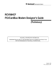
4.1 Local Analog Loopback
The local analog loopback test checks the integrity of the local computer or terminal and the local modem.
During the test, the local modem internally loops data sent from the local computer or terminal back to
the same computer or terminal as shown in Figure 4-1. During the test, data is not transmitted to the
remote modem.
If characters are looped correctly during this test, both the modem and the local computer or terminal are
functioning correctly. If incorrect characters appear on the screen, either the local computer or terminal or
the local modem is in error.
To perform a local analog loopback, put the local modem in the command state. If it is on-line, issue the
escape command + + +, to return to the command state.
Example 1 - test timer disabled
Command:
AT&Q0<CR>
ATS18=0&TI <CR>
Result:
CONNECT 56000
Test message:
THE QUICK BROWN FOX JUMPS OVER THE
LAZY DOG 1234567890
Escape:
+++
(return to the on-line command state)
Result code:
OK
Command:
AT&T0 <CR> (end the test)
Result code:
OK
Here, the test timer is disabled and the modem sets up an internal analog loop as shown in Figure 4-1.
When the loopback is established, the modem goes on-line and the test message (any character you type)
is looped back on the screen for verification. Finally, +++ returns the modem to the command state and
&T0 ends the test and breaks the internal analog loop.
The following command sequence is the same as the previous one except that the test timer is set to 60
seconds. At the end of the test time, the timer expires, the test ends, and the test result is reported.
Example 2 - test timer enabled
Command:
AT&Q0<CR>
ATS18=60&T1<CR>
Result:
CONNECT 56000
Test message:
THE QUICK BROWN FOX JUMPS OVER
THE LAZY DOG 1234567890
Escape:
+++
Result code:
OK
4.2 Local Analog Loopback with Self-Test
The local analog loopback with self-test checks the integrity of the local modem. In this test, an internally
generated data pattern of alternate binary ones and zeros (reversals) at the selected bit rate is looped
through the internal analog loop inside the local modem to an internal error counter as shown in Figure 42. An error count of 255 indicates that 255 or more errors were detected.
Example-the test timer is disabled and 12 errors are found during the test
Command:
AT&Q0<CR>
ATS18=0&T8<CR>
Result:
OK
Command:
AT&T0<CR> (ends the test)
Test result:
000
Result code:
OK
5 - THROUBLESHOOTING GUIDE
This chapter describes common problems in the installation, configuration and regular usage of your
Fax/Data Modem. To test the Fax/Data Modem, a communication software package is needed and the
package must include a mode that allows you to operate your Fax/Data Modem by directly issuing internal
commands to the modem.
Follow the procedures in the following sections to resolve these common problems:
No Response From Your Modem
1. If you are using the internal add-on card modems, make sure that the COM port address you have
set your modem to corresponds to the appropriate selection in the communications software which
you are using.
2. Issue the ATZ command to reset your modem. The returned result code should be "0" or "OK"
depending on what communications program you are using. Your modem is OK if you get one of
these responses. If there is no response after issuing the ATZ<CR>, continue to the next step.
3. Check if there are any other interface cards in your computer that use the same COM port
address as your modem. If so, you must set your modem to another COM port address. (Keep in
mind that on most systems, only two COM ports are available. One of them must be used as either
1 or 3, while the other must be used as 2 or 4.) For example, if a mouse is set to COM 1, your
modem should be set to COM2 or COM4. Continue to the next step if the COM port address is
OK.
4. Issue the command: AT&F&W <CR>, if a "0" or "OK" result code is displayed on the screen,
your modem is OK. Otherwise, contact your dealer for assistance.
Your Modem Does Not Dial Out
Make sure that your modem responds normally as described in section 4.1. If you can communicate
through the keyboard, check whether the modem is properly connected to the phone line.
Your Modem Does Not Connect After It Has Dialed a Phone Number
The problem may have several causes. The phone line may be too noisy or the telephone cord may be
poor. Try the line with a regular phone. Also the remote modem may not recognize your modem's baud
rate.
Your Can't Transmit After You Have Connected to the Remote Modem
In this case, check the communication parameters of the remote modem, then configure your software to
the same number of data bits, stop bit, and parity.
6 - APPLICATION EXAMPLES
6.1 Dialing a Remote Modem
Command line: ATDP9WT002, (886)-7128423<CR>
This command line instruct the modem to dial a remote modem through a PBX. The modem first use
pulse dialing to dial 9 (the access code of the PBX), wait for outside dial tone, and then use touch tone
dialing to dial 002 once a one-second continuous dial tone is detected within 30 seconds, pause for 2
seconds (if S8=2) and then dial 8867128423.
6.2 Dialing a Stored Number
Command line: AT&Z2=T03,709394<CR>
Command line: ATDS=2<CR>
The first command line store the dial string T03, 709394 to the 3rd location in NVRAM. Afterwards you
can use the second command line to dial this stored number. The dial string T03, 709394 will appear on
the screen to indicate the number being dialed.
6.3 Manual Answer an Incoming Call
Command line: ATA <CR>
The factory setting of the S-register S0 is S0=0. This condition disables the auto answer capability so that
you must issue an ATA command to answer a call. At power up, your modem always monitors if there are
incoming rings. If incoming rings are detected, your modem will display result codes on the screen as :
RING
:
:
RING
Seeing that, you may issue the ATA command to answer the call. This command must be entered within
the quiet interval between any two rings.
6.4 Auto Answer an Incoming Call
Command line: AT S0=2 &W &Y <CR>
Auto answer can be enabled by changing the setting of the S-register S0 to a value between 1 and 255. In
the above command line, S0=2 instructs the modem to answer an incoming call automatically after the
2nd ring. The &W command writes this configuration to profile 0 in NVRAM. &Y command instruct the
modem to load profile 0 as the active configuration on power-up. The last two commands make S0=2 the
default value at power-up or reset.
This example also shows the insertion of space between two neighboring commands to make the
command line more readable.
6.5 Voice to Data Switch
Command line: ATA <CR> or ATX1D <CR>
If you are talking with a remote modem user through the telephone set and want to initiate data
communication with the remote modem, follow the procedures below:
1. You or the remote user issue an ATA command first to switch to data communication.
2. When the person on the other end hears an answer tone from the phone, issues an ATX1D
command (X1 to disable the dial tone monitor) to instruct the modem to go off-hook and wait for a
carrier. If connection is successful, the CONNECT XXXX result code will be displayed on the
screen. Now you can hang up your phone and begin data communication with the remote modem.
A - MNP 10 COMMANDS
A-1
MNP 10 COMMANDS
AT) Commands
)Mn
Enable Cellular Power Level Adjustment
Enables or disables automatic adjustment of the transmit power level during link negotiation for reliable
links to accommodate the signaling requirements of cellular telephone equipment. The parameter value, if
valid, is written to S40 bit 2. Note that the @Mn command sets the initial transmit level.
)M0
Disables power level adjustment during MNP 10 link negotiation. (default)
)M1
Enables power level adjustment during MNP 10 link negotiation.
Result Codes:
OK
n = 0 or 1.
ERROROtherwise.
AT-Commands
*Hn
Link Negotiation Speed
This command controls the connection speed for link negotiations before upshift occurs between two MNP
Class 10 modems. The parameter value, if valid, is written to S28 bits 6 and 7.
*H0
Link negotiation occurs at the highest supported speed. (default)
*H1
Link negotiation occurs at 1200 bps.
*H2
Link negotiation occurs at 4800 bps.
Result Codes:
OK
n = 0 to 2.
ERROR Otherwise.
-Kn
MNP Extended Services
Enables or disables conversion of a V.42 LAPM connection to an MNP 10 connection. The parameter
value, if valid, is written to S40 bit 0, 1.
-K0
Disables V.42 LAPM to MNP 10 conversion.
-K1
Enables V.42 LAPM to MNP 10 conversion. (default)
-K2
Enables V.42 LAPM to MNP 10 conversion; inhibits MNP Extended Services initiation during
V.42 LAPM answer mode detection phase.
Result Codes:
OK
n = 0 or 1.
ERROR Otherwise.
-Qn
Enable Fallback to V.22 bis/V.22
Enables or disables fallback from MNP 10 to V.22 bis/V.22. The parameter value, if valid, is written to
S41 bit 7.
-Q0
Disables fallback to 2400 bps (V.22bis) and 1200 bps (V.22). Fallback is enabled only to 4800 bps.
-Q1
Enables fallback to 2400 bps (V.22bis) and 1200 bps (V.22). (default)
Result Codes:
OK
n = 0 or 1.
ERROR Otherwise.
B - CALLER ID COMMANDS
#CIDn - Caller ID (Enables or disables Caller ID.)(for U.S.A)
This command only apply to models which support the Caller ID function.
#CID=0
Disables Caller ID.(Default.)
#CID=1
Enables Caller ID with formatted presentation to the DTE. The modem will present the data items
in a <Tag><Value> pair format. The expected pairs are data, time, caller code (telephone
number), and name.
#CID=2
Enables Caller ID with unformatted presentation to the DTE. The modem will present the entire
packet of information, excluding the leading U's, in ASCII printable hex numbers.
Result Codes:
OK
n=0 or 2.
ERROR Otherwise.
Inquiries :
#CID?
Retrieves the current Caller ID mode from the modem.
#CID=?
Returns the mode capabilities of the modem in a list with each element separated by commas.
Formatted Form Reporting
The modem presents the data in the <tag>=<value> pair format as described in the table below.Spaces are
present on both sides of the equal sign.
TAG
DATE
number (01..31).
Description
DATE=MMDD where MM is the month number(01 to 12) and DD is the day
TIME
TIME=HHMM where HH is the hour number (00 to 23) and MM is the minute
number (00 to 59).
NMBR
NMBR=<number> or P or O where <number> is the telephone number of the
caller, where P indicates that the calling number information is not available
since the
originating caller has requested private service, and where O
indicates that the calling number
information is not available or out of service
at the calling location.
NAME
NAME=<listing name> where <listing name> is the subscription name.
MESG
MESG=<data tag><length of message><data><checksum> in printable ASII
hex numbers. This tag indicates a data item not listed above. The message is
only
possible for Multiple Message Format.
Notes:
1. The modem does not present any Caller ID information if the DCE detects a checksum error in
the Caller ID packet.
2. In the event of an unrecognized data tag, the modem will present the data in ASCII hex
numbers following the MESG tag.
Example of Formatted Form Reporting
1. The following example illustrates the standard Caller ID message packet.
RING
DATE = 0321
TIME = 1405
NMBR = 504551234
NAME = A N OTHER
RING
RING
2. The following example illustrates the case where the tag of the packet is not recognized by the
modem.
RING
MESG = 06034242431
RING
RING
Unformatted Form Reporting
The modem presents all information and packet control information found in the message. The modem,
however, excludes the leading U's (channel seizure information) from the presentation. The packet is
presented in ASCII printable hex numbers, the modem does not insert spaces, or line feeds, for formatting
between bytes or words of the packet. The modem does not detect the checksum of the packet.
Example of Unformatted From Reporting
RING
0412303332323234303539313435353132333435
RING
RING
C - TECHNICAL SPECIFICATIONS
C.1 Features
Data Rates(bps)
K56flex:
300, 1200, 2400, 4800, 7200, 9600, 12000, 14400, 19200, 21600, 24000, 26400, 28800,
31200, 32000, 33600, 34000, 36000, 38000, 40000, 42000, 44000, 46000, 48000, 50000,
52000, 54000, 56000
V.90:
56000, 54667, 53333, 52000, 50667, 49333, 48000, 46667, 45333, 42667, 41333, 40000,
38667, 37333, 36000, 34667, 33333, 32000, 30667, 29333, 28000 (Receive only)
Compatibility
(Data)
(Fax)
ITU-T V.90 (for modem which supports V.90 only), V.34, V.32 bis, V.32,
V.22 bis, V.23, V.22, and V.21
Bell: 212A and 103, K56flex
ITU-T V.17, V.29, V.27 ter, and V.21 ch 2
Command Set Enhanced 'AT' command set, Fax Class 1command
Flow Control Xon/Xoff, Hardware RTS/CTS
Data Compression
V.42bis, MNP5
Error Correction
V.42, MNP 2-4
Operation
Full-or Half-duplex 28800 bps with 26400, 24000, 21600, 19200, 14400, 9600,
4800, 2400 and 1200 bps auto fallback
Test Modes
Analog loopback, local digital loopback, and remote digital loopback
Audio Monitor
Built-in speaker, with software-controllable volume control
Guard Tone
550/1800 Hz
Compliance
FCC 15&68
Command Buffer
40 characters
Extra Memory
4 x 36 digits
Transmit Level
-11(+/-1)dBm
Receive Sensitivity -40dBm
Pulse Dialing Specifications
Compatibility:
B - QUICK REFERENCE
A
Go On-line in Answer Mode
Bn
Select Protocol to 300 bps or 1200 bps
Cn
Carrier Transmit Control
D
Go On-line in Originate Mode
En
Command Echo
Hn
Hang Up
In
Identification
Ln
Control Speaker Volume
Mn
Monitor Speaker On/Off
Nn
Automode Enable
On
Return to On-line Data Mode
P
Set Pulse Dial as Default
Q
Result Code Display
Sn
Reading and Writing to S Registers
T
Set Tone Dial as Default
Vn
Select Word or Digit Result Codes
Wn
Negotiation Progress Reporting
Xn
Extended Result Codes
Yn
Enables or Disables Long Space Disconnect
Zn
Reset
&Cn
Select DCD Options
&Dn
DTR Option
&F
Fetch Factory Configuration
&Gn
Set Guard Tone
&Kn
DTE/Modem Flow Control
&Mn
Communication Mode
&Pn
Select Pulse Dialing Make/Break Ratio
&Qn
Asynchronous Mode Selection
&Sn
DSR Option
&Tn
Testing and Diagnostics (See Chapter 4)
&V
View Configuration Profiles
&Wn
Store the Current Configuration to Nonvolatile RAM
&Yn
Select the Default Profile
&Zn
Store Telephone Numbers (n=0 to 3)
\An
Select Maximum MNP Block Size
\Bn
Transmit Break to Remote
\Gn
Modem to Modem Flow Control (XON/XOFF)
\Kn
Break Control
\Nn
Operating Mode Control
\Vn
Single Line Connect Message Enable
%Cn
Enable/Disable Data Compression
%En
Enable/Disable Line Quality Monitor and Auto-Retrain or Fallback/Fall Forward
%L
Report Received Signal Level
%Q
Line Signal Quality
+MS
Select Modulation
**
Download to Flash Memory(For models with flash Memory only)
@
Answer
,
Pause
!
Initiate a Hookflash
;
Return to Command State after Dialing
^
Tone Control
J
Perform MNP
K
Enable Power Level
L
Re-dial Last Number
P
Pulse Dialing
S
Dial a Stored Number
T
Touchtone Dialing
W
Wait for Dialtone
A/
Repeat Command
+++
Escape
E - GLOSSARY
ASCII - An acronym for American Standard Code for Information Exchange. ASCII is a seven-bit code
which defines 128 standard characters, including control characters, letters, numbers, and symbols. An
extra 128 characters comprise the extended ASCII set.
Baud Rate - The transmission rate between two serial devices, e.g., modems, fax machines, etc.
Measured in Bits Per Second.
Blind Dialing - In blind dialing, the modem continues to dial, regardless of the existence of a dialtone,
ring, or busy signal.
BPS - Bits Per Second; the number of bits that can be transmitted in one second.
Carrier Signal - The analog data signal that a modem sends over telephphone wires.
COMx - Where (x = 1, 2, 3, or 4), COMx is the name(address) of serial communications ports on
personal computers. Each serial port in a personal computer has a different number.
CTS - Clear To Send.
Default - The assumed value that is used for a command parameter when no other value is explicitly
provided.
DCD - Data Carrier Detect.
DCE - Data Communication Equipment.
DTE - Data Terminal Equipment.
DTMF - Dual Tone Multifrequency(for touchtone dialing).
DTR - Data Terminal Ready.
FSK - Frequency Shift Keying.
Make/Break Ratio - The ratio of the off-hook (make) to on-hook (break) interval is the make/break ratio
in pulse dialing.
Modem - A combination of the words MOdulator and DEModulator. Modems transform digital data
into analog signals and back again.
Nonvolatile Memory - An area of memory inside the modem where the default configuration profile is
stored. Values recorded in this memory will not be lost when the power is turned off.
Off-Hook - The condition when the modem has picked up the telephone line.
Off-Line Command State - A modem state in which the modem accepts, interprets and executes
commands from an asynchronous computer or terminal.
On-Hook - The condition when the modem has not picked up the telephone line; the telephone is hung
up.
On-Line - A carrier signal link with a remote modem has been established; communication is in
progress.
On-Line State - A modem state in which the modem is connected with a remote modem. Data can be
sent or received from the remote modem in this state. No commands will be accepted from the modem
except the escape command which will bring the modem into the on-line command state.
On-Line Command State - A modem state in which the modem can accept or execute commands
from an asynchronous computer or terminal while remaining connected with the remote modem. The user
can return the modem to the on-line state by issuing the AT0n command or put it into the off-line
command state by issuing command such as ATZ or ATH.
Parity - An error-checking method by which the modem verifies that the data just sent is correct.
pps - Pulse per second.
Profile - A list of default settings.
Protocol - A technical specification for serial communications; the protocols supported by the modem
are listed in Appendix B.
PSK - Phase Shift Keying.
Pulse Dialing - A dialing form in which each digit is represented by a series of pulses. Rotary telephones
all use pulse dialing.
QAM - Quadrature Amplitude Modulation.
Result Codes - The response the modem returns to the screen upon executing a command.
RAM - Random Access Memory.
ROM - Read-Only Memory. A chip inside the modem which stores the factory default settings. This
memory cannot be changed.
RTS - Request To Send.
RX - Reception.
S Register - RAM locations in the modem which store the active configuration.
Serial Port - See COMx.
TCM - Trellis-Coded Modulation.
Touchtone Dialing - A dialing format in which each digit is represented by a musical frequency.
TX - Transmission.
F - ASCII CODE TABLE
Decimal Hex Value
000
00 NUL
001
01 SOH
002
02 STX
003
03 ETX
004
04 EOT
005
05 ENQ
006
06 ACK
007
07 BEL
008
08 BS
009
09 HT
010
0A LF
011
0B VT
012
0C FF
013
0D CR
014
0E SO
015
0F SI
016
10 DLE
017
11 DC1
018
12 DC2
019
13 DC3
020
14 DC4
021
15 NAK
022
16 SYN
023
17 ETB
024
18 CAN
025
19 EM
026
1A SUB
027
1B ESC
028
1C FS
029
1D GS
030
1E RS
031
1F US
Decimal Hex Value Decimal Hex Value
032
20 (space)064
40 @
033
21 !
065
41 A
034
22 "
066
42 B
035
23 #
067
43 C
036
24 $
068
44 D
037
25 %
069
45 E
038
26 &
070
46 F
039
27 '
071
47 G
040
28 (
072
48 H
041
29 )
073
49 I
042
2A *
074
4A J
043
2B +
075
4B K
044
2C ,
076
4C L
045
2D 077
4D M
046
2E .
078
4E N
047
2F /
079
4F O
048
30 0
080
50 P
049
31 1
081
51 Q
050
32 2
082
52 R
051
33 3
083
53 S
052
34 4
084
54 T
053
35 5
085
55 U
054
36 6
086
56 V
055
37 7
087
57 W
056
38 8
088
58 X
057
39 9
089
59 Y
058
3A :
090
5A Z
059
3B ;
091
5B [
060
3C <
092
5C \
061
3D =
093
5D ]
062
3E >
094
5E ^
063
3F ?
095
5F _
Decimal Hex Value
096
60 '
097
61 a
098
62 b
099
63 c
100
64 d
101
65 e
102
66 f
103
67 g
104
68 h
105
69 i
106
6A j
107
6B k
108
6C l
109
6D m
110
6E n
111
6F o
112
70 p
113
71 q
114
72 r
115
73 s
116
74 t
117
75 u
118
76 v
119
77 w
120
78 x
121
79 y
122
7A z
123
7B {
124
7C |
125
7D }
126
7E ~
127
7F DEL