1
GB
INSTALLATION MANUAL
®
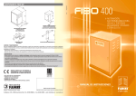
FIBO
300
INSTRUCTIONS FOR THE INSTALLATION OF THE SLIDING
GATE OPERATOR
FOR CORRECT FIBO 300 INSTALLATION AND GOOD PERFORMANCE, PLEASE READ THE INSTRUCTIONS OUTLINED IN THIS MANUAL
CAREFULLY AND KEEP TO THE DIAGRAMS.
IMPORTANT: THE ENTIRE INSTALLATION MUST BE CARRIED OUT BY QUALIFIED TECHNICAL PERSONNEL IN COMPLIANCE WITH
EN 12453 – EN 12445 SAFETY STANDARDS AND IN ACCORDANCE WITH MACHINERY DIRECTIVE 98/37/EC.
GENERAL INFORMATION
The three-phase 1.1KW (1.5 HP) FIBO 300 is an automation for heavy sliding gates and industrial doors (the field of use varies from a
gate weight of 1˙000 to approx. 2˙500 Kg); the gear motor unit is installed inside a sheet steel protection cover, which is fixed to a thick
metal base plate. The protection cover houses the power panel and the electronic command programmer, while the limit switches are
already attached to the body of the gear motor. The protection cover can only be accessed by using the customized key. This is a strong
and reliable automation for intense opening/closing cycles. The drive shaft is in direct contact with a mechanical torque control device;
worm and gear are made of bronze and steel and are supported by bearings, in an oil bath. The irreversible worm-gear coupling makes
it possible to block the gate in any stop position. A manual overriding system allows manual gate operation in emergency events such
as power failure.
POINTS TO CHECK WITH THE GATE
- IMPORTANT: Make sure that the gate track is well fixed to a solid foundation in order to prevent deformation which would result in
unbalanced gate motion (Pic. 1).
- IMPORTANT: Make sure that gate stops are fixed in the open and closed gate positions so that the gate does not over travel the
permitted limit and exit the upper guide (Pic. 1).
- IMPORTANT: Make sure that, once the gate has reached the end of the permitted travel area, it does not hit the gate posts or special
gate stops so as to avoid damaging the gate structure (Pic. 1).
GATE POST
UPPER
GUIDE ON
GATE POST
GATE POST
PIC. 1
HEAVY
GATE TO BE
OPENED
OPENING
GATE
STOP
SLIDING
TRACK
“H”
PROTECTION
COVER
DOOR
“C”
INTERNAL ACCESS
THROUGH
CUSTOMIZED KEY
“G”
BASE PLATE
“A”
SCREWS TO FIX
THE PROTECTION
COVER
PIC. 2
2
CLOSING
GATE
STOP
FITTING THE BASE PLATE
- The first operation involves preparing a cable containment well near the installation, connected to the FIBO 300 base plate by an
appropriate conduit for electrical connections (Pic. 3).
- In order to fit the base plate “G” it is necessary to firstly remove the protection cover “H” by unscrewing the four fixing screws “A”
from the bottom of the automation sides (Pic. 2).
- The base plate “G” should be fixed into place with M16 plugs “T”, which must be firmly anchored in the flooring, respecting the base
plate hole centre distances and making sure that the automation base plate “G” is perfectly levelled by using spirit levels (Pic. 3).
500 m
m
“T”
M16 FOUNDATION PLUGS
TO BE FIXED TO THE
FLOOR IN ORDER
TO ANCHOR THE
BASE PLATE
290 m
m
m
0m
35
m
0m
290 m
m
35
Ø16
500 mm
FIBO 300 WITHOUT COVER
FOUNDATION
PLINTH IN
CONCRETE
ELECTRIC
MOTOR
m
0m
LIMIT
SWITCH
60
HOLE FOR
ELECTRIC CABLE
PASSAGE
CONNECTION
CONDUIT Ø 40
ELECTRIC CABLE CONTAINMENT WELL
40x40 cm TO BE INSTALLED IN THE
IMMEDIATE VICINITY OF THE FIBO 300
POSITION THE
BASE PLATE USING
SPIRIT LEVELS
“G” BASE PLATE
Ø18 HOLES FOR
FIXING THE
M16 PLUGS
PROCEDURE FOR INSERTING AND FIXING THE FOUNDATION PLUGS “T”
1
2
3
70 mm
BORE 4 HOLES IN KEEPING
WITH THE DIAMETER OF THE
PLUGS AND THE PASSAGE
INSERT THE PLUGS IN THE
HOLES LEAVING A PART
PROTRUDING FROM THE FLOOR
EQUIVALENT TO THE
THICKNESS OF THE BASE
PLATE AND FIXTURE NUT,
CONSIDERING
THE
PROTRUSION OF THE PLUG
DURING TIGHTENING
TIGHTENING THE PLUGS:
ONCE THE PLUG PROTRUSION
HAS BEEN ESTABLISHED,
TIGHTEN THE NUT TO THE
FLOOR IN ORDER TO FIRMLY
FIX THE PLUG IN THE HOLE,
THEN UNSCREW AND REMOVE
THE NUT
PIC. 3
3
MANUAL GATE AUTOMATION RELEASE
The release operation frees the gate’s movement from the installed operator in events such as power cuts and during Fibo 300 installation
operations.
- Open the cover door using the customized key “C” (Pic. 2)
- Use a 27 mm box spanner “M” on the M18 self-locking nut on the drive shaft located immediately beneath the electric panel support:
turn the nut a few times in an anti-clockwise direction so that the drive gear “I” located behind the automation becomes idle (Pic. 4).
LIMIT SWITCH
ROLLER TIPS
RACK
27 mm HEXAGONAL
MANUAL RELEASE
NUT
ELECTRIC
POWER
PANEL
SUPPORT
“I”
DRIVE GEAR
“A”
SCREWS TO FIX
THE PROTECTION
COVER
“M”
27 mm BOX
SPANNER
PIC. 5
PIC. 4
RACK FITTING OPERATIONS
IMPORTANT: in order to achieve effective installation, there should be a gap of approximately 2 mm between the teeth of the rack and
drive gear coupling (Pic. 7).
- Use a double rack of 22 x 22 mm thickness (we recommend using an angular support in order to connect the racks to the gate) (Pic. 6).
- Temporarily clamp the rack to the gate, levelling it using a spirit level for the entire length of the gate: the rack must mesh the idle
Fibo 300 driving gear “I” smoothly and without friction. This should be manually tested by running the system backwards and forwards
along the whole length of the gate for its effective course.
- Firmly weld the two racks together and then to the gate with an angular support 50x50x6, respecting the pitch between the teeth in
the rack junctions, using a spare rack as a gage for that purpose (Pic. 8).
VIEW BEHIND GEAR SIDE RACK
RIGID SPOT
WELDING
USE TWO
22x22 mm RACKS, ONE NEXT TO
THE OTHER, FIRMLY SPOT
WELDED TOGETHER
LEAVE A SPACE
OF 2 mm BETWEEN
THE GEAR TOOTH
HEAD AND THE
RACK
RACK
“I”
DRIVE GEAR
LEAVE A SPACE
OF APPROXIMATELY
10 mm
ANGULAR SUPPORT FOR FIXING
THE RACKS TO THE
GATE 50x50x6
PIC. 6
4
PIC. 7
IMPORTANT: IN THE JOINT BETWEEN THE RACK RODS
MAKE SURE YOU RESPECT THE PITCH BETWEEN THE TEETH,
USING A SPARE RACK DURING THE ASSEMBLY PHASE
IN ORDER TO OBTAIN THE CORRECT SHAPE
RACK
SPARE RACK AS A PITCH GAGE
PIC. 8
INSTALLATION OF LIMIT SWITCH STRIKE PLATES “F’
In order to stop the gate’s movement, the Fibo 300 has two hermetic roller tip limit switches positioned behind the automation, one of
which operates during closing and one during opening (Pic. 5).
The two strike plates “F” for stopping gate movement during opening and closing must be fixed to the gate by screws (Pic. 9), in such
a position that the limit switch roller tips come into action as soon as they meet the strike plates “F”.
LIMIT SWITCH STRIKE PLATE
FIXTURE TO THE RACK
BY SCREWS
LIMIT SWITCH
ROLLER TIPS
“F”
LIMIT SWITCH
STRIKE PLATE
RACKS
WELDED TOGETHER
INCORPORATED
LIMIT SWITCH
PIC. 9
TORQUE CONTROL AND ADJUSTMENT
In order to adjust the operator torque, open the door with the customized key, then use a 27 mm box spanner “M” on the M18 selflocking nut located on the front beneath the electric power panel “E.P.P.”: tighten in order to increase the torque and loosen in order
to reduce the torque (Pic. 10).
M18 SELF-LOCKING NUT
FOR MANUAL RELEASE AND
TORQUE ADJUSTMENT
“E.P.P.”
ELECTRIC POWER
PANEL
“M”
RELEASE
BOX SPANNER
“N.C.”
POWER CUT-OFF SWITCH
UPON OPENING THE
PROTECTION COVER
DOOR
ELECTRIC POWER
PANEL SUPPORT
TIGHTENING THE M18 NUT INCREASES THE
SHAFT DRIVING FORCE
LOOSENING THE M18 NUT
REDUCES THE SHAFT DRIVING FORCE
PIC. 10
5
MOTOR
RUN
TIME
DWELL PEDESTRIAN EXT
TIME
OPENING
TIME
TIME
OPEN
RELAY
1 2 3 4 5 6 7 8
OFF
16 17 18 19 20 21
RS RS
1 2 3 4 5 6 7 8 9 10111213
ELPRO 10 PLUS
L2 L3 L4 L5 L8 L9 L7 L6
L10
L1
VOLTAGE CHANGE
630 mA
230V/400V
SLIDING GATES
THREE-PHASE
8A
8A
8A
1A
LINE
RELAY
CLOSE
RELAY
RADIO CONNECTOR
ON
DIP-SWITCH
{
max. load:
2 pairs photocells
1 radio receiver
ELECTRIC LOCK OR
12V AC RELAY FOR
230V COURTESY LIGHT
24V OUTPUT
COMMON LIMIT SWITCH
INDICATION LAMP 24V max. 3W
LIMIT SWITCH OPEN
LIMIT SWITCH CLOSE
STOP
RADIO
CLOSE
COMMON
OPEN
PHOTOCELLS
SAFETY EDGE
6
MICROPROCESSOR
ELPRO10plus 1.4
DANGER
OFF - NO FUNCTION
ON - NO LAMP ON DURING DWELL TIME
ON - DEAD MAN CONTROL (Dip 4=OFF and Dip 3=OFF)
ON - RADIO. STEP BY STEP. STOP IN BETWEEN
ON - PREFLASHING ACTIVATED
ON - AUTOMATIC CLOSING
ON - RADIO. NO REVERSING WHILE OPENING
ON - PHOTOCELLS. STOP WHILE OPENING
PIC. 11
630mA
3 28 27 26
FIBO 300 ELECTRIC POWER PANEL
Drwg. No. 3499
FADINI
EARTH CABLE
10 PLUS
SLIDING GATES - THREE-PHASE
POWER CONTACTOR
"CLOSE"
A
2
2
1
3
4
5
6
22
21
A
1
100 n K 630
A
2
2
1
3
4
5
6
22
21
A
1
100 n K 630
22 23
POWER CONTACTOR
"OPEN"
1 2
3 4
5
HIGH VOLTAGE
10 A - 380 V
FUSES
16 17 18
THREEPHASE
ELECTRIC
MOTOR
19 20
21 22 23
M
R
S
SUPPLY VOLTAGE
230 - 400 V ± 10%
THREE-PHASE
T
230 V - 25 W max. FLASHING LAMP
7
10 PLUS
The electronic control panel Elpro 10 Plus, new generation, is designed to operate the sliding gates. Power supply is 230/400V three-phase. Built in full compliance with
BT 93/68/CE Low/High Voltage and EMC 93/68/CE Electro-Magnetic Compatibility Regulations. Fitting operations are recommended by a qualified technician in conformity
to the existing safety standards.
The manufacturing company declines any responsability for incorrect handling and application; also, it reserves the right to change or update the control panel any time.
PLEASE NOTE:
- The control panel must be installed in a sheltered, dry place, inside the box provided with it.
- Make sure that the power supply to the electronic programmer is 400V ±10%
- Make sure that the power supply to the Electric Motor is 400V ±10%
- For distances of over 50 metres we recommend using electric cables with bigger sections.
- Fit the mains to the control panel with a 0.03A high performance circuit breaker.
- Use 1.5mm2 section wires for voltage supply, electric motor and flashing lamp.
Maximum recommended distance 50m.
Use 1mm2 section wires for limit switches, photocells, push-buttons/key-switch and accessories.
- Bridge terminals 1 and 2 if no photocells are required.
- Bridge terminals 3 and 6 if no key- or push-button switches are required.
N.W: To fit extra accessories such as lights, CCTV etc. use only solid state relays to prevent damages to the microprocessor.
Dip-Switch:
DIP-SWITCH
1= ON. Photocells. Stop while opening
2= ON. Radio. No reversing while opening
3= ON. Automatic closing
1 2 3 4 5 6 7
4= ON. Preflashing activated
5= ON. Radio. Step by step. Stop in between
6= ON. Dead Man Control (Dip 4=OFF and Dip 3=OFF)
7= ON. No lamp on during dwell time
8= OFF. No function
In case of failure of the panel:
- Make sure that the power supply to the electronic programmer
is 400V ±10%
- Make sure that the power supply to the Electric Motor
is 400V ±10%
- Check fuses
- Check photocells if contacts are normally closed
- Check all NC contacts
- Check that no voltage drop has occurred from the control
panel to the electric motor
ON
8
OFF
Led Status Indication:
L1= 230V 50Hz power supply. Alight
L2= Photocells, if obstructed light goes off
L3= Open. Alight whenever an Open pulse is given
L4= Close. Alight whenever a Close pulse is given
L5= Stop. It goes off on pulsing Stop
L6= Radio. It goes on by pressing a transmitter button
L7= Gate Status; it flashes on gate opening
L8= Limit switch Close; off when gate is closed
L9= Limit switch Open; off when gate is open
L10= It stays on for a time equal to the time set on T4
LOW VOLTAGE ELECTRICAL CONNECTIONS
Button switch:
Photocells and Safety Edge:
- Open/Close (Standard)
- Travel reversing on
pulsing
- Step by step
DIP-SWITCH 2 and 5 (NEVER set BOTH of
them to ON at the same time):
7
3 28 27 26
OFF: Any pulse reverses the gate
RADIO
CONTACT
ON: Step by step. Stop in between
5
OFF: Standard operating mode
Courtesy light:
RS RS
Light ON = Open gate
Light OFF = Closed gate
Flashing (fast) 0.5s = Closing gate
Flashing (normally) 1s= Opening gate
Flashing (slowly) 2s= gate is stopped
Led to indicate status
of Open - Stop - Close
switches
COMMON
2
COMMON
11
Push Button Switch Pulin3:
ON: Gate is not reversed while opening
24V 3W Indication Light:
3
9 10
LIMIT SWITCH
OPEN
3
8
COMMON
Radio Contact:
1
Limit switch:
LIMIT SWITCH
CLOSE
24V (500 mA) OUTPUT
(MAX. LOAD:
2 PAIRS PHOTOCELLS
1 RADIO RECEIVER)
PHOTOCELLS AND
SAFETY EDGE
ON: Photocells stop gate while opening,
reverse it on closing once obstacle is
removed
OFF: Photocells do not stop gate while
opening, reverse it on closing in
case of an obstacle
6
CLOSE
12 13
5
STOP
2
4
OPEN
1
3
COMMON
DIP-SWITCH 1:
Connect a 12VAC
Relay (T4 Trimmer
Time from 2s to 255s)
to operate a 230V lamp
Electric lock:
RS RS
Set the T4 Trimmer Time
to the lowest value The
electric lock is excited
for 2 seconds
ELECTRIC POWER CONNECTIONS
16
W
T1
8
OFF: No pre-flashing
ON: Lamp is not operating during
Dwell Time. Automatic Mode.
MOTOR
DWELL TIME
from 5 to 128s
7
CAPACITOR
230V MAX 25W
Power supply:
230V
400V
ON: Pre-flashing
4
M
+
DIP-SWITCH 4 and 7:
19 20
OFF: It flashes during Dwell Time .
Automatic Mode.
21
T
22
S
23
R
LIVE
PIC. 12
-
U
Flashing lamp:
LIVE
+
MOTOR RUN TIME
OPEN / CLOSE
from 5 to 128s
V
18
LIVE
-
T2
17
COMMON
Three-phase
Motors (400V):
400V ±10% 50Hz
THREE-PHASE
DRWG. NO. 4135
10 PLUS
OPERATING MODES
Automatic / Semiautomatic:
Pedestrian Opening:
Automatic Operation: any pulse opens the gate, the gate stays
open as long as the Dwell time expires as set by T2 trimmer, then
it closes automatically, no pulsing is required.
Semi-automatic Operation: any pulse opens the gate that stays
open. A second pulse to Close is required for the gate to close.
3
3
OFF= No Automatic. Semi-automatic
closing by pulse
Remote Controlled Operations Excluded during
Dwell Time on Automatic Mode:
2
ON= Deadman Control. Dip-switch 4=OFF
and Dip-switch 3=OFF
With this setting it is not possible to operate the gate by remote control during the dwell time on automatic
mode. DIP-SWITCH 2=ON, 3=ON and 5=ON
ON: No reversing on opening
ON= Automatic Closing
OFF: Travel reversing on any pulsing
OFF= Closing by Pulse
Time clock
installation:
OFF= Standard Operations
6
OPEN
Dwell Time
from 5 to 128s
DIP-SWITCH 6
4
COMMON
T2
ON= Automatic Closing
+
Open and Close operations are achieved "by holding a
switch on" (no relay self-holding in involved) therefore a
phisical attendance is required to keep the gate opening or
closing until either the button or key is released.
Trimmer T3
from 3 to 30s. It can be activated by
any pulse (eg. by remote control)
superior to 2s
DIP-SWITCH 3
-
+
Hold on switched (Deadman) control:
3
ON: Step by step. Stop in between
5
OFF: Standard Operations
ON= Automatic Closing
+
Pedestrian Trimmer T3
set on to zero
3
OFF= No Automatic. Semi-automatic
closing by pulse
NO
COMMON
-
4
OPEN
DIP-SWITCH No.3=ON Automatic Closing
External time clock
3
COMMON
How it works: Set the clock to the required times. On the pre-set time the gate is automatically opened and
held open. Any further pulsing (even by remote control) is not accepted by the system until the time preset by the clock has expired. On expiring and after the pre-set dwell time the gate is closed automatically.
T3 trimmer on to zero, Dip-Switch 3=ON.
PIC. 12
ELECTRICAL CONNECTIONS TO ELPRO 10 PLUS PROGRAMMER
Before making any connections, study the enclosed electrical diagrams carefully (Pic. 11, Pic. 12, Pic. 13).
IMPORTANT: The whole electrical system must be earthed (Pic. 13).
- Power supply, electric motor and flashing light connections are made with electric cables with a section of 1.5 mm2 for a maximum
distance of 50 m. For distances of over 50 metres, we recommend using electric cables with a section of 2 mm2.
- For limit switches, photocells, pushbuttons and accessories use cables with a 1 mm2 section (Pic. 11 - Drwg. 3499).
- The pneumatic safety rib attached to the gate is connected via cable, a cable winder is to be provided to take up the slack, or by radio
link, in series with the limit switches or with the receiving photocell, connection diagram Drwg. 3499.
- The ELPRO 10 PLUS three-phase electronic programmer is installed in its own panel, inside the Fibo 300 protection cover; it is prepared
for all programmed automatic and semiautomatic logic services, line relays and incorporated indication lights (Pic. 11 - Drwg. 3499).
1
2
3
4
5
6
4
3
7
8
9
11
10
n°4x1
n°4x1
n°2x1,5
n°4x1
n°4x1,5
n°2x1
n°4x1
n°4x1
400V
50Hz
n°4x1
n°2x1
13
17
16
15
14
13
12
1 - Magnetothermal differential
mains switch, 0.03A type
2 - Cruastro radio link receiver
3 - Rubber pneumatic rib
4 - Cruastro radio link transmitter
5 - Miri 4 flashing light
6 - Polo 44 receiving photocell
7 - Polo 44 projecting photocell
8 - Prit 19 keyswitch
9 - Birio A8 aerial
10 -Astro 43 external radio receiver
11 -Pulin 3 wall-mounted push
button panel
12 -Internal photocell Receiver
Polo 44 on post
13 -Gate stop required
14 -Radio transmitter Astro 43 Small
15 -Fibo 300
16 -Electric cable containment
17 -Internal photocell Projector
Polo 44 on post
PIC. 13
9
Fibo 300 is fitted with a safety system that is activated upon opening the front cover door, through an “NC” power cut-off switch which,
for automations without an installed electric panel, must be connected to the Elpro 10 PLUS programmer, terminals 14-15 (Pic. 10 and
Pic. 11); it is also necessary to earth the entire system (Pic. 14).
“E.P.P.”
ELECTRIC POWER PANEL
WITH THE ELPRO 10 PLUS PROGRAMMER
INCORPORATED
“N.C.”
LOW VOLTAGE CUT-OFF SWITCH
UPON OPENING THE
FIBO 300 DOOR,
CONNECTED TO TERMINALS 14-15
OF THE ELPRO 10 PLUS PROGRAMMER
EARTH
CONNECTION SYSTEM
SUPPORT PREPARED FOR ATTACHING THE
POWER PANEL AND ALL THE ELECTRICAL
CONNECTIONS TO THE PROGRAMMER
PIC. 14
SEPARATE LIMIT SWITCH ELECTRICAL CONNECTIONS
Fibo 300 has two independent limit switches, protected and isolated from outside (Pic. 15) and not connected to the electric panel
“E.P.P.”, therefore once the protection cover has been removed (Pic. 2, p. 2), it is necessary to implement the wiring in keeping with
the diagrams provided (Pic. 11 and Pic. 15) following the Elpro 10 PLUS function logic description, Drwg. 3499 p. 6.
FADINI
L10
ON
1 2 3 4 5 6 7 8
OFF
MOTOR DWELL PEDESTRIAN EXT
RUN TIME OPENING TIME
TIME
TIME
“CLOSING”
LIMIT SWITCH
630mA
DIP-SWITCH
RADIO CONNECTOR
“OPENING”
LIMIT SWITCH
VOLTAGE CHANGE
L1
3 28 27 26
630 mA
230V/400V
OPEN
RELAY
LINE
RELAY
CLOSE
RELAY
MICROPROCESSOR
ELPRO10plus 1.4
DANGER
1A
1 2 3 4 5 6 7 8 9 10111213
8A 8A 8A
ELPRO 10 PLUS
L2 L3 L4 L5 L8 L9 L7 L6
RS RS
16 17 18 19 20 21 22 23
ELPRO 10 PLUS TERMINAL BOX (Pic. 11)
NEUTRAL
PIC. 15
10
FIBO 300 TECHNICAL DATA
ELECTRIC MOTOR
FIBO 300 GEAR MOTOR
Power output...............................................................1.1 KW (1.5 HP)
Three-phase supply voltage................................................230/400 V
Frequency .....................................................................................50 Hz
Absorbed current.......................................................................5.1/3 A
Absorbed power ......................................................................1˙500 W
Motor rotation speed ...........................................................1˙400 rpm
Intermittent service...........................................................................S1
Cooling ..........................................................................................by fan
Output revolutions ..................................................................40.7 rpm
Drive gear.........................................................................................Z 24
Module................................................................................................4.0
Ratio ................................................................................................1 / 32
Maximum nominal torque .......................................................128 Nm
Transfer speed.......................................................................12 m/min.
Hydraulic oil type....................................................AGIP ROTRA THT
Working temperature...................................................– 20 ºC + 80 ºC
Weight............................................................................................65 Kg
Protection standard....................................................................IP 557
PERFORMANCE
Duty cycle ..............................25 s. Open – 30 s. Dwell – 25 s. Close
Time for one complete cycle.........................................................80 s
No. of complete cycles Open – Dwell – Close ....................45/hour
No. of cycles a year, 8 hours a day........................................131˙000
REAR VIEW
SIDE VIEW
400
370
580
70
236
ø 104 Z24
232
138
138
190
34
50
630
FIBO 300 OVERALL DIMENSIONS
184
420
454
1
425
2
FIBO 300:
1 - ELECTRIC MOTOR
2 - PROTECTION COVER
3 - PANEL WITH INCORPORATED
ELECTRONIC PROGRAMMER
4 - LIMIT SWITCH
5 - BASE PLATE
6 - Z 24 DRIVE GEAR
3
4
315
165
“E.P.P.” ELECTRIC PANEL IN
WATERTIGHT CABINET WITH
ELPRO 10 PLUS PROGRAMMER
AND POWER CONTACTORS
5
6
PIC. 16
11
FIBO 300 COMPONENTS
40
0
31
630
425
10-2005
5
5
16
70
84
ar
ge
3
“E.P.P.”
UPON REQUEST: ELECTRIC POWER PANEL
WITH ELPRO 10 PLUS PROGRAMMER
AND ACCESS KEYS
FIBO 300 INSIDE PROTECTION CABINET WITH
CUSTOMIZED KEY
0
30
155
13
“F”
LIMIT SWITCH STRIKE PLATES
“M”
27 mm RELEASE BOX SPANNER
INSPECTIONS AND MAINTENANCE
In order to ensure optimal system performance over time and so as to comply with current safety standards, it is necessary to follow
the correct maintenance and monitoring procedures for the entire automation, electronic devices and wiring:
- Oil-hydraulic automation: maintenance inspection around every 6 months
- Electronic devices and safety systems: maintenance inspection monthly.
WARNINGS
- Perform a Risk Analysis before every installation and resolve risks through the use of safety devices in compliance with
EN 12445 and EN 12453 safety standards
- Follow the instructions provided
- Dispose of all cardboard, nylon, polystyrene and other packaging with specialized waste disposal firms
- If removing the actuator, do not cut the electric wires, but disconnect them from the terminal box by loosening the screws inside
the junction box
- Disconnect the mains switch before opening the electrical wire junction box cover
- The whole automation should be earthed with the yellow/green wire
We recommend reading the “Safety Norms”, suggestions and observations in this booklet very carefully.
EUROPEAN MARK CERTIFYING CONFORMITY TO
THE ESSENTIAL REQUIREMENTS OF THE
STANDARDS 98/37/EC
• DECLARATION OF CONFORMITY
• SAFETY NORMS
• EN 12453, EN 12445 STANDARDS
• CEI EN 60204-1 STANDARDS
• WARRANTY CERTIFICATE ON THE CUSTOMER’S REQUEST
®
Made in Italy
®
s.n.c.
AUTOMATIC GATE MANUFACTURERS
Distributor’s box
The manufacturers reserve the right to change the products without any previous notice
Via Mantova, 177/A - 37053 Cerea (Verona) Italy - Tel. +39 0442 330422 r.a. - Fax +39 0442 331054 - e-mail: [email protected] - www.fadini.net
GB
INSTALLATION MANUAL
®
FIBO
400
INSTRUCTIONS FOR THE INSTALLATION OF THE SLIDING
GATE OPERATOR
FOR CORRECT FIBO 400 INSTALLATION AND GOOD PERFORMANCE, PLEASE READ THE INSTRUCTIONS OUTLINED IN THIS MANUAL
CAREFULLY AND KEEP TO THE DIAGRAMS.
IMPORTANT: THE ENTIRE INSTALLATION MUST BE CARRIED OUT BY QUALIFIED TECHNICAL PERSONNEL IN COMPLIANCE WITH
EN 12453 – EN 12445 SAFETY STANDARDS AND IN ACCORDANCE WITH MACHINERY DIRECTIVE 98/37/EC.
GENERAL INFORMATION
The three-phase 2.2 KW (3.0 HP) FIBO 400 is an automation for heavy sliding gates and industrial doors (the field of use varies from a
gate weight of 2˙500 to approx. 4˙000 Kg); the gear motor unit is installed inside a sheet steel protection cover, which is fixed to a thick
metal base plate. The protection cover houses the power panel and the electronic command programmer, while the limit switches are
already attached to the body of the gear motor without electrical connections.
The protection cover can only be accessed by opening the door with a customized key. Personal safety is guaranteed by a voltage cutoff device.
This is a strong and reliable automation for intense opening/closing cycles. The drive shaft is in direct contact with a mechanical torque
control device; worm and gear are made of bronze and steel and are supported by bearings, in an oil bath. The irreversible worm-gear
coupling makes it possible to block the gate in any stop position. A manual overriding system allows manual gate operation in emergency
events such as power failure.
POINTS TO CHECK WITH THE GATE
- IMPORTANT: Make sure that the gate track is well fixed to a solid foundation in order to prevent deformation which would result in
unbalanced gate motion (Pic. 1).
- IMPORTANT: Make sure that gate stops are fixed in the open and closed gate positions so that the gate does not over travel the
permitted limit and exit the upper guide (Pic. 1).
- IMPORTANT: Make sure that, once the gate has reached the end of the permitted travel area, it does not hit the gate posts or special
gate stops so as to avoid damaging the gate structure (Pic. 1).
GATE POST
UPPER
GUIDE ON
GATE POST
GATE POST
HEAVY
GATE TO BE
OPENED
OPENING
GATE
STOP
SLIDING
TRACK
PIC. 1
“H”
PROTECTION
COVER
DOOR
“C”
INTERNAL ACCESS
THROUGH
CUSTOMIZED KEY
“G”
BASE PLATE
“A”
SCREWS TO FIX
THE PROTECTION
COVER
PIC. 2
2
CLOSING
GATE
STOP
FITTING THE BASE PLATE
- The first operation involves preparing a cable containment well near the installation, connected to the FIBO 400 base plate by an
appropriate conduit for electrical connections (Pic. 3).
- In order to fit the base plate “G” it is necessary to firstly remove the protection cover “H” by unscrewing the four fixing screws “A”
from the bottom of the automation sides (Pic. 2).
- The base plate “G” should be fixed into place with M16 plugs “T”, which must be firmly anchored in the flooring, respecting the base
plate hole centre distances and making sure that the automation base plate “G” is perfectly levelled by using spirit levels (Pic. 3).
500 m
m
“T”
M16 FOUNDATION PLUGS
TO BE FIXED TO THE
FLOOR IN ORDER
TO ANCHOR THE
BASE PLATE
280 m
m
m
0m
43
m
0m
280 m
m
43
Ø16
500 mm
FIBO 400 WITHOUT COVER
FOUNDATION
PLINTH IN
CONCRETE
ELECTRIC
MOTOR
“I”
DRIVE
GEAR
m
0m
60
LIMIT
SWITCH
HOLE FOR
ELECTRIC CABLE
PASSAGE
CONNECTION
CONDUIT Ø 40
ELECTRIC CABLE CONTAINMENT WELL
40x40 cm TO BE INSTALLED IN THE
IMMEDIATE VICINITY OF THE FIBO 400
POSITION THE
BASE PLATE USING
SPIRIT LEVELS
“G” BASE PLATE
Ø18 HOLES FOR
FIXING THE
M16 PLUGS
PROCEDURE FOR INSERTING AND FIXING THE FOUNDATION PLUGS “T”
1
2
3
70 mm
BORE 4 HOLES IN KEEPING
WITH THE DIAMETER OF THE
PLUGS AND THE PASSAGE
INSERT THE PLUGS IN THE
HOLES LEAVING A PART
PROTRUDING FROM THE FLOOR
EQUIVALENT TO THE
THICKNESS OF THE BASE
PLATE AND FIXTURE NUT,
CONSIDERING
THE
PROTRUSION OF THE PLUG
DURING TIGHTENING
TIGHTENING THE PLUGS:
ONCE THE PLUG PROTRUSION
HAS BEEN ESTABLISHED,
TIGHTEN THE NUT TO THE
FLOOR IN ORDER TO FIRMLY
FIX THE PLUG IN THE HOLE,
THEN UNSCREW AND REMOVE
THE NUT
PIC. 3
3
MANUAL GATE AUTOMATION RELEASE
The release operation frees the gate’s movement from the installed operator in events such as power cuts and during Fibo 400 installation
operations.
- Open the cover door using the customized key “C” (Pic. 2)
- Use a 32 mm box spanner “M” on the M22 self-locking nut on the drive shaft located immediately beneath the electric panel support:
turn the nut a few times in an anti-clockwise direction so that the drive gear “I” located behind the automation becomes idle (Pic. 4).
LIMIT SWITCH
ROLLER TIPS
RACK
32 mm HEXAGONAL
MANUAL RELEASE
NUT
ELECTRIC
POWER
PANEL
SUPPORT
“I”
DRIVE GEAR
“A”
SCREWS TO FIX
THE PROTECTION
COVER
“M”
32 mm BOX
SPANNER
PIC. 5
PIC. 4
RACK FITTING OPERATIONS
IMPORTANT: in order to achieve effective installation, there should be a gap of approximately 2 mm between the teeth of the rack and
drive gear coupling (Pic. 7).
- Use a double rack of 22 x 22 mm thickness (we recommend using an angular support in order to connect the racks to the gate) (Pic. 6).
- Temporarily clamp the rack to the gate, levelling it using a spirit level for the entire length of the gate: the rack must mesh the idle
Fibo 400 driving gear “I” smoothly and without friction. This should be manually tested by running the system backwards and forwards
along the whole length of the gate for its effective course.
- Firmly weld the two racks together and then to the gate with an angular support 50x50x6, respecting the pitch between the teeth in
the rack junctions, using a spare rack as a gage for that purpose (Pic. 8).
VIEW BEHIND GEAR SIDE RACK
RIGID SPOT
WELDING
USE TWO
22x22 mm RACKS, ONE NEXT TO
THE OTHER, FIRMLY SPOT
WELDED TOGETHER
RACK
LEAVE A SPACE
OF 2 mm BETWEEN
THE GEAR TOOTH
HEAD AND THE
RACK
“I”
DRIVE GEAR
LEAVE A SPACE
OF APPROXIMATELY
10 mm
ANGULAR SUPPORT FOR FIXING
THE RACKS TO THE
GATE 50x50x6
PIC. 6
4
PIC. 7
IMPORTANT: IN THE JOINT BETWEEN THE RACK RODS
MAKE SURE YOU RESPECT THE PITCH BETWEEN THE TEETH,
USING A SPARE RACK DURING THE ASSEMBLY PHASE
IN ORDER TO OBTAIN THE CORRECT SHAPE
RACK
SPARE RACK AS A PITCH GAGE
PIC. 8
INSTALLATION OF LIMIT SWITCH STRIKE PLATES “F’
In order to stop the gate’s movement, the Fibo 400 has two hermetic roller tip limit switches positioned behind the automation, one of
which operates during closing and one during opening (Pic. 5).
The two strike plates “F” for stopping gate movement during opening and closing must be fixed to the gate by screws (Pic. 9), in such
a position that the limit switch roller tips come into action as soon as they meet the strike plates “F”.
LIMIT SWITCH STRIKE PLATE
FIXTURE TO THE RACK
BY SCREWS
LIMIT SWITCH
ROLLER TIPS
“F”
LIMIT SWITCH
STRIKE PLATE
RACKS
WELDED TOGETHER
INCORPORATED
LIMIT SWITCH
PIC. 9
TORQUE CONTROL AND ADJUSTMENT
In order to adjust the operator torque, open the door with the customized key, then use a 32 mm box spanner “M” on the M22 selflocking nut located on the front beneath the electric power panel “E.P.P.”: tighten in order to increase the torque and loosen in order
to reduce the torque (Pic. 10).
M22 SELF-LOCKING NUT
FOR MANUAL RELEASE AND
TORQUE ADJUSTMENT
“N.C.”
POWER CUT-OFF SWITCH
UPON OPENING THE
PROTECTION COVER
DOOR
“E.P.P.”
ELECTRIC POWER
PANEL
ELECTRIC POWER
PANEL SUPPORT
“M”
RELEASE
BOX SPANNER
TIGHTENING THE M22 NUT INCREASES THE
SHAFT DRIVING FORCE
LOOSENING THE M22 NUT
REDUCES THE SHAFT DRIVING FORCE
PIC. 10
5
MOTOR
RUN
TIME
OPEN
RELAY
1 2 3 4 5 6 7 8
OFF
16 17 18 19 20 21
RS RS
1 2 3 4 5 6 7 8 9 10111213
ELPRO 10 PLUS
L2 L3 L4 L5 L8 L9 L7 L6
8A
8A
8A
1A
LINE
RELAY
DWELL PEDESTRIAN EXT
TIME
OPENING
TIME
TIME
L10
L1
VOLTAGE CHANGE
630 mA
230V/400V
SLIDING
GATES
THREEPHASE
CLOSE
RELAY
RADIO CONNECTOR
ON
DIP-SWITCH
{
max. load:
2 pairs photocells
1 radio receiver
ELECTRIC LOCK OR
12V AC RELAY FOR
230V COURTESY LIGHT
24V OUTPUT
COMMON LIMIT SWITCH
INDICATION LAMP 24V max. 3W
LIMIT SWITCH OPEN
LIMIT SWITCH CLOSE
STOP
RADIO
CLOSE
COMMON
OPEN
PHOTOCELLS
SAFETY EDGE
6
MICROPROCESSOR
ELPRO10plus 1.4
DANGER
OFF - NO FUNCTION
ON - NO LAMP ON DURING DWELL TIME
ON - DEAD MAN CONTROL (Dip 4=OFF and Dip 3=OFF)
ON - RADIO. STEP BY STEP. STOP IN BETWEEN
ON - PREFLASHING ACTIVATED
ON - AUTOMATIC CLOSING
ON - RADIO. NO REVERSING WHILE OPENING
ON - PHOTOCELLS. STOP WHILE OPENING
PIC. 11
630mA
3 28 27 26
FIBO 400 ELECTRIC POWER PANEL
Drwg. No. 3499
FADINI
EARTH CABLE
10 PLUS
SLIDING GATES - THREE-PHASE
POWER CONTACTOR
"CLOSE"
A
2
2
1
3
4
5
6
22
21
A
1
100 n K 630
A
2
2
1
3
4
5
6
22
21
A
1
100 n K 630
22 23
POWER CONTACTOR
"OPEN"
1 2
3 4
5
HIGH VOLTAGE
10 A - 380 V
FUSES
16 17 18
THREEPHASE
ELECTRIC
MOTOR
19 20
21 22 23
M
R
S
SUPPLY VOLTAGE
230 - 400 V ± 10%
THREE-PHASE
T
230 V - 25 W max. FLASHING LAMP
7
10 PLUS
The electronic control panel Elpro 10 Plus, new generation, is designed to operate the sliding gates. Power supply is 230/400V three-phase. Built in full compliance with
BT 93/68/CE Low/High Voltage and EMC 93/68/CE Electro-Magnetic Compatibility Regulations. Fitting operations are recommended by a qualified technician in conformity
to the existing safety standards.
The manufacturing company declines any responsability for incorrect handling and application; also, it reserves the right to change or update the control panel any time.
PLEASE NOTE:
- The control panel must be installed in a sheltered, dry place, inside the box provided with it.
- Make sure that the power supply to the electronic programmer is 400V ±10%
- Make sure that the power supply to the Electric Motor is 400V ±10%
- For distances of over 50 metres we recommend using electric cables with bigger sections.
- Fit the mains to the control panel with a 0.03A high performance circuit breaker.
- Use 1.5mm2 section wires for voltage supply, electric motor and flashing lamp.
Maximum recommended distance 50m.
Use 1mm2 section wires for limit switches, photocells, push-buttons/key-switch and accessories.
- Bridge terminals 1 and 2 if no photocells are required.
- Bridge terminals 3 and 6 if no key- or push-button switches are required.
N.W: To fit extra accessories such as lights, CCTV etc. use only solid state relays to prevent damages to the microprocessor.
Dip-Switch:
DIP-SWITCH
1= ON. Photocells. Stop while opening
2= ON. Radio. No reversing while opening
3= ON. Automatic closing
1 2 3 4 5 6 7
4= ON. Preflashing activated
5= ON. Radio. Step by step. Stop in between
6= ON. Dead Man Control (Dip 4=OFF and Dip 3=OFF)
7= ON. No lamp on during dwell time
8= OFF. No function
In case of failure of the panel:
- Make sure that the power supply to the electronic programmer
is 400V ±10%
- Make sure that the power supply to the Electric Motor
is 400V ±10%
- Check fuses
- Check photocells if contacts are normally closed
- Check all NC contacts
- Check that no voltage drop has occurred from the control
panel to the electric motor
ON
8
OFF
Led Status Indication:
L1= 230V 50Hz power supply. Alight
L2= Photocells, if obstructed light goes off
L3= Open. Alight whenever an Open pulse is given
L4= Close. Alight whenever a Close pulse is given
L5= Stop. It goes off on pulsing Stop
L6= Radio. It goes on by pressing a transmitter button
L7= Gate Status; it flashes on gate opening
L8= Limit switch Close; off when gate is closed
L9= Limit switch Open; off when gate is open
L10= It stays on for a time equal to the time set on T4
LOW VOLTAGE ELECTRICAL CONNECTIONS
Button switch:
Photocells and Safety Edge:
- Open/Close (Standard)
- Travel reversing on
pulsing
- Step by step
DIP-SWITCH 2 and 5 (NEVER set BOTH of
them to ON at the same time):
7
3 28 27 26
OFF: Any pulse reverses the gate
RADIO
CONTACT
ON: Step by step. Stop in between
5
OFF: Standard operating mode
Courtesy light:
RS RS
Light ON = Open gate
Light OFF = Closed gate
Flashing (fast) 0.5s = Closing gate
Flashing (normally) 1s= Opening gate
Flashing (slowly) 2s= gate is stopped
Led to indicate status
of Open - Stop - Close
switches
COMMON
2
COMMON
11
Push Button Switch Pulin3:
ON: Gate is not reversed while opening
24V 3W Indication Light:
3
9 10
LIMIT SWITCH
OPEN
3
8
COMMON
Radio Contact:
1
Limit switch:
LIMIT SWITCH
CLOSE
24V (500 mA) OUTPUT
(MAX. LOAD:
2 PAIRS PHOTOCELLS
1 RADIO RECEIVER)
PHOTOCELLS AND
SAFETY EDGE
ON: Photocells stop gate while opening,
reverse it on closing once obstacle is
removed
OFF: Photocells do not stop gate while
opening, reverse it on closing in
case of an obstacle
6
CLOSE
12 13
5
STOP
2
4
OPEN
1
3
COMMON
DIP-SWITCH 1:
Connect a 12VAC
Relay (T4 Trimmer
Time from 2s to 255s)
to operate a 230V lamp
Electric lock:
RS RS
Set the T4 Trimmer Time
to the lowest value The
electric lock is excited
for 2 seconds
ELECTRIC POWER CONNECTIONS
16
W
T1
8
OFF: No pre-flashing
ON: Lamp is not operating during
Dwell Time. Automatic Mode.
MOTOR
DWELL TIME
from 5 to 128s
7
CAPACITOR
230V MAX 25W
Power supply:
230V
400V
ON: Pre-flashing
4
M
+
DIP-SWITCH 4 and 7:
19 20
OFF: It flashes during Dwell Time .
Automatic Mode.
21
T
22
S
23
R
LIVE
PIC. 12
-
U
Flashing lamp:
LIVE
+
MOTOR RUN TIME
OPEN / CLOSE
from 5 to 128s
V
18
LIVE
-
T2
17
COMMON
Three-phase
Motors (400V):
400V ±10% 50Hz
THREE-PHASE
DRWG. NO. 4135
10 PLUS
OPERATING MODES
Automatic / Semiautomatic:
Pedestrian Opening:
Automatic Operation: any pulse opens the gate, the gate stays
open as long as the Dwell time expires as set by T2 trimmer, then
it closes automatically, no pulsing is required.
Semi-automatic Operation: any pulse opens the gate that stays
open. A second pulse to Close is required for the gate to close.
3
3
OFF= No Automatic. Semi-automatic
closing by pulse
Remote Controlled Operations Excluded during
Dwell Time on Automatic Mode:
2
ON= Deadman Control. Dip-switch 4=OFF
and Dip-switch 3=OFF
With this setting it is not possible to operate the gate by remote control during the dwell time on automatic
mode. DIP-SWITCH 2=ON, 3=ON and 5=ON
ON: No reversing on opening
ON= Automatic Closing
OFF: Travel reversing on any pulsing
OFF= Closing by Pulse
Time clock
installation:
OFF= Standard Operations
6
OPEN
Dwell Time
from 5 to 128s
DIP-SWITCH 6
4
COMMON
T2
ON= Automatic Closing
+
Open and Close operations are achieved "by holding a
switch on" (no relay self-holding in involved) therefore a
phisical attendance is required to keep the gate opening or
closing until either the button or key is released.
Trimmer T3
from 3 to 30s. It can be activated by
any pulse (eg. by remote control)
superior to 2s
DIP-SWITCH 3
-
+
Hold on switched (Deadman) control:
3
ON: Step by step. Stop in between
5
OFF: Standard Operations
ON= Automatic Closing
+
Pedestrian Trimmer T3
set on to zero
3
OFF= No Automatic. Semi-automatic
closing by pulse
NO
COMMON
-
4
OPEN
DIP-SWITCH No.3=ON Automatic Closing
External time clock
3
COMMON
How it works: Set the clock to the required times. On the pre-set time the gate is automatically opened and
held open. Any further pulsing (even by remote control) is not accepted by the system until the time preset by the clock has expired. On expiring and after the pre-set dwell time the gate is closed automatically.
T3 trimmer on to zero, Dip-Switch 3=ON.
PIC. 12
ELECTRICAL CONNECTIONS TO ELPRO 10 PLUS PROGRAMMER
Before making any connections, study the enclosed electrical diagrams carefully (Pic. 11, Pic. 12, Pic. 13).
IMPORTANT: The whole electrical system must be earthed (Pic. 13).
- Power supply, electric motor and flashing light connections are made with electric cables with a section of 1.5 mm2 for a maximum
distance of 50 m. For distances of over 50 metres, we recommend using electric cables with a section of 2 mm2.
- For limit switches, photocells, pushbuttons and accessories use cables with a 1 mm2 section (Pic. 11 - Drwg. 3499).
- The pneumatic safety rib attached to the gate is connected via cable, a cable winder is to be provided to take up the slack, or by radio
link, in series with the limit switches or with the receiving photocell, connection diagram Drwg. 3499.
- The ELPRO 10 PLUS three-phase electronic programmer is installed in its own panel, inside the Fibo 400 protection cover; it is prepared
for all programmed automatic and semiautomatic logic services, line relays and incorporated indication lights (Pic. 11 - Drwg. 3499).
1
2
3
4
5
6
4
3
7
8
9
11
10
n°4x1
n°4x1
n°2x1,5
n°4x1
n°4x1,5
n°2x1
n°4x1
n°4x1
400V
50Hz
n°4x1
n°2x1
13
17
16
15
14
13
12
1 - Magnetothermal differential
mains switch, 0.03A type
2 - Cruastro radio link receiver
3 - Rubber pneumatic rib
4 - Cruastro radio link transmitter
5 - Miri 4 flashing light
6 - Polo 44 receiving photocell
7 - Polo 44 projecting photocell
8 - Prit 19 keyswitch
9 - Birio A8 aerial
10 -Astro 43 external radio receiver
11 -Pulin 3 wall-mounted push
button panel
12 -Internal photocell Receiver
Polo 44 on post
13 -Gate stop required
14 -Radio transmitter Astro 43 Small
15 -Fibo 400
16 -Electric cable containment
17 -Internal photocell Projector
Polo 44 on post
PIC. 13
9
Fibo 400 is fitted with a safety system that is activated upon opening the front cover door, through an “NC” power cut-off switch which,
for automations without an installed electric panel, must be connected to the Elpro 10 PLUS programmer, terminals 14-15 (Pic. 10 and
Pic. 11); it is also necessary to earth the entire system (Pic. 14).
“N.C.”
LOW VOLTAGE CUT-OFF SWITCH
UPON OPENING THE
FIBO 400 DOOR,
CONNECTED TO TERMINALS 14-15
OF THE ELPRO 10 PLUS PROGRAMMER
“E.P.P.”
ELECTRIC POWER PANEL
WITH THE ELPRO 10 PLUS
PROGRAMMER
INCORPORATED
1 2
3 4 5
6 7
8 9 10
11 1213
SUPPORT PREPARED
FOR ATTACHING THE
POWER PANEL AND ALL
THE ELECTRICAL
CONNECTIONS TO THE
PROGRAMMER
14 15
EARTH
CONNECTION SYSTEM
PIC. 14
SEPARATE LIMIT SWITCH ELECTRICAL CONNECTIONS
Fibo 400 has two independent limit switches, protected and isolated from outside (Pic. 15) and not connected to the electric panel
“E.P.P.”, therefore once the protection cover has been removed (Pic. 2, p. 2), it is necessary to implement the wiring in keeping with
the diagrams provided (Pic. 11 and Pic. 15) following the Elpro 10 PLUS function logic description, Drwg. 3499 p. 6.
FADINI
L10
ON
1 2 3 4 5 6 7 8
OFF
MOTOR DWELL PEDESTRIAN EXT
RUN TIME OPENING TIME
TIME
TIME
“CLOSING”
LIMIT SWITCH
630mA
DIP-SWITCH
RADIO CONNECTOR
“OPENING”
LIMIT SWITCH
L1
3 28 27 26
630 mA
230V/400V
VOLTAGE CHANGE
OPEN
RELAY
LINE
RELAY
CLOSE
RELAY
MICROPROCESSOR
ELPRO10plus 1.4
DANGER
1A
1 2 3 4 5 6 7 8 9 10111213
8A 8A 8A
ELPRO 10 PLUS
L2 L3 L4 L5 L8 L9 L7 L6
RS RS
16 17 18 19 20 21 22 23
ELPRO 10 PLUS TERMINAL BOX (Pic. 11)
NEUTRAL
PIC. 15
10
FIBO 400 TECHNICAL DATA
ELECTRIC MOTOR
FIBO 400 GEAR MOTOR
Power output...............................................................2.2 KW (3.0 HP)
Three-phase supply voltage................................................230/400 V
Frequency .....................................................................................50 Hz
Absorbed current....................................................................9.4/5.4 A
Absorbed power ......................................................................2˙800 W
Motor rotation speed ...........................................................1˙400 rpm
Intermittent service...........................................................................S3
Cooling ..........................................................................................by fan
Output revolutions ..................................................................33.8 rpm
Drive gear.........................................................................................Z 24
Module................................................................................................4.0
Ratio ................................................................................................1 / 42
Maximum nominal torque ....................................................311.4 Nm
Transfer speed....................................................................10.2 m/min.
Hydraulic oil type....................................................AGIP ROTRA THT
Working temperature...................................................– 20 ºC + 80 ºC
Weight..........................................................................................105 Kg
Protection standard....................................................................IP 557
PERFORMANCE
Duty cycle ..............................25 s. Open – 30 s. Dwell – 25 s. Close
Time for one complete cycle.........................................................80 s
No. of complete cycles Open – Dwell – Close ....................45/hour
No. of cycles a year, 8 hours a day........................................131˙000
480
370
650
SIDE VIEW
10
55
10
55
183
10
ø 104 Z24
10
280
235
183
35
705
REAR VIEW
650
705
FIBO 400 OVERALL DIMENSIONS
277
223
10 40
500
75
25
390
465
1
425
2
FIBO 400:
1 - ELECTRIC MOTOR
2 - PROTECTION COVER
3 - PANEL WITH INCORPORATED
ELECTRONIC PROGRAMMER
4 - LIMIT SWITCH
5 - BASE PLATE
6 - Z 24 DRIVE GEAR
3
4
315
165
“E.P.P.” ELECTRIC PANEL IN
WATERTIGHT CABINET WITH
ELPRO 10 PLUS PROGRAMMER
AND POWER CONTACTORS
5
6
PIC. 16
11
FIBO 400 COMPONENTS
48
0
31
705
425
10-2005
5
5
16
0
75
ar
ge
39
“E.P.P.”
UPON REQUEST: ELECTRIC POWER PANEL
WITH ELPRO 10 PLUS PROGRAMMER
AND ACCESS KEYS
FIBO 400 INSIDE PROTECTION CABINET WITH
CUSTOMIZED KEY
0
30
165
13
“F”
LIMIT SWITCH STRIKE PLATES
“M”
32 mm RELEASE BOX SPANNER
INSPECTIONS AND MAINTENANCE
In order to ensure optimal system performance over time and so as to comply with current safety standards, it is necessary to follow
the correct maintenance and monitoring procedures for the entire automation, electronic devices and wiring:
- Oil-hydraulic automation: maintenance inspection around every 6 months
- Electronic devices and safety systems: maintenance inspection monthly.
WARNINGS
- Perform a Risk Analysis before every installation and resolve risks through the use of safety devices in compliance with
EN 12445 and EN 12453 safety standards
- Follow the instructions provided
- Dispose of all cardboard, nylon, polystyrene and other packaging with specialized waste disposal firms
- If removing the actuator, do not cut the electric wires, but disconnect them from the terminal box by loosening the screws inside
the junction box
- Disconnect the mains switch before opening the electrical wire junction box cover
- The whole automation should be earthed with the yellow/green wire
We recommend reading the “Safety Norms”, suggestions and observations in this booklet very carefully.
EUROPEAN MARK CERTIFYING CONFORMITY TO
THE ESSENTIAL REQUIREMENTS OF THE
STANDARDS 98/37/EC
• DECLARATION OF CONFORMITY
• SAFETY NORMS
• EN 12453, EN 12445 STANDARDS
• CEI EN 60204-1 STANDARDS
• WARRANTY CERTIFICATE ON THE CUSTOMER’S REQUEST
®
Made in Italy
®
s.n.c.
AUTOMATIC GATE MANUFACTURERS
Distributor’s box
The manufacturers reserve the right to change the products without any previous notice
Via Mantova, 177/A - 37053 Cerea (Verona) Italy - Tel. +39 0442 330422 r.a. - Fax +39 0442 331054 - e-mail: [email protected] - www.fadini.net