1
EMERGENCY LIGHTING
LUMINAIRE INSTRUCTIONS
& TEST PROCEDURES
LED-Flushlight Instructions 11-2011 iss1
RECOMMENDED ROUTINE TEST PROCEDURE
The following test is designed to ensure the continued protection of your premises and
occupants. Because of the possibility of a failure of the normal lighting supply occurring
shortly after a period of testing, all tests should, whenever possible, be undertaken at
times of least risk, e.g. during daylight hours.
ONCE A DAY
Visual inspection of battery charge led.
ONCE A MONTH
Each unit should be energised from it’s battery for adequate time to ensure, by simulation of a failure of the normal lighting supply, the emergency mode is functioning
correctly.
ONCE EACH YEAR
All units should be placed into emergency mode and checked that the duration
provided by the battery meets the specified time period.
Clean the internal and external surface of the diffuser.
INSTALLATION
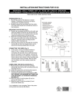
1.
Remove the diffuser from the body by removing the two screws.
2.
Release gear tray by removing the two retaining screws.
3.
Fix base to the ceiling. Use the bezel & fitting to ensure the ‘cutout’ is the correct size.
4.
ISOLATE THE A.C. SUPPLY and connect unit. An unswitched 240V A.C. supply must be connected to the
live (L). Earth and neutral (N) terminals on the PCB block. On Maintained circuits continuous illumination can
be achieved by connecting a link between L and Lsw either locally or through a remote switch.
5.
Plug battery lead into connector on the PCB.
6.
Resecure the gear tray into the base of the unit making sure that the mains cable is not trapped by the
PCB etc.
7.
Refit the diffuser using the two screws.
8.
Operational Check – Restore the A.C. Supply for 30 minutes and then remove. The LEDs should illuminate for at least 10 seconds.
9.
Restore the A.C. supply and check that the indicator LED is ‘on’.
ENSURE FITTING IS CHARGED FOR A MINIMUM OF 24 HOURS PRIOR TO TESTING
OPERATION
NON-MAINTAINED
Lamp normally off and battery on automatic charge (LED ‘on’) when A.C. Supply is healthy. Solid state circuitry
automatically switches lamp on when A.C. supply is interrupted.
MAINTAINED
Emergency lamp normally on, when the supply to L is switched on. The battery is on automatic charge (LED
‘on’). Lamp will switch on or remain on if A.C. Supply is interrupted.
MONITORING
Green indicator lamp (LED) normally continuously ‘on’. Indicator lamp goes out if A.C. Supply or charger fails.
BATTERY
Sealed Nickel-Cadmium rechargeable battery pack.
TEMPERATURE
Performance figures measured at 25 degrees C.
FAULT FINDING AND CORRECTIVE ACTION
MONITORING LED NOT ILLUMINATED
A.C. Supply not healthy. Battery not connected. Charger failed.
UNIT NOT MEETING REQUIRED EMERGENCY PERIOD
May need cycling: Discharge then recharge for 24 hours. Re-test, Battery pack may need replacing if emergency duration still not met.
LEDs NOT FULLY ILLUMINATED
If the LEDs are not illuminated check connections & if correct either the battery pack or (less likely) the printed
circuit board needs replacing.