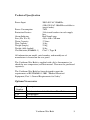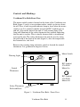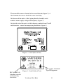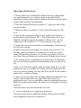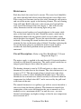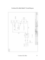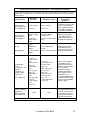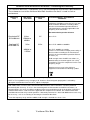
1
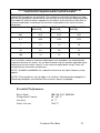
E M S P h ys i o L td .
Grove Technology Park
Downsview Road
Wantage
Oxfordshire OX12 9FE
England
User Manual
VARITHERM WAX BATH
Model 17
2
Varitherm Wax Bath
General Information
This manual provides the necessary information for the installation
and operation of the Varitherm Wax Bath.
These instructions must be studied before putting the unit into
operation.
The information contained in this manual is subject to change
without notice.
No part of this manual may be photocopied, reproduced or translated
into another language without the prior written consent of EMS
Physio Ltd.
It is intended that the Varitherm Wax Bath is only used by qualified
health professionals such as trained physiotherapists.
.
Record of Amendments
ISSUE
4
5
6
7
8
9
10
11
12
13
14
COMMENTS
CE Marking
Revised
Revised
Revised
Revised
Revised Company Name
Revised
EMC Tables Added
Revised
Info. for Thermal Switch added
& D of C amended.
Operating instructions updated
Varitherm Wax Bath
DATE
25/06/1998
19/05/1999
25/04/2000
10/09/2001
05/07/2005
04/10/2006
01/10/2007
05/02/2008
28/09/2010
27/09/2011
22/06/2012
3
EC Declaration of Conformity
EMS Physio Ltd
Grove Technology Park
Downsview Road
Wantage
Oxfordshire
OX12 9FE
United Kingdom
Declares that the following medical device is in conformity
with the essential requirements and provisions of Council
Directive 93/42/EEC and is subject to the procedure set out
in Annex 2 of Directive 93/42/EEC under the supervision of
Notified Body Number 0120, SGS United Kingdom Ltd.
Class IIb according to Annex IX of 93/42/EEC
Product Name
Varitherm Wax Bath
Model Number 17
Signature
Position
Quality Assurance Manager
Date
8 October 2011
Date first issued
6 May 1998
4
th
Varitherm Wax Bath
Contents
page
1
Title
General Information
3
Record of Amendments
3
Declaration of Conformity to 93/42/EEC
4
Contents
5
Warranty
6
Introduction
7
Contraindications
8
Precautions
8
Technical Specification
9
Installation
10
Controls and Markings
11
Operating Instructions
14
Maintenance
15
Circuit Description
15
Disassembly and Assembly
16
Parts List
18
Circuit Diagram
21
EMC Tables
22
Varitherm Wax Bath
5
Warranty
This EMS Physio Ltd., (hereinafter called the company) product is
warranted against defects in materials and workmanship for a period
of two years from the date of shipment. The Company will at its
option, repair or replace components which prove to be defective
during the warranty period, provided that the repairs or replacements
are carried out by the Company or its approved agents.
The Company will consider itself responsible for the effects on
safety, reliability and performance of the product:only if assembly operations, re-adjustments, modifications or
repairs are carried out by persons authorised by it,
only if the product is used in accordance with the instructions
for use,
only if the electrical installation of the relevant room complies
with the appropriate national requirements.
Should the product be returned to the Company for repair it must be
sent carriage paid.
Consumable items, for example, electrodes, electrode covers and
batteries, are excluded from the above warranty.
6
Varitherm Wax Bath
Introduction
Hot Wax therapy is one of several methods available to the therapist
of applying heat directly to the surface of the body. Paraffin Wax
supplied by EMS Physio Ltd melts at between 45° and 47° C. The
wax is held at a temperature just above its melting point and the part
of the body being treated is either immersed in the molten wax or the
wax is poured onto it. Heat is transferred from the wax to the
treatment area by thermal conduction.
Although temperatures above 45° may lead to skin damage under
normal circumstances, immersing a hand or foot in paraffin wax at
50° C is quite comfortable. Water or oil at the same temperature
would be uncomfortable and possibly damaging. However, when the
skin comes into contact with the molten wax, the wax immediately
next to the skin solidifies forming a thin insulating layer. This
insulating layer, which is of low thermal conductivity, lowers the
rate at which heat energy is applied to the skin to a level which is
safe.
The latent heat of fusion of the wax is released as the wax solidifies,
therefore, applying heat to the treatment area at constant
temperature. In normal treatment several layers of wax are applied
and further heat is released from the wax into the skin.
Another consequence of the solid layer of wax is that moisture is
prevented from being lost from the surface being treated. At the end
of treatment, when the wax is peeled off, the skin is left moist and
soft.
The Varitherm Wax Bath comprises a resin tank which holds the
paraffin wax, surrounded by an electrically heated, thermostatically
controlled water jacket. The temperature control may be set to
maximum in order to provide rapid melting of the solid wax when
the unit is first switched on. After almost all of the wax is melted, the
temperature control is normally set to approximately 50° C so that
the paraffin is just in its molten state. It is advisable to check the
actual wax temperature with a suitable thermometer prior to
treatment.
Varitherm Wax Bath
7
Contraindications
Areas with open wounds must not be treated.
Patients with skin infections as heat may increase inflammation.
Patients with reduced thermal sensation.
Precautions
Paraffin wax is inflammable. Its flash point is in excess of 200° C.
As the Varitherm Wax Bath heats the wax via a water jacket, heating
of the wax to dangerous temperatures is prevented. Should a fire
occur involving paraffin wax, CO2, dry powder or foam
extinguishers should be used. DO NOT USE WATER.
Wax spilt on floors can be extremely slippery. Spillages must be
dealt with promptly and completely.
Paraffin wax is a petroleum hydrocarbon and its molten state will
produce some fumes. Always use the Varitherm Wax Bath in a well
ventilated area. When not in use always cover the tank with the lid
provided.
8
Varitherm Wax Bath
Technical Specification
Power Input
Power Consumption
Protection Devices
Alarm Indicator
Size (H x W x D)
Water Capacity
Wax Capacity
Weight (empty)
Weight (fully loaded)
Classification (EN60601-1)
200-240 VAC 50/60 Hz
(100-120 VAC 50/60 Hz available to
special order)
3 kW
15A circuit breakers in each supply
line.
Red Neon Lamp
410 x 440 x 760 mm
17 litres
18 kg
23 kg
58 kg
Class 1, Type B
All information on model, serial number, and month/year of
manufacture is located on the rear panel.
The Varitherm Wax Bath is supplied with a lid, a thermometer (to
check the wax temperature) and this manual. Wax must be purchased
separately.
The Varitherm Wax Bath has been designed to meet the
requirements of BS EN60601-1:2001 “Medical Electrical
Equipment, Part 1: General Requirements for Safety”.
Optional Accessories
Catalogue
Number
LNC885
T1A
P11
Description
Tubular steel stand for Varitherm Wax Bath
Thermometer
Paraffin Wax
Varitherm Wax Bath
9
Installation
Upon receipt, check for any visible damage which may have
occurred in transit. If any signs of damage are found then retain all
packaging material and inform the carrier and the Company or its
agent from whom the unit was purchased.
If not already fitted, connect a suitable plug to the mains cable. The
plug must have provision for an EARTH (GROUND) connection.
The mains cable has the following colour code, BROWN is LIVE
(LINE), BLUE is NEUTRAL and GREEN/YELLOW is EARTH.
The Wax Bath lid is supplied, for ease of packaging, with the handle
on the reverse side. Remove the two screws holding the handle and
attach it to the correct side of the lid using the same screws.
The Varitherm Wax Bath must be positioned on a flat horizontal
surface or on the optional stand.
Lift the water filler cover and fill with tap water until the water level
is seen to be just above the inlet hole. The water capacity is
approximately 17 litres.
Fill the wax container with approximately 18 kg of paraffin wax. The
wax should be broken into small lumps to aid melting. Wax supplied
by EMS Physio Ltd. is strongly recommended as melting point and
correct operating temperature are highly dependent on the
composition of the paraffin wax.
Connect the Varitherm Wax Bath to a suitable mains oulet capable
of supplying at least 13A.
The Varitherm Wax Bath is now ready for use.
10
Varitherm Wax Bath
Controls and Markings
Varitherm Wax Bath Front View
The mains on/off switch is located on the front of the Varitherm wax
Bath (figure 1) and is a two-position rocker switch: up for on, down
for off. It has a built-in green indicator lamp to show when the mains
switch is on. It is marked with the recognised IEC Symbols for on
and off. Also on the front of the unit is a red warning lamp. This
lamp will illuminate if the safety thermostat has opened, indicating
that the unit is too hot. This is usually because there is insufficient
water in the unit. The safety thermostat can only be reset by using
the pull-cord at the front of the unit (figure 1) after the temperature
has returned to a safe level.
Between the warning lamp and mains switch is located the control
thermostat. It is graduated in degrees Celsius.
Mains Switch
Warning Light
IEC Symbol
878-01-01
Mains On
Control
Thermostat
IEC Symbol
878-01-02
Mains Off
Safety Thermostat
Pull-cord Reset
Figure 1 – Varitherm Wax Bath – Front View
Varitherm Wax Bath
11
Water filler cover
Wax Container
Mains
Circuit
Breakers
Warning
Light
Mains Switch
Temperature
Control
Mains Cable
Figure 2 – Varitherm Wax Bath – Top View
12
Varitherm Wax Bath
The water filler cover is located at the rear of the unit (figure 2). A
label reminds the user to check the water level daily.
On the rear of the unit is a label giving details of model, serial
number, mains supply voltage and frequency (figure 3).
On the left side of the unit is a label showing symbols from Class B
and Attention – consult accompanying documents (figure 4).
.
Figure 3 – Label (Rear of Unit)
Figure 4 – Label (Side of Unit)
IEC Symbol 348
Attention, consult
accompanying
documents.
Varitherm Wax Bath
IEC Symbol 878-02-02
Type B Equipment
13
Operating Instructions
1. Having filled the Varitherm Wax Bath with water and paraffin
wax and connected it to a suitable supply as described in the
installation section of this manual, switch on the unit using the mains
switch which will then be illuminated.
2. Turn the Control Thermostat to 60-65°C* and leave until all the
wax has melted.
3. When no solid wax remains, set the Control Thermostat to 5055°C.
4. Wait for the temperature of the wax to stabilise just above its
melting point (approximately 50°C). The temperature (of the wax)
should be checked using the thermometer. Please note – the wax
temperature will usually be 2-3 °C lower than the water temp.
5. Inspect the area to be treated for contraindications. Wash and dry
the area to be treated.
6. Immerse the part of the body to be treated in the wax for 2 or 3
seconds, and then withdraw it. A thin layer of solid wax will be
formed. Repeat this procedure 5 to 10 times to produce a layer of
wax about 3mm in thickness over the part of the body being treated.
7. The coating of wax is normally left in place for 15 to 20 minutes.
The wax may then be peeled off and returned to the wax bath for reuse.
8. For areas of the body which cannot be immersed in the wax tank,
molten wax may be carefully and slowly poured or ladled on to the
area to be treated, making sure that wax that runs off the area can be
collected in a suitable container.
9. After several treatments, dirt and other undesirable impurities may
collect at the bottom of the wax tank. When this reaches an
unacceptable level, the wax should be removed and purified using an
EMS wax purifier which allows the lower layers of impure wax to be
removed.
10. Daily check the water level in the wax bath.
11. Always check the wax temperature before use.
*In more recent units an additional thermal switch ensures that the
water temperature can never exceed 65°C.
Maintenance
Each day check the water level is correct. The water level should be
just above the inlet hole when viewed through the water-filler cover.
If the water level becomes too low the safety thermostat will operate
and cut off the mains supply to the heating element. The red warning
lamp will light. Refill with water to the correct level and pull the
reset cord at the bottom of the unit (figure 1). This will reset the
safety thermostat and the red warning light will go out.
The mains circuit breakers are located adjacent to the mains cable
entry at the front right of the unit. Should the mains switch not be
illuminated when in the on position, check to see if either of the
circuit breakers has tripped. To reset the circuit breakers push them
in firmly. If resetting the circuit breakers does not correct the fault,
examine the fuse in the mains plug (if fitted). If neither replacing the
fuse in the mains plug nor resetting the mains circuit breakers
rectifies the fault then qualified service personnel should be
contacted.
Circuit Description - Refer to the Wax Bath Model 17 Circuit
Diagram on Page 21.
The mains supply is applied to the unit through 15A circuit breakers
in both live and neutral connections. The mains on/off switch has an
integral green lamp to show when the power is on.
The heating element is rated at 3 kW and carries a safety cut-out
thermostat in a tube close to the element. The safety thermostat is set
to open at 75°C. The red warning lamp is wired across the safety
thermostat so that it will be illuminated should it open. The safety
thermostat has a manual reset which can only be activated when the
temperature has fallen below 60°C and is accessed by the pull-cord
at the front of the unit.
The control thermostat is a capillary type with its sensor located in a
tube away from the heating element. This thermostat controls the
temperature of the water and therefore the wax in normal use. It is
normally set to a maximum of 60°C to melt the wax – an extra
thermal switch limits any higher settings so that the wax temperature
never exceeds 65°C.
Varitherm Wax Bath
15
Disassembly and Assembly
Replacing the Wax Tank (24-50A)
1.
2.
3.
4.
Remove the two grub screws securing the wooden surround.
Remove the wooden surround (24-50B).
Remove the wax tank (24-50A).
Inspect the rubber seal (15-45) around the edge of the copper
tank and replace if damaged or perished.
5. Insert the new tank, replace the wooden surround and secure
with the two screws.
Replacing the Safety Thermostat (24-57)
1. Remove the four screws which secure the front cover and
remove the cover itself.
2. Remove the two M3 screws which secure the fibreglass plate to
the metal bracket attached to the element.
3. Remove the red and black wires from the screw terminals on the
thermostat.
4. Withdraw the safety thermostat from its tube.
5. Fit the new thermostat, connect the red and black wire to the
screw terminals on the thermostat.
6. Check the water level is correct and set the control thermostat to
60°C. Set the safety thermostat to its maximum position.
7. Connect the mains supply and wait for the water to reach the set
temperature.
8. Reduce the setting of the safety thermostat until it opens and the
red warning light comes on.
9. Increase the setting of the safety thermostat to about 75°C and
pull the reset cord. The warning light should go out.
10. Switch off the unit and replace the front cover with its four
fixing screws.
16
Varitherm Wax Bath
Element/Thermostat Assembly
The original heating element and cut out thermostat for Wax Baths
prior to serial number 70074 are no longer available.
For these earlier Wax Baths the complete Element/Thermostat
assembly part number C17-41 must be used whenever either the
heating element or cut out thermostat are required to be replaced.
Fitting of replacement element/Thermostat Assembly
For wax baths serial number 70074 onwards the element assembly
part number 60-66 and cut out thermostat part number 24-83 are
direct replacements for the original components.
For wax baths prior to serial number 70074 follow the procedure
below for installation of the combined replacement element
assembly part number C17-41 (this assembly includes the cut out
thermostat).
1. Remove the wires linking the old assembly to the wiring loom
and unscrew the assembly from the tank.
2. Fit the new element assembly C17-41 to the wax bath tank.
3. Undo the two M3 screws holding the reset plate and swing it to
the right exposing the screw for the left hand terminal in the
thermostat housing.
4. Refit the black wire to the left hand terminal and refit the reset
plate into position (the red wire from the 3 way terminal to the
cut-out thermostat has been fitted at the factory).
5. The previously removed red wire (step 1) must now be extended
by unwrapping part of its length from the wiring loom to enable
it to be plugged into the tag on the new element assembly.
6. Refer to the instructions on page 16 for the safety thermostat
temperature setting.
Varitherm Wax Bath
17
LNC884
VARITHERM WAX BATH
Part No.
Description
Qty
40-85
7-1
A17-23
OM884EN
T1A
WAX BATH
HANDLE BLACK NYLON
WAX BATH LID
OPERATING MANUAL
THERMOMETER
1
1
1
1
1
40-85
WAX BATH
Part No
Description
10-41
15-45
17-30B
17-49
19-3
2-24
2-73
24-50A
24-50B
24-51
24-52
24-53B
24-97
24-55B
24-57
24-59
24-83
31-66
33-18
33-25
33-30
33-31
33-37A
33-46A
33-48
Part No
PLUG TOP 13A
RUBBER EXTRUSION
SWITCH ROCKER GREEN
TERMINAL BLOCK 4WAY
CABLE TIE T18R
SPIRAP 6mm
CASTOR 2" RUBBER TYRE
WAX BATH INNER TANK
WOODEN SURROUND C/T
BACK NUT 2-1/4" BSP
BACK NUT 1/2" GAS
WATER FILLER MOULDED
THERMOSTAT CAPILLARY
ESCUTEON BEZEL
POCKET THERMOSTAT
BALL VALVE SEAT
THERMAL CUT OUT
CHROME SPACER
SCREW M3 x 10 PAN HD
SCREW M4 x 8 C/SUNK
SCREW M4 x 10mm
SCREW M4 x 10mm
SCREW M4 x 20mm
SCREW M5 x 40 C/SUNK
SETSCREW M6 x 30 HEX
Description
33-50
SCREW M8 x 16 HEX HD
18
Varitherm Wax Bath
Qty
1
182cm
1
1
3
100cm
4
1
1
1
1
1
1
1
1
1
1
2
3
1
10
4
1
2
2
Qty
8
34-1
34-22
34-23
34-24
34-34
34-42
34-43
34-45A
35-30
35-4
36-10
36-7
39-37
39-47
60-66
7-18A
7-4A
A17-15
A17-28
A17-32
A17-35
A17-38
A17-39
A17-43
A17-50
B17-4
B17-5
B17-9
C126
C17-6
C184
C39
C41
C59
C82
G6
Part No
WASHER M3 PLAIN
WASHER M3 BERYLLIUM
WASHER M4 BERYLLIUM
WASHER M6
M8 INTERNAL S/PRF
NUT M3 HEX
NUT M4
NUT M8
WASHER 2BA HEAVY
SCREW 2BA x 3/8 HEX HD
GRUB SCREW 4BA x ¼
SCREW 4BA x ¼ C/SUNK
WASHER 5/16 HEAVY
FIBRE WASHER 38mm OD
ELEMENT MODIFIED
NEON INDICATOR
HANDLE HAF 525
FRONT PANEL
KNOB ASSEMBLY THERMOSTAT
COPPER WASHER
SPACER
THERMOSTAT RET.BRK’T
THERMOSTAT RESET PT.
INSULATOR
LABEL SET
FRONT CASTOR PLATE
REAR CASTOR PLATE
COPPER WATER TANK
CABLE BLACK MAINS
OUTER CASE
P CLIP RICHCO NE6
CABLE BLACK 63/0.2
CABLE RED 63/0.2
NYLON BRAIDED CORD
CABLE GRN/YEL 63/0.2
GROMMET 3028 3/8"
Description
G30
L106
L57A
L78
CABLE STRAIN RELIEF
L E N LABEL
LABEL “PER No. BATCH”
LABEL “EARTH SYMBOL”
Varitherm Wax Bath
6
3
21
2
4
6
3
4
2
2
2
1
8
1
1
1
1
1
1
1
1
1
1
1
1
1
1
1
350cm
1
1
190cm
162cm
30cm
54cm
1
Qty
1
1
1
1
19
L94
P2
R10
R18
S144
S35
T100
T11A
T28
T40A
T50
T67
LABEL “POWER”
PLASKLIP 5/16
POP RIVET TSP/D 435
RIVET BUTT HD NO.16
HEAT TRANSFER COMPOUND
SLEEVING YELLOW 3mm
TAG, RING YELLOW
TERMINAL 42095-1
TERM BOOT 154509-2
2BA BLUE RING TAG
TERMINAL 41729-2
BRASS TAB
Spare Parts Only:B17-37
C17-42
20
WATER FILLER ASSEMBLY
COMPLETE CABLE ASSEMBLY
Varitherm Wax Bath
1
1
2
14
25ml
5cm
2
1
17
3
16
1
Varitherm Wax Bath Model 17 Circuit Diagram
Varitherm Wax Bath
21
EMC Tables
1
2
3
4
6
7
8
22
Guidance and manufacturers declaration – electromagnetic emissions
The Varitherm Wax Bath is intended for use in the electromagnetic
environment specified below. The customer or the user of the Varitherm
should assure that it is used in such an environment.
Electromagnetic environment Emissions Test
Compliance
guidance
The Varitherm generates negligible RF
emissions (switching of thermostat).
RF emissions
Therefore, its RF emissions are very
Group 1
CISPR 11
low and are not likely to cause any
interference in nearby electronic
equipment.
RF emissions
Class A
CISPR 11
Harmonic
The Varitherm is suitable for use in all
emissions
Class A
establishments other than domestic and
IEC 6100-3-2
those directly connected to the public
low-voltage power supply network that
Voltage
supplies buildings used for domestic
fluctuations
purposes.
Complies
Flicker emissions
IEC 61000-3-3
Varitherm Wax Bath
Guidance and manufacturers declaration – electromagnetic immunity
The Varitherm Wax Bath is intended for use in the electromagnetic environment specified
below. The customer or the user of the Varitherm should assure that it is used in such an
environment.
Immunity test
Electrostatic
discharge (ESD)
IEC 61000-4-2
Electrical fast
transient/burst
IEC61000-4-4
Surge
IEC61000-4-5
IEC 60601
test level
±6 kV contact
±6 kV contact
±8 kV air
±8 kV air
±2 kV for
power supply
lines
±2 kV for power
supply lines
±1 kV for
input/output
lines
±1 kV
differential
mode
±2 kV common
mode
<5% UT
(>95% dip in
UT)
For 0,5 cycle
Voltage dips,
short
interruptions and
voltage
variations on
power supply
input lines
IEC 61000-4-11
Compliance level
40% UT
(60% dip in
UT)
For 5 cycles
70% UT
(30% dip in
UT)
For 25 cycles
<5% UT
(>95% dip in
UT)
For 5 sec
±1 kV for input/output
lines
±1 kV differential
mode
±2 kV common mode
<5% UT
(>95% dip in UT)
For 0,5 cycle
40% UT
(60% dip in UT)
For 5 cycles
70% UT
(30% dip in UT)
For 25 cycles
<5% UT
(>95% dip in UT)
For 5 sec
Electromagnetic
Environment
guidance
Floors should be wood,
concrete or ceramic tile.
If floors are covered
with synthetic material,
the relative humidity
should be at least 30%.
Mains power quality
should be that of a
typical commercial or
hospital environment.
Mains power quality
should be that of a
typical commercial or
hospital environment.
Mains power quality
should be that of a
typical commercial or
hospital environment. If
the user of the
Varitherm requires
continued operation
during power mains
interruptions, it is
recommended that the
Varitherm be powered
from an uninterruptible
power supply.
Power frequency
magnetic field should be
at levels characteristic
3 A/m
3 A/m
of a typical location in a
typical commercial or
hospital environment.
NOTE UT is the a.c. mains voltage prior to application of the test level.
Power frequency
(50/60 Hz)
Magnetic field
IEC 61000-4-8
Varitherm Wax Bath
23
Guidance and manufacturers declaration – Electromagnetic immunity.
The varitherm Wax Bath is intended for use in the electromagnetic environment specified below.
The customer or user of the Varitherm Wax Bath should assure that it is used in such an
environment.
Immunity
Test
IEC 60601
Test level
Compliance
level
Electromagnetic Environment
Guidance
Portable and mobile RF communications
equipment should be used no closer to any part
of the Varitherm Wax Bath, including cables,
than the recommended separation distance
calculated from the equation applicable to the
frequency of the transmitter.
Recommended separation distance
Conducted RF
IEC61000-4-6
3Vrms
150kHz to
80MHz
3V
Radiated RF
IEC61000-4-3
3V/m
3V/m
80MHz to
2.5GHz
d=3.5√P/V1
d=3.5√P/E1 80MHz to 800MHz
d=7√P/E1 800MHz to 2.5GHz
where P is the maximum output power rating of
the transmitter according to the manufacturer
and d is the recommended separation distance
in metres (m).
Field strengths from fixed RF transmitters, as
determined by an electromagnetic site surveya
should be less than the compliance level in each
frequency rangeb.
Interference may occur in the vicinity of
equipment marked with the following symbol:
NOTE 1 At 80MHz and 800MHz the higher frequency range applies.
NOTE 2 These guidelines may not apply in all situations. Electromagnetic propagation is affected by
absorption and reflection from structures, objects and people.
a
Field strengths from fixed transmitters, such as base stations for radio (cellular/cordless) telephones and
land mobile radios, amateur radio, AM and FM radio broadcast and TV broadcast cannot be predicted
theoretically with accuracy. To assess the electromagnetic environment due to fixed RF transmitters, an
electromagnetic site survey should be considered. If the measured field strength in the location in which the
Varitherm Wax Bath is used exceeds the applicable RF compliance level above, the Varitherm Wax Bath
should be observed to verify normal operation. If abnormal performance is observed additional measures may
be necessary, such as re-orienting or relocating the Varitherm Wax Bath.
b
Over the frequency range 10kHz to 80Mhz, field strengths should be less than 3 V/m.
24
Varitherm Wax Bath
Recommended separation distances between portable and mobile RF
communications equipment and the Varitherm Wax Bath
The Varitherm Wax Bath is intended for use in an electromagnetic environment in which
radiated RF disturbances are controlled. The customer or user of the Varitherm can help
prevent electromagnetic interference by maintaining a minimum distance between portable
and mobile RF communications equipment (transmitters) and the Varitherm Wax Bath as
recommended below, according to the maximum output power of the communications
equipment.
150kHz to 80MHz
d=3.5√P/V1
80MHz to 800MHz
d=3.5√P/E1
0.01
0.12
0.12
0.23
0.1
0.38
0.38
0.73
1
1.2
1.2
2.3
10
3.8
3.8
7.3
100
12
12
23
800MHz to 2.5GHz
d=7√P/E1
For transmitters rated at a maximum output power not listed above, the recommended
separation distance d in meters (m) can be estimated using the equation applicable to the
frequency of the transmitter, where P is the maximum output power rating in watts (W)
according to the transmitter manufacturer.
NOTE 1 At 80MHz and 800MHz the separation distance for the higher frequency range
applies.
NOTE 2 These guidelines may not apply in all situations. Electromagnetic propagation is
affected by absorption and reflection from structures, objects and people.
Essential Performance
Power Input
Temperature Control
Accuracy
Safety Cut-out
200-240 VAC 50/60 Hz
20 – 60 °C
±5 °C
75±5°C
Varitherm Wax Bath
25