1
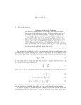
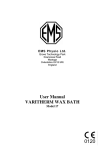
INSTALLATION &
OPERATION MANUAL
VGL SERIES GAS STEAM KETTLES
MODEL
VGL20
VGL40
VGL60
VGL20E
VGL40E
VGL60E
MODEL VGL40
VULCAN-HART
FORM 30909 (1-95)
COMPANY,
P.O.
BOX
696,
LOUISVILLE,
KY
40201-0696,
TEL. (502) 7 7 8 - 2 7 9 1
IMPORTANT FOR YOUR SAFETY
THIS MANUAL HAS BEEN PREPARED FOR PERSONNEL QUALIFIED TO INSTALL GAS
EQUIPMENT, WHO SHOULD PERFORM THE INITIAL FIELD START-UP AND
ADJUSTMENTS OF THE EQUIPMENT COVERED BY THIS MANUAL.
POST IN A PROMINENT LOCATION THE INSTRUCTIONS TO BE FOLLOWED IN THE
EVENT THE SMELL OF GAS IS DETECTED. THIS INFORMATION CAN BE OBTAINED
FROM THE LOCAL GAS SUPPLIER.
IMPORTANT
IN THE EVENT A GAS ODOR IS DETECTED, SHUT DOWN
UNITS AT MAIN SHUTOFF VALVE AND CONTACT THE
LOCAL GAS COMPANY OR GAS SUPPLIER FOR
SERVICE.
FOR YOUR SAFETY
DO NOT STORE OR USE GASOLINE OR OTHER
FLAMMABLE VAPORS OR LIQUIDS IN THE VICINITY OF
THIS OR ANY OTHER APPLIANCE.
WARNING: IMPROPER INSTALLATION, ADJUSTMENT,
ALTERATION, SERVICE OR MAINTENANCE CAN CAUSE
PROPERTY DAMAGE, INJURY OR DEATH. READ THE
INSTALLATION, OPERATING AND MAINTENANCE
INSTRUCTIONS THOROUGHLY BEFORE INSTALLING OR
SERVICING THIS EQUIPMENT.
IN THE EVENT OF A POWER FAILURE, DO NOT
ATTEMPT TO OPERATE THIS DEVICE.
–2–
Installation, Operation, and Care of
VGL SERIES GAS STEAM KETTLES
SAVE THESE INSTRUCTIONS FOR FUTURE USE
GENERAL
The VGL Series Gas Steam Kettles use efficient gas heat and thermostat controls to provide superior
cooking performance. The VGL Kettles are intended for commercial use only; not for household use.
If the VGL kettle's model designation ends in E, the unit is provided with electronic ignition instead of
a pilot light. The VGL kettles are stationary, self-contained, and come fully assembled from the factory.
CAPACITY and GAS RATINGS
Model
VGL20,VGL20E
VGL40,VGL40E
VGL60,VGL60E
Capacity
20 gallons
40 gallons
60 gallons
BTU Rating
100,000 BTU/hr
100,000 BTU/hr
130,000 BTU/hr
INSTALLATION
UNPACKING
Uncrate carefully. Immediately after unpacking, check for possible shipping damage. If the steam
kettle is found to be damaged, save the packaging material and contact the carrier within 15 days of
delivery.
Before installing, verify that the gas (natural or propane), the elevation from sea level, and the electrical
supply agree with the specifications on the rating plate which is located on the lower right side. NOTE:
if this kettle is being installed above 2000 feet altitude, contact your Vulcan-authorized service office
to assure that the proper orifice size for your elevation has been installed.
LOCATION
The installation location must be kept free and clear of combustibles. Clearance from combustible
construction must be a minimum of 6 inches from the sides, 2 inches from the back (at the flue box),
and 6 inches from the floor (as provided by legs). Provide adequate clearances for cleaning,
maintenance, service and proper operation.
The installation of the appliance should not obstruct the flow of combustion and ventilation air.
Sufficient air should be allowed to enter the room to compensate for the amount of air removed by any
ventilating system and for combustion of the gas burners. Do not permit fans to blow directly on the
appliance and avoid open windows at the sides or back. Avoid wall type fans which create air cross
currents within the room. Do not obstruct the air flow into and around the appliance. Do not obstruct
the flow of flue gases from the flue duct located on the rear of the appliance. It is recommended that
the flue gases be ventilated to the outside of the building through a suitable and properly installed
ventilation system.
–3–
LEVELING THE APPLIANCE
To level the kettle, use a spirit level in all directions on the top of the kettle with the lid up.
Units with legs — adjust the bottom foot in each leg to overcome an uneven floor.
INSTALLATION CODES AND STANDARDS
The steam kettle must be installed in the United States in accordance with: 1) State and local codes;
2) National Fuel Gas Code, ANSI-Z223.1, latest edition, available from American Gas Association,
1515 Wilson Boulevard, Arlington, VA 22209; and 3) National Electrical Code, ANSI/NFPA No. 70,
latest edition, and with NFPA Standard #96, Vapor Removal from Cooking Equipment, latest edition,
available from the National Fire Protection Association, Batterymarch Park, Quincy, MA 02269.
VENTILATION HOOD
The steam kettle must be installed under a suitable ventilation hood.
PRESSURE RELIEF VALVE
The pressure relief valve is located at the right rear of the unit. This area should be kept clear and
should not be in an area where operators will normally stand. The elbow on the relief valve should be
turned toward the floor. A maximum 3 foot, 3/4" diameter pipe may be used to extend to the floor, but
must not be piped directly to a drain — it must vent to the atmosphere.
PRESSURE GAUGE
Check the pressure gauge on the front panel before operating. If the pressure gauge does not indicate
20 to 30 inches of mercury column vacuum, contact your authorized Vulcan-authorized servicer to reestablish the vacuum.
WATER CONNECTION
Steam kettles equipped with an optional water fill valve should be connected to the water supply line
(minimum 1⁄4") at the 1⁄4" NPT internal threaded fitting on the valve. Units with dual (hot and cold)
valves must have the hot water line connected to the side with the hot water valve (red) and cold water
line to the cold water valve (blue). Plastic or rubber hose is not recommended as it may melt against
the hot kettle side.
–4–
GAS CONNECTION
The data plate on the lower right side of the kettle indicates the type of gas your unit is equipped to burn.
DO NOT connect to any other gas type.
A 1" NPT line is provided at the rear for the connection. Each kettle is equipped with an internal
pressure regulator which is set for 4" W.C. manifold pressure for natural gas or 10" W.C. for propane
gas. Use the 1/8" pipe tap on the burner manifold for checking pressure.
An adequate gas supply is necessary. Undersized or low pressure lines will restrict the volume of gas
required for satisfactory performance. A maximum supply pressure of 8" W.C. for natural gas and 13"
W.C. for propane gas is recommended. With all units operating simultaneously, the manifold pressure
on all units should not show any appreciable drop. Fluctuations of more than 25% on natural gas, and
10% on propane gas, will create pilot problems and affect burner operating characteristics. Contact
your gas company for correct supply line sizes.
Purge the supply line to clean out any dust, dirt, or any foreign matter before connecting the line to the
unit.
Caution: The pipe thread compound used when installing pipes must be a type that is resistant
to the action of liquified petroleum or propane gases.
Codes require that a gas shut-off valve be installed in the gas line prior to the kettle. Make sure the
pipes are clean and free of obstructions, dirt, and piping compound.
TESTING THE GAS SUPPLY PIPING
When test pressures exceed 1/2 psig (3.45 kPa) the steam kettle and its individual shut-off valve must
be disconnected from the gas supply piping system during any pressure testing of the system. When
test pressures are 1/2 psig (3.45 kPa) or less, the kettle must be isolated from the gas supply piping
system by closing its individual shut-off valve during any pressure testing of the system.
WARNING: PRIOR TO START-UP, CHECK ALL JOINTS IN THE GAS SUPPLY LINE FOR LEAKS.
USE SOAP AND WATER SOLUTION. DO NOT USE AN OPEN FLAME.
Do not connect the kettle to the electrical supply until after the gas connection has been made.
–5–
ELECTRICAL CONNECTION
Refer to the electrical diagram attached to the inside of the front panel and to ELECTRICAL DATA.
ELECTRICAL DATA
MODEL
VGL Series
Volts / Hz / Ph
Standard / Optional
Amps
Circuit Requirement
115 / 60 / 1
Standard
2.0
15 Amp Cord/Plug
208 / 60 / 1 or 3
Optional
1.0
Hard wire
236 / 60 / 1 or 3
Optional
1.0
Hard wire
Cord Connected Steam Kettles
WARNING: THE SUPPLY CORD ON THE STEAM KETTLE IS PROVIDED WITH A GROUNDING
PLUG. THE OUTLET TO WHICH THIS PLUG IS CONNECTED MUST BE PROPERLY GROUNDED.
IF THE RECEPTACLE IS NOT THE PROPER GROUNDING TYPE, CONTACT AN ELECTRICIAN.
Hard Wire Connected Steam Kettles
WARNING: ELECTRICAL AND GROUNDING CONNECTIONS MUST COMPLY WITH THE
APPLICABLE PORTIONS OF THE NATIONAL ELECTRICAL CODE AND/OR OTHER LOCAL
CODES.
WARNING: DISCONNECT THE ELECTRICAL POWER SUPPLY AND PLACE A TAG AT THE
DISCONNECT SWITCH INDICATING THAT YOUR ARE WORKING ON THE CIRCUIT.
Units equipped for 208 or 236 volt / 60 Hz, single- or three-phase electrical service, are factory
equipped with a transformer. To connect supply wires, remove the cover from the transformer box at
the right rear of the unit. Route supply wires and ground wire through the hole in the cover with a strain
relief fitting. Connect wires to the primary transformer terminals as required by your power supply
voltage. Connect ground wire to the ground lug. Replace cover. Three-phase units are wired as
above, using only two supply wires. The third supply wire is not connected and must be properly
terminated.
PERFORMANCE CHECK
The following items should be checked at installation by a qualified service technician.
1. Verify correct gas type.
2. Verify correct voltage, cycle and phase.
3. Gas pressure.
4. Internal gas connections.
5. Internal electrical connections.
6. Pilots — adjustment and ignition.
7. Burners — adjustment and ignition.
8. Thermostat — cycle for operation check.
9. Gas supply valve — check for operation.
10. Check hinge and lid assembly.
11. Draw-off valve — check operation.
12. Advise user on cleaning procedures.
–6–
USING THE GAS CONTROL (Kettles with Pilot Lights)
A. Lighting
1. Turn thermostat to lowest position and turn the power switch OFF.
2. Open control panel access door.
3. Turn dial on combination control to pilot position. NOTE: Any gas service valves exterior to the
unit should be open.
4. Remove shield which fits over the burners for access to the pilot, which is located on the right
side of the left burner, approximately 6" into the combustion chamber. Depress dial on the
combination control while lighting the pilot burner. Hold dial in for 30 - 45 seconds, until the pilot
remains lit when the dial is released. A lit taper is recommended for easy access in lighting the
pilot burner.
On units recently installed, the pilot line will require "bleeding". Consequently, the pilot may not
ignite immediately and it may be necessary to keep the combination control dial depressed until
sufficient gas reaches the pilot to keep it burning. After "bleeding" wait 5 minutes before
attempting ignition.
5. Turn combination control dial ON.
B. Shut Down
1. Standby
a. Turn combination control to "pilot" position.
2. Complete
a. Depress lightly and turn combination control dial OFF.
b. Turn thermostat to lowest position.
c. Turn power switch OFF.
d. Turn any gas service valves supplying gas OFF.
C. Relighting
1. Shut off all gas (turn combination control OFF.)
2. Wait 5 minutes.
3. Repeat "lighting" instructions in section A above.
–7–
USING THE GAS CONTROL (Kettles with Electronic Ignition)
Units equipped with electronic ignition do not require "lighting" the pilot with a match.
A. Lighting
1. Turn thermostat to lowest position and turn the power switch OFF.
2. Open control panel access door.
3. Turn dial on combination control to ON position by rotating the control knob counterclockwise
to "stop" on black line. Depress control knob completely and release, then continue to rotate
to ON. (NOTE: Any gas service valves exterior to the unit should be open.)
4. Turn power switch ON.
After step 4 there will be a 2 minute and 10 second delay before the kettle will attempt ignition. At this
time the spark igniter will begin sparking at the pilot until the pilot is ignited, or for 50 seconds (an
audible clicking sound will be evident).
After a total of 3 minutes the unit will lockout, shutting off all gas although the spark igniter will continue
to spark. When the pilot is ignited the spark igniter will automatically stop and within 30 to 60 seconds
main burner gas will come on if the thermostat is turned on. New installations (where there may be a
considerable amount of air in the gas line) may require the unit to be turned off and immediately back
on numerous times after each 3 minute lockout period until the air is purged from the gas line.
B. Shut Down
1. Standby
a. Turn power switch OFF.
2. Complete
a. Turn power switch OFF.
b. Turn dial on combination control from ON to black line, depress knob slightly and continue
rotating to OFF.
c. Place thermostat on lowest setting.
d. Turn any main gas service valves supplying gas to OFF.
C. Relighting
1. Turn power switch ON.
It should be noted that the pilot and electronic ignition do not cycle with the thermostat. A standing pilot
is automatically established and monitored each time the power switch is turned on. If the pilot is ever
extinguished by a momentary external interruption, the spark igniter will automatically relight it after
a 2 minute and 10 second purge period without disturbing the cooking cycle, unless lockout occurs.
–8–
OPERATION
WARNING: THE STEAM KETTLE AND ITS PARTS ARE HOT. USE CARE WHEN OPERATING,
CLEANING, AND SERVICING THE STEAM KETTLE.
CONTROLS (Figs. 1, 2)
POWER
OFF
ON
Main Power Switch — Turns main power ON or OFF.
Switch must be turned ON to heat the kettle. Turn the
switch OFF when the kettle will not be in use for long
periods.
COOKING
LOW WATER
COOK TEMP.
(Red) Cooking Light — This light is on whenever the
main burner gas is on. On units with electronic ignition,
this light may be on without the burners being on if the
standing pilot becomes extinguished — see page 8.
▼
(Amber) Low Water Light — All kettles are supplied with
OFF
OFF
PRESSURE
WATER LEVEL
sufficient distilled water inside the pressurized jacket. If
at any time the water level falls below that required for
proper operation, the kettle will not heat and this light will
come on. Contact your Vulcan-authorized servicer to
have water added to the jacket and to have the vacuum
pressure re-established.
Thermostat — Sets the kettle's internal operating
temperature (150 – 285°F) or OFF.
Pressure Gauge — Indicates the internal operating
pressure of the kettle. When cold, the gauge should
indicate 25 to 30 inches mercury column vacuum. If it
does not, contact your Vulcan-authorized servicer. Under
normal operation with the kettle empty (and the thermostat
set to 285°F) the pressure shall reach 38 psig. When
loaded the pressure may be considerably less.
Fig. 1
Water Level (Sight Glass) — Indicates the minimum and
maximum water level in the pressurized internal portion
of the kettle. If the water level falls below the minimum
level, contact your Vulcan-authorized servicer.
Controls
Draw-Off Valve
Lid
Kettle Tank
Pressure Relief Valve — This device is located inside
and prevents the internal kettle pressure from exceeding
50 psig. It should never be tampered with.
Jacket
Steam (Pressurized)
Water Level
Burner
12345678901234567890123
12345678901234567890123
12345678901234567890123
12345678901234567890123
12345678901234567890123
12345678901234567890123
12345678901234567890123
Fig. 2
Draw-Off Valve — Allows you to empty the contents of
the kettle into a suitable container. USE CARE WHEN
HANDLING HOT FOOD. Soups with large chunks may
need to be ladled.
–9–
DAILY OPERATION
Daily operation should consist of turning on the power switch and setting the thermostat for the desired
temperature.
It is recommenced the kettle be preheated empty prior to use. Milk or egg based products should be
placed in the kettle before heating, however, to prevent sticking. The kettle is preheated when the
cooking light goes off for the first time.
At the end of each day, or if the kettle will not be used for some time, shut the unit down by turning the
power switch OFF.
Clean as required or on a daily basis. Refer to Cleaning, page 11.
On standing pilot units the burner will ignite as soon as both the power switch and the thermostat are
turned on.
On electronic ignition units, turning on the power switch initiates a pilot lighting sequence. For the first
2 minutes and 10 seconds nothing will happen. After 2 minutes and 10 seconds the spark igniter will
begin sparking. The spark igniter will spark until the pilot is ignited. After a total of 3 minutes (or 50
seconds after the spark igniter begins) lockout will occur. Lockout shuts down all pilot (and main
burner) gas flow although the spark igniter will continue to spark. The power switch must be turned
off and back on to restart the pilot lighting sequence once lockout has occurred.
If the pilot blows out during operation, the unit will go through the same sequence to re-ignite itself.
Once the pilot is ignited, another 15 to 45 seconds is required to heat the flame switch before main
burner gas will flow if the thermostat is turned on.
OPERATOR TIPS
For easier cleaning add cold water to the kettle immediately after removing contents.
When preparing foods containing vinegar or tomatoes, or those which have a high salt content, clean
the kettle immediately after using to prevent pitting.
Do not use salt to clean the kettle. This will scratch the surface.
If using saltwater to cook shellfish, be sure to rinse and wash the kettle thoroughly.
Bring milk and egg products slowly up to temperature in a cold kettle to prevent product adhering to
the sides.
When planning actual cooking capacity, allow room at top for stirring without spilling.
When preparing milk-based products do not preheat the kettle. This will prevent the milk from sticking
to the sides.
When preparing puddings from a mix, place the powder in a cold kettle, add a small amount of the liquid,
and stir to form a thin paste. Turn on the kettle and add the remainder of the liquid. Continue per recipe
instructions.
When browning meat bring the kettle up to temperature before adding. This seals the juices in the
meat.
– 10 –
CLEANING
WARNING: DISCONNECT ELECTRICAL POWER BEFORE CLEANING.
Clean inside the kettle daily by wiping with a clean damp cloth. Clean the exterior daily with soap and
detergent and water. Rinse thoroughly and wipe dry with a soft clean cloth.
Monthly — Clean around burner air mixers, louvered panels and pilots if grease or lint have
accumulated.
SPECIAL CLEANING PROCEDURES
Cleaning Stainless Steel — To remove normal dirt, grease or product residue from stainless steel,
use ordinary soap and water (or detergent); apply with a sponge or cloth. Dry thoroughly with a clean
cloth. Never use vinegar or any corrosive cleaner.
To remove grease and food spatter or condensed vapors that have baked on the equipment, apply
cleanser to a damp cloth or sponge and rub cleanser on the metal in the direction of the polishing lines
on the metal. Rubbing cleanser as gently as possible in the direction of the polished lines will not mar
the finish of the stainless steel. NEVER RUB WITH A CIRCULAR MOTION. Soil and burnt deposits
which do not respond to this procedure can usually be removed by rubbing the surface with ScotchBrite
scouring pads or stainless steel scouring pads. Do not use ordinary steel wool or steel scouring pads
as any particles left on the surface will rust and further spoil the appearance of the finish. Never use
a wire brush, metal scraper, file or other steel tools. Surfaces which are marred collect dirt more rapidly
and become more difficult to clean. Marring also increases the possibility of corrosive attack.
Refinishing may then be required.
Removing Heat Tint — Darkened areas sometimes appear on stainless steel surfaces where the area
has been subjected to excessive heat. Heat tint can normally be removed by the stainless steel
cleaning procedure, however, tint which does not respond to this procedure calls for a vigorous
scouring in the direction of the polish lines using ScotchBrite scouring pads or a stainless steel scouring
pad in combination with a powdered cleanser. Heat tint action may be lessened by not applying or by
reducing heat to equipment during slack periods.
All food contact surfaces must be thoroughly drained and flushed prior to cooking in the kettle.
Control Panel — The textured control panel should be cleaned with a damp cloth moistened in warm
soapy water. Never use an abrasive cloth or steel wool. Never use cleaning solvents with a
hydrocarbon base.
Vent System — At least twice a year the exhaust hood (venting system) should be examined and
cleaned.
Tips for Efficient Operation — Turn kettle off when not in use. Limit preheat times. Use the lid
whenever possible. Follow proper cleaning and maintainance procedures.
Operational Performance Check — To bring 12 gallons of water from 60°F to 212°F, starting the
kettle from a cold start, should take about 28 to 32 minutes.
SERVICE
Contact your local Vulcan-authorized servicer for any repairs or adjustments needed on this equipment.
– 11 –
FORM 30909 (1-95)
– 12 –
PRINTED IN U.S.A.