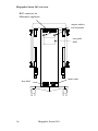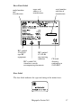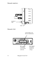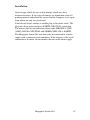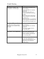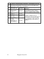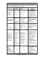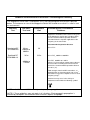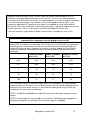
1
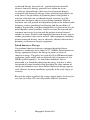
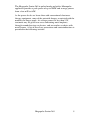
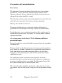
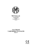
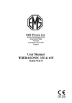
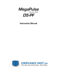
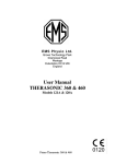
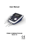
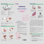
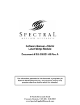
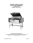
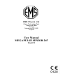
E M S P h ys i o L td
Grove Technology Park
Downsview Road
Wantage
Oxfordshire OX12 9FE
England
User Manual
MEGAPULSE SENIOR 265
Model 92
2
Megapulse Senior 265
General Information
This manual provides the necessary information for the installation
and operation of the Megapulse Senior 265.
These instructions must be studied before putting the unit into
operation.
The information contained in this manual is subject to change
without notice.
No part of this manual may be photocopied, reproduced or translated
into another language without the prior written consent of EMS
Physio Ltd.
The Megapulse 265 is continuous and pulsed shortwave therapy unit.
Shortwave therapy been applied to a wide range of conditions with
successful outcomes. These include acute and subacute traumatic
and inflammatory conditions, chronic rheumatoid and arthritic
conditions, resolution of haematomas and for pain relief. .
It is intended that the Megapulse Senior 265 is only used by qualified
healthcare professionals such as physiotherapists who have received
training in electrotherapy.
Record of Amendments
ISSUE
2
3
4
5
6
7
8
COMMENTS
DATE
Initial Issue
08/12/2006
Revised
01/10/2007
Revised
17/11/2008
Trouble shooting guide and
22/03/2010
EMC tables added
Revised
28/09/2010
Note about use of Flexipulse
20/07/2011
electrode added.
Declaration of conformity amended 06/10/2011
Megapulse Senior 265
3
EC Declaration of Conformity
EMS Physio Ltd
Grove Technology Park
Downsview Road
Wantage
Oxfordshire
OX12 9FE
United Kingdom
Declares that the following medical device is in conformity
with the essential requirements and provisions of Council
Directive 93/42/EEC and is subject to the procedure set out
in Annex 2 of Directive 93/42/EEC under the supervision of
Notified Body Number 0120, SGS United Kingdom Ltd.
Class IIb according to Annex IX of 93/42/EEC
Product Name
Megapulse Senior 265
Model Number
92
Signature
4
Position
Quality Assurance Manager
Date
6 October 2011
Date first issued
8 December 2006
th
Megapulse Senior 265
Contents
page
1
Title
General Information
3
Record of Amendments
3
Declaration of Conformity to 93/42/EEC
4
Contents
5
Warranty
6
Introduction
7
Precautions & Contraindications
10
Technical Specification
12
Controls and Markings
15
Installation
19
Operating Instructions
20
Maintenance
26
Trouble shooting
27
EMC Tables
28
Megapulse Senior 265
5
Warranty
This EMS Physio Ltd., (hereinafter called the company) product is
warranted against defects in materials and workmanship for a period
of two years from the date of shipment. The Company will at its
option, repair or replace components which prove to be defective
during the warranty period, provided that the repairs or replacements
are carried out by the Company or its approved agents.
The Company will consider itself responsible for the effects on
safety, reliability and performance of the product:only if assembly operations, re-adjustments, modifications or
repairs are carried out by persons authorised by it,
only if the product is used in accordance with the instructions
for use,
only if the electrical installation of the relevant room complies
with the appropriate national requirements.
Should the product be returned to the Company for repair it must be
sent carriage paid.
Consumable items, for example, electrodes, electrode covers and
batteries, are excluded from the above warranty.
6
Megapulse Senior 265
Introduction
Shortwave Therapy
Shortwave refers to electromagnetic radiation in the frequency range
2 to 100 MHz. Shortwave therapy is the application of
electromagnetic energy to the body at shortwave frequencies. At
these frequencies the electromagnetic energy is converted to thermal
energy by the induction of circulating currents in the tissue and
dielectric absorbtion in insulating tissue. Shortwave therapy units
may produce output power levels of up to 500W providing
significant heating to the area of the body being treated. For this
reason the treatment is often called shortwave diathermy (through
heating). To avoid equipment such as shortwave therapy units
interfering with radio communications, certain frequency ranges are
designated by international agreement as ISM (Industrial, Scientific
and Medical) bands. These are shown in the following table:Centre Frequency
MHz
6.78
13.560
27.120
40.680
433.92
915
2450
5800
24125
61250
122500
245000
Frequency Range
MHz
6.765-6.795
13.553-13-567
26.957-27.283
40.66-40.70
433.05-434.79
902-928
2400-2500
5725-5875
24000-24250
61000-61500
122000-123000
244000-246000
Maximum
Radiation Limit
Under Consideration
Unrestricted
Unrestricted
Unrestricted
Under Consideration
Unrestricted
Unrestricted
Unrestricted
Unrestricted
Under Consideration
Under Consideration
Under Consideration
Shortwave therapy equipment normally uses the band centred on
27.12 MHz. This corresponds to a wavelength, in a vacuum, of
approximately 11 metres.
Shortwave therapy is normally applied at a level which produces
detectable heating and the benefits are those associated with the
heating effect - encouragement of healing, pain relief, reduction of
muscle spasm, increase in mobility etc.
The difference between shortwave therapy and other methods of
heating is that it provides “deep heat”. Other heating techniques such
Megapulse Senior 265
7
as infrared therapy, hot-packs etc., provide the heat externally
whereas shortwave therapy generates heat within the tissue.
As with any electrotherapy, there are several potential dangers
associated with shortwave therapy. Since relatively high powers are
used, there is the possibility of producing burns if the patient is
unaware of the heat due to reduced thermal sensation, or if the
patient does not know what to expect during treatment. Metal in
treatment area will provide low impedance paths to the induced radio
frequency current, producing local heating and the possibility of
burning. In particular, treatment should never be given in the area of
metal implants, metal jewellery, buckles etc must be removed and
treatment must never be given with the patient on metal framed
couches or chairs. Patients with implanted electronic devices such as
cardiac pacemakers must not be treated. Other equipment, including
patient connected devices, may be adversely affected when in close
proximity to shortwave therapy equipment.
Pulsed Shortwave Therapy
Conventional shortwave therapy equipment described above,
produces a continuous wave output at 27.12 MHz. Pulsed shortwave
therapy equipment delivers the energy in pulses or bursts of
shortwave energy. The pulses are typically 20 to 400 microseconds
in duration (pulse width) and are repeated with a frequency of 5 to
800 Hz (pulse frequency). As with other modalities such as
ultrasound, it is found that delivering the energy in pulses is often
therapeutically more beneficial that providing the same amount of
energy in continuous wave form. Pulsed shortwave therapy appears
to be effective for many conditions especially in the early stages of
recovery.
Because the output is pulsed, the average output power levels can be
very low (less than 1W) and still produce effective treatment.
8
Megapulse Senior 265
The Megapulse Senior 265 in pulsed mode and with a Monopulse
applicator provides a peak power of up to 200W and average powers
from a few mW to 64W.
As the power levels are lower than with conventional shortwave
therapy equipment, some of the potential dangers associated with the
modality no longer apply. At average powers of less than 5 W,
treatment may be given over areas containing metal implants,
through wound dressings or plasters, and on couches or chairs with
metal frames. A list of necessary precautions and contraindications is
provided in the following sections.
Megapulse Senior 265
9
Precautions & Contraindications
Precautions
The function of certain implanted electrical devices, for example
pacemakers, may be adversely affected during treatment with
shortwave therapy. In case of doubt, the advice of the physician in
charge of the patient should be sought.
The function of other patient connected equipment may be adversely
affected by the operation of shortwave therapy equipment.
Hearing aids should be removed.
Treatment should not be given through clothing although it is
permissible to treat through a dressing or plaster in pulsed modes.
In pulsed modes areas containing internal metallic implants may be
treated at low power levels (less than 5 W average power) without
special precautions.
At average power levels above 5 W the following additional
precautions apply:
External conductive material should be removed from the immediate
treatment area.
Patients should not be allowed to come into contact with conductive
parts which are earthed or which have an appreciable capacitance to
earth and which may provide unwanted pathways for the radiofrequency current. In particular, beds or chairs with metal frames
should not be used.
The connecting cables associated with electrodes should be
positioned in such away that contact with the patient or conductive
or energy absorbing objects is avoided. The Megapulse Senior 265
has cable retaining clips on both electrode arms.
The electrode cables should be positioned so that they do not come
into contact with the body work or top panel of the equipment during
use.
10
Megapulse Senior 265
The electrode cables and plugs may get hot when used at high output
levels for prolonged periods. Allow to cool after treatment before
disconnecting.
Contraindications
Tumours, due to the risk of increased growth or metastatic activity.
Pregnancy, do not treat the lower abdomen, back or pelvis.
Menstruation, do not treat lower back or abdomen due to risk of
increased bleeding or pain.
Cardiac conditions, do not treat the chest area or near the cervical
ganglion.
Cardiac pacemakers, especially demand type, or any other
implanted electronic device.
Patients with reduced thermal sensitivity in the proposed
treatment area should not be treated with shortwave therapy.
Megapulse Senior 265
11
Technical Specification
General
Power Input
Classification (EN60601-1)
Mains Fuses
Size (height x width x depth)
Weight
Treatment Programs
Shortwave
Frequency
Maximum Output Power
Modes
Pulse Frequency
Pulse Width
Tuning
Treatment Timer
100-240 Vac 50/60 Hz
Class 1, Type BF
2 x T10A (5 x 20 mm)
940 x 470 x 470 mm
38 kg (excluding electrodes)
10 user-defined set-ups
27.12 MHz
400 W in continuous mode
1000 W peak in pulsed modes
Continuous, 3 in 3, 2in 3 and 1 in 3
5 - 800 Hz
20 - 400 µs
Automatic
0 to 30 minutes
The Megapulse Senior 265 is designed to operate from any 50/60 Hz
single phase supply between 100 and 240 Vac capable of supplying
1 kVA. Connection is via an IEC socket at the rear of the unit.
All information on model, serial number, and month/year of
manufacture is located on the rear panel.
Each Megapulse Senior 265 is supplied with a detachable mains
cable, spare fuses, a pair of 100mm capacitive electrodes, treatment
chart, output tester and this manual.
The Megapulse Senior 265 has been designed to meet the
requirements of BS EN 60601-1:1990 (BS5724:Part 1:1989)
"Medical Electrical Equipment, Part 1:General requirements for
Safety", BS EN 601-2-3:1991 "Medical Electrical Equipment, Part
2.3 Particular requirements for the safety of shortwave therapy
equipment"
Pulsed Output Waveform
12
Megapulse Senior 265
The pulse width may be set to 20, 40, 65, 100, 200 or 400 µs.
The Period may be from 1.25 ms (800Hz) to 200 ms (5Hz)
The duty cycle (%) is given by:
Pulse Frequency (Hz) x Pulse Width (µs) / 10000
In 3 in 3 mode the output pulse train is continuous
In 2 in 3 mode the pulses are on for 2/3 second and off for 1/3
second during each second of treatment.
In 1 in 3 mode the pulses are on for 1/3 second and off for 2/3
second during each second of treatment.
Environmental Conditions for Transport and Storage
Temperature
-10 to +35 C
Relative Humidity
5 to 95%
Atmospheric Pressure
500 to 1060 hPa
Megapulse Senior 265
13
Accessories
For continued safety, only electrodes and cables supplied by EMS
Physio Ltd. should be used with the Megapulse Senior 265.
Catalogue
Number
SLA990
SLA991
SLA992
SLA993
SLA996
SLA9960
SLA997
SLA9970
Description
Monopulse applicator
Flexipulse applicator
Pair of 100mm capacitive electrodes
Pair of 50mm capacitive electrodes
Pair rubber electrodes,180x120mm, with felt spacers
4 felt spacers for SLA996
Pair rubber electrodes,260x180mm, with felt spacers
4 felt spacers for SLA997
Supplied with each unit is a detachable mains lead complete suitable
for the country to which it is delivered. Replacement or additional
mains leads are shown below.
EMS Part Number
6-85
6-112
6-119
Description
UK mains lead
European mains lead
North America mains lead
For other countries contact EMS Physio Ltd. or the agent from
whom the unit was purchased.
Environmental
At the end its life, the Megapulse Senior 265 should not be disposed
of as unsorted general waste. Advice on appropriate disposal is
available from EMS Physio Ltd.
14
Megapulse Senior 265
Controls and Markings
Megapulse Senior 265 control panel
LCD
up and down
keys
IEC symbol
848-01-26
variability in
steps
mains switch with IEC
symbols 878-01-01 (mains on)
and 878-01-02 (mains off)
power
indicator
Megapulse Senior 265
menu key
control knob
15
Megapulse Senior 265 rear view
BNC connector for
Monopulse applicator
output sockets
for electrodes
rear panel
label
mains inlet
fuse label
16
Megapulse Senior 265
Rear Panel Label
model number
and
classification
IEC symbol
878-02-03
type BF
equipment
name and
address of
manufacturer
IEC symbol
878-03-04
non-ionising
radiation
IEC symbol 348
Attention, consult
accompanying documents
serial number
and date of
manufacture
CE mark
showing
conformity to
93/42/EEC
Fuse Label
The fuse label indicates the type and rating of the mains fuses.
Megapulse Senior 265
17
Monopulse Applicator
treatment
light
label
Monopulse Label
serial number and
date of manufacture
IEC symbol
878-03-04
non-ionising
radiation
18
Megapulse Senior 265
IEC symbol
878-03-01
dangerous
voltage
Installation
Upon receipt, check for any visible damage which may have
occurred in transit. If any signs of damage are found then retain all
packing material and inform the carrier and the Company or its agent
from whom the unit was purchased.
If not already fitted, connect a suitable plug to the mains cable. The
plug must have provision for an EARTH (GROUND) connection.
The mains cable has the following colour code: BROWN is LIVE
(LINE), BLUE is NEUTRAL and GREEN/YELLOW is EARTH.
The Megapulse Senior 265 unit must only be connected to a mains
supply with a protective earth conductor. If the integrity of the earth
connection is in doubt, do not connect the unit to the mains supply
Megapulse Senior 265
19
Operating Instructions
Power on sequence and general information
Connect the mains cable to the IEC socket on the rear of the unit and
to a suitable power outlet. Switch on the unit using the mains switch
on the control panel. The power indicator will light and the LCD will
show the EMS company logo and name, the model name and
number and the firmware version.
After approximately a further 3 seconds, the unit will give a short
beep and LCD will show the main shortwave set-up screen
Standard key functions
Throughout the operation of the Megapulse Senior 265, the up and
down keys are used to select the parameter highlighted.
20
Megapulse Senior 265
The rotary control is used to increase and decrease the highlighted
parameter.
The menu key is used to exit from the current screen or to select the
menu option highlighted.
Shortwave Set-up
Treatment Time: When the shortwave set-up screen is first displayed
the clock symbol is highlighted and the prompt at the bottom of the
screen shows the range of treatment time that may be set. With the
clock symbol highlighted, turn the rotary control clockwise to
increase the time and anticlockwise to decrease the time. The
treatment time can be set in 30s intervals.
Mode: The Megapulse Senior 265 can provide both continuous wave
and pulsed shortwave therapy. In addition, the unit has 3 pulsed
modes, 1in 3, 2 in 3, and 3 in 3. When the mode label is highlighted,
the available options are shown at the bottom of the screen. Select
the required mode using the rotary control. When continuous mode
is selected, the pulse width and frequency options are not displayed.
Megapulse Senior 265
21
Pulse Width: In pulsed modes, when the pulse width label is
highlighted, the pulse width may be set to 20, 40, 65, 100, 200 or
400 µs using the rotary control.
Frequency: In pulsed modes the frequency may be set to 5, 10, 20,
30, 50, 80, 100, 200, 400, 600, or 800Hz.
Electrodes: The Megapulse Senior 265 may be used with a variety of
electrodes. The Monopulse applicator is only suitable for pulsed
treatments and is, therefore, not available for selection in continuous
mode. All other electrodes may be used in continuous or pulsed
mode but it is recommended that the Monopulse applicator is used
for pulsed treatments whenever possible in order to minimise
electromagnetic interference with other equipment. By selecting the
electrode type with this option, the Megapulse Senior 265 limits the
output power to a level that can safely be delivered with the
electrode type chosen.
In the top right of the LCD the maximum peak and average power
for the current set-up is displayed. These values change as the mode,
pulse width, frequency and electrode type are changed. In addition a
graphical representation of the selected mode is shown.
It is recommended that the unit is left switched on for 15 minutes
after treatment has ended to allow the fan to continue to operate and
cool the unit.
Treatment using the Monopulse applicator
Attach the Monopulse applicator to one of the electrode arms and
lock it into place by tightening the sleeve at the end of the arm
Connect one end of the BNC cable supplied to the socket on the rear
of the applicator and the other end to the BNC socket on the rear of
the unit.
Slacken the arm handwheels and position the applicator over the
treatment site so that the rim around the rim of the applicator is about
1 cm from the patient. Tighten the handwheels to prevent movement.
Make sure that Monopulse is selected for the electrode type. Use the
up and down keys to highlight the output symbol. To start treatment,
turn the rotary control clockwise.
If the treatment time is zero, or the Monopulse applicator is not
connected, the unit will give a short alarm to indicate that the output
cannot be energised.
Megapulse Senior 265
22
If the treatment time is not zero, the output of the Megapulse will be
energised, the output symbol will flash and the treatment time will
begin to count down, Treatment will be displayed at the bottom of
the screen and the treatment light on the rear of the Monopulse
applicator will light. Advance the output control to the required
level.
The output level is shown as a percentage of the maximum power
available with the current set-up. In the example shown above, the
output level is set to 75% of 200W peak and 7.8 average, giving an
output of 150W peak and 5.85W average.
When the treatment time reaches zero, the pulsed shortwave energy
from the monopulse applicator is terminated, the light of the rear of
the applicator will turn off, the output display will show 0% and a
three second alarm is sounded.
The monopulse applicator is fitted with a cooling fan. The fan
operates only at high average output power levels.
Megapulse Senior 265
23
Treatment using rigid capacitive electrodes
Attach the 5 cm or 10 cm capacitive electrodes to the arms and
secure in place by tightening the retaining sleeve. Connect the
electrode plugs to the output sockets on the Megapulse Senior 265
rear panel. Ensure that the electrode cables are kept apart from each
other using the cable retaining clips on the electrode arms.
Position the electrodes using the Megapulse arms so that the radiofrequency electric field from the electrodes will pass through the
treatment site. Tighten the handwheels to prevent movement.
Make sure that the electrode type selected is the same as those being
used. Use the up and down keys to highlight the output symbol. To
start treatment, turn the rotary control clockwise.
If the treatment time is zero, the unit will give a short alarm to
indicate that the output cannot be energised.
If the treatment time is not zero, the output of the Megapulse will be
energised, the output symbol will flash and the treatment time will
begin to count down, Treatment will be displayed at the bottom of
the screen. Advance the output control to the required level; in
continuous mode this is normally when the patient can feel warmth
from the treatment. The presence of output from the electrodes may
be verified using the fluorescent output tester which will light when
placed near the electrodes.
The Megapulse Senior 265 has automatic tuning in order to optimise
power transfer to the patient. While the unit is tuning, the treatment
timer will not count down and the message, tuning, is shown on the
bottom line of the display. Should the unit be unable to tune to the
load provided by the electrodes, turn off the output power using the
rotary control, reposition the electrodes and try again.
In pulsed modes with frequencies less than 100 Hz, the Megapulse
Senior 265 will output pulsed energy at 100 Hz until the unit has
tuned.
When the treatment time reaches zero, the shortwave energy from
the electrodes is terminated, the output display will show 0% and a
three second alarm is sounded.
24
Megapulse Senior 265
Treatment using flexible rubber capacitive electrodes
Connect the rubber electrode plugs to the output sockets on the
Megapulse Senior 265 rear panel. Place the flexible electrodes in
position using the felt spacers provided between the skin and the
electrode. The electrode spacing is controlled by the number of felt
spacers used.
When using rubber pad electrodes it is recommended that the
electrode cables are held together using the velcro straps supplied.
This allows the unit to tune over a wider range of electrode
configurations (this is also recommended when using the Flexipulse
electrode assembly).
The operating procedure is the same as that for the rigid capacitive
electrodes.
Megapulse Senior 265
25
Maintenance
The Megapulse Senior 265 and monopulse applicator may be
cleaned by wiping over with a damp cloth. The use of abrasive
materials and cleaning solvents should be avoided.
Regularly (at least monthly) inspect electrode leads, cables and
connectors for signs of damage.
The unit calibration should be checked at least annually.
The mains fuses are located at the rear of the unit in a compartment
below the mains inlet. The compartment cannot be opened unless the
mains lead is removed from the IEC socket. Information on fuse type
and rating is given on the label adjacent to the mains inlet and in the
Technical Specification section of this manual.
If the mains fuses continue to blow then EMS Physio qualified
Service personnel must be called in.
There are no user serviceable parts inside the unit and it should
not be opened.
Full servicing instructions are available on request.
26
Megapulse Senior 265
Trouble Shooting
Sympton
Unit shows “Tuning” and
“Treatment” will not begin.
Action
Check correct electrodes have
been selected.
Check electrodes are securely
connected.
Check electrode cables are
routed as described in relevant
section.
Ensure that metal framed beds,
tables and chairs are not in the
treatment area.
Check electrodes are positioned
directly opposite each other and
either side of the treatment area.
Unit shows “Treatment” but no
warmth can be felt by patient
and flourescent indicator does
not light.
Check correct electrodes have
been selected.
Check electrodes are securely
connected.
Check power output level is
greater than 10%.
Unit shows “Over temperature”
Leave unit switched on and
allow to cool for 15 minutes
before switching unit off and
then restarting unit.
If the actions above do not
resolve the problem please
contact the manufacturer or an
approved service agent for
further advise.
Megapulse Senior 265
27
1
2
3
5
6
7
8
28
Guidance and manufacturers declaration – electromagnetic emissions
The Megapulse Senior 265 is intended for use in the electromagnetic
environment specified below. The customer or the user of the 265 should
assure that it is used in such an environment.
Electromagnetic environment Emissions Test
Compliance
guidance
The Megapulse Senior 265 must emit
RF emissions
electromagnetic energy in order to
Group 2
perform its intended function. Nearby
CISPR 11
electronic equipment may be affected.
RF emissions
Class A
CISPR 11
Harmonic
The265 is suitable for use in all
Class A
emissions
establishments other than domestic and
IEC 6100-3-2
those directly connected to the public
low-voltage power supply network that
Voltage
supplies buildings used for domestic
fluctuations
purposes.
Complies
Flicker emissions
IEC 61000-3-3
Megapulse Senior 265
Guidance and manufacturers declaration – electromagnetic immunity
The Megapulse Senior 265 is intended for use in the electromagnetic
environment specified below. The customer or the user of the 265 should
assure that it is used in such an environment.
Electromagnetic
IEC 60601
Compliance
Immunity test
Environment
test level
level
guidance
Floors should be
wood, concrete or
Electrostatic
±6 kV
ceramic tile. If floors
±6 kV contact
discharge
contact
are covered with
(ESD)
synthetic material,
±8 kV air
±8 kV air
the relative humidity
IEC 61000-4-2
should be at least
30%.
±2 kV for
Mains power quality
power supply ±2 kV for power
Electrical fast
should be that of a
supply lines
lines
transient/burst
typical commercial or
±1 kV for
±1 kV for
hospital
IEC61000-4-4
input/output lines
input/output
environment.
lines
±1 kV
Mains power quality
differential
±1 kV differential
Surge
should be that of a
mode
mode
typical commercial or
±2 kV common
±2 kV
IEC61000-4-5
hospital
mode
common
environment.
mode
<5% UT
(>95% dip in
Mains power quality
UT)
should be that of a
<5% UT
For 0,5 cycle
typical commercial or
(>95% dip in UT)
Voltage dips,
40% UT
For 0,5 cycle
hospital
short
(60% dip in
environment. If the
40%
UT
interruptions
UT)
user of the 265
(60%
dip
in
UT)
and voltage
For 5 cycles
requires continued
For 5 cycles
variations on
operation during
70% UT
power supply
70% UT
power mains
(30%
dip
in
input lines
(30% dip in UT)
interruptions, it is
UT)
For 25 cycles
recommended that
For 25
IEC 61000-4<5% UT
the 265 be powered
cycles
11
(>95% dip in UT)
from an
<5% UT
For 5 sec
uninterruptible power
(>95% dip in
supply.
UT)
For 5 sec
Power frequency
magnetic field should
Power
be at levels
frequency
characteristic of a
(50/60 Hz)
3 A/m
3 A/m
typical location in a
Magnetic field
typical commercial or
IEC 61000-4-8
hospital
environment.
NOTE UT is the a.c. mains voltage prior to application of the test level.
Megapulse Senior 265
29
Guidance and manufacturers declaration – Electromagnetic immunity.
The Megapulse Senior 265 is intended for use in the electromagnetic environment specified
below. The customer or user of the Megapulse Senior 265 should assure that it is used in such
an environment.
Immunity
Test
IEC 60601
Test level
Compliance
level
Electromagnetic Environment
Guidance
Portable and mobile RF communications
equipment should be used no closer to any part
of the Megapulse Senior 265, including cables,
than the recommended separation distance
calculated from the equation applicable to the
frequency of the transmitter.
Recommended separation distance
Conducted RF
IEC61000-4-6
3Vrms
150kHz to
80MHz
3V
Radiated RF
IEC61000-4-3
3V/m
3V/m
80MHz to
2.5GHz
d=3.5√P/V1
d=3.5√P/E1 80MHz to 800MHz
d=7√P/E1 800MHz to 2.5GHz
where P is the maximum output power rating of
the transmitter according to the manufacturer
and d is the recommended separation distance
in metres (m).
Field strengths from fixed RF transmitters, as
determined by an electromagnetic site surveya
should be less than the compliance level in each
frequency rangeb.
Interference may occur in the vicinity of
equipment marked with the following symbol:
NOTE 1 At 80MHz and 800MHz the higher frequency range applies.
NOTE 2 These guidelines may not apply in all situations. Electromagnetic propagation is
affected by absorption and reflection from structures, objects and people.
a
Field strengths from fixed transmitters, such as base stations for radio (cellular/cordless)
telephones and land mobile radios, amateur radio, AM and FM radio broadcast and TV
broadcast cannot be predicted theoretically with accuracy. To assess the electromagnetic
environment due to fixed RF transmitters, an electromagnetic site survey should be considered.
If the measured field strength in the location in which the Megapulse Senior 265 is used
exceeds the applicable RF compliance level above, the Megapulse Senior 265 should be
observed to verify normal operation. If abnormal performance is observed additional measures
may be necessary, such as re-orienting or relocating the Megapulse Senior 265.
b
Over the frequency range 10kHz to 80Mhz, field strengths should be less than 3 V/m.
Recommended separation distances between portable and mobile RF
communications equipment and the Megapulse Senior 265
The Megapulse Senior 265 is intended for use in an electromagnetic environment in which
radiated RF disturbances are controlled. The customer or user of the 265 can help prevent
electromagnetic interference by maintaining a minimum distance between portable and
mobile RF communications equipment (transmitters) and the Megapulse Senior 265 as
recommended below, according to the maximum output power of the communications
equipment.
150kHz to 80MHz
d=3.5√P/V1
80MHz to 800MHz
d=3.5√P/E1
800MHz to 2.5GHz
d=7√P/E1
0.01
0.12
0.12
0.23
0.1
0.38
0.38
0.73
1
1.2
1.2
2.3
10
3.8
3.8
7.3
100
12
12
23
For transmitters rated at a maximum output power not listed above, the recommended
separation distance d in meters (m) can be estimated using the equation applicable to the
frequency of the transmitter, where P is the maximum output power rating in watts (W)
according to the transmitter manufacturer.
NOTE 1 At 80MHz and 800MHz the separation distance for the higher frequency range
applies.
NOTE 2 These guidelines may not apply in all situations. Electromagnetic propagation is
affected by absorption and reflection from structures, objects and people.
Megapulse Senior 265
31
Essential Performance
Power Input
Output Frequency
Maximum Output Power
(into 50 ohms)
Modes
Pulse Frequency
Pulse Width
Treatment Timer
32
100-240 Vac 50/60 Hz
27.12 MHz (± 120 kHz)
400 W (± 30%) in continuous mode
1000 W peak (± 30%) in pulsed modes
Continuous, 3 in 3, 2in 3 and 1 in 3
5,10, 20, 30, 50, 80, 100, 200, 400, 600,
800 Hz (± 10%)
20, 40, 65, 100, 200, 400 µs (± 10%)
0 to 30 minutes
Megapulse Senior 265