1
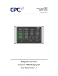
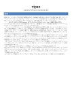
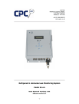
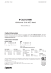
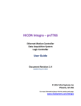
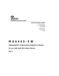
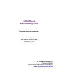
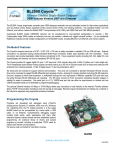
Unit 7/8,
Heathrow Causeway Estate,
Ariel Way, Hounslow
Middlesex, TW4 6JW
+44 (0) 208 6302270
www.cpcuk.co.uk
Digital Signal Monitoring System
Model IMEC16I
User Manual Version 1.00
Software version 1.1
-1-
All rights reserved
The information contained in this manual has been carefully checked and is believed to be
accurate. However, CPC (UK) assumes no responsibility for any inaccuracies that may be
contained herein. In no event will CPC (UK), be liable for any direct, indirect, special,
incidental, or consequential damages resulting from any defect or omission in this manual,
even if advised of the possibility of such damages. In the interest of continued product
development, CPC (UK) reserves the right to make improvements to this manual, and the
products described herein, at any time without notice or obligation.
Copyright
Copyright by CPC (UK). No part of this manual may be reproduced or transmitted in any
Form without express written authorization from CPC (UK).
Trademarks
All trademarks are acknowledged and are the property of their respective holders.
-2-
Contents
1. Introduction ............................................................................................................. 4
2. Unit Hardware .......................................................................................................... 5
2.1 Power Input Connector (J7) ................................................................................. 5
2.2 Digital Input Connectors 1 – 16 (J3, J4, J5 and J6) ................................................. 6
2.3 Ethernet Connector ............................................................................................. 7
2.4 Battery Link........................................................................................................ 7
2.5 Factory Reset Link............................................................................................... 8
3. Web Browser Interface.............................................................................................. 9
3.2 Status Overview.................................................................................................. 9
3.3 Configuration page ............................................................................................ 10
3.3.1 Unit Settings .............................................................................................. 11
3.3.2 Channel Settings ........................................................................................ 12
4. XML Interface......................................................................................................... 13
5. Specification........................................................................................................... 14
6. Revision history ...................................................................................................... 15
-3-
1. Introduction
The IMEC16I is a versatile, fully configurable unit for monitoring digital input signals such as,
fault switches, alarm relays, position switches and level switches. The unit includes an
Ethernet 10BaseT interface, enabling the unit to be connected to a TCP-IP based network.
Information from the unit can be viewed using a standard web-browser, configuration of the
unit is also achieved using a standard web-browser. A simple XML interface enables thirdparty alarm and management servers to collect status information unit.
The unit is supplied in PCB only format, but sometimes maybe supplied within enclosures
containing other equipment (such as routers, power supplies and signal conditioning devices),
this manual explains the features of the PCB only.
-4-
2. Unit Hardware
The IMEC16I includes the following hardware features,
Power Input Connector
Digital Input Connectors 1 – 16
Ethernet Connector
Battery Link
Factory Reset Link
Battery Link
Inputs 9 - 16
INP9
UTP
BAT
RCM3000
Core module
PWR
Ethernet
INP10 INP11 INP12 INP13 INP14 INP15 INP16
Power In
76mm
RESET
INP1
INP2
INP3
Factory Reset
INP4
INP5
INP6
INP7
INP8
Inputs 1 - 8
133mm
Figure 2.0 Layout
2.1 Power Input Connector (J7)
The power input connector (J7) is used to provide power to the unit. The unit requires a
12VDC power supply, and should be connected as shown,
Figure 2.1 Power connections
Note: The unit includes reverse polarity protection, in case the user incorrectly connects the
power supply.
-5-
2.2 Digital Input Connectors 1 – 16 (J3, J4, J5 and J6)
The unit includes 16 digital inputs which are used for monitoring digital input signals in the
form of “volt-free” contacts. Without any connection to the input, the input is in-active
(false). If the input is connected to the +12VDC supply, the input is active (true).
Each input includes an LED which indicates the status of the input,
Input in-active (false)
Input active (true)
= LED not illuminated
= LED illuminated
Each input connector provides a common connection (connected via the PCB to the +12VDC
supply connection) and an input signal connection,
BAT
RESET
Figure 2.2 Digital Input Connections
Input signals should be connected as shown,
Fig 2.3 Digital Input Examples
Note: If your application requires monitoring of other types of digital signals (such as
240VAC signals), external signal conditioning is required. Contact CPC (UK) for more details.
-6-
2.3 Ethernet Connector
The unit includes a 10BaseT Ethernet network interface; an RG45 connector (located on the
CPU core module) enables connection of the unit to a network. In a typical application the
unit will be connected to a network hub, switch or router using a standard CAT5 patch cable.
The unit may also be connected directly to a PC or Laptop using a CAT5 cross-over cable.
Note: The maximum cable length between the IMEC16I and other devices should be no
more the 80m.
The CPU core module also incorporates LED’s which shows the status of the Ethernet network
connection,
Link LED = Illuminated when network connected
ACT LED = Flickers with network activity
Fig 2.4 Ethernet Interface
2.4 Battery Link
There is an onboard battery located underneath the CPU core module, link JP2 enables and
disables the battery. During normal operation the link must be permanently fitted. However,
if the unit it be stored for long periods of time it is recommended that the link is removed to
pro-long battery life.
Fig 2.5 Battery Link (JP2)
-7-
2.5 Factory Reset Link
The factory reset link (JP1) enables the user to reload the factory default software
configuration. To reload defaults,
1.
2.
3.
4.
5.
6.
Power off the unit
Fit the factory link
Power up the unit
Wait 5 seconds
Remove the link
Factory default software configuration will now be loaded
RESET
Normal
Load
(Default) Defaults
Fig 2.6 Factory reset link (JP1)
-8-
3. Web Browser Interface
The user may view input status and configure the unit using the HTML web-browser
interface.
3.1 Connecting to the unit
To connect to a new unit, enter the default IP address in your web-browser address bar,
Default IP Address = 192.168.1.103
Note: To avoid any IP address conflicts, it is recommended that before the desired IP
address settings have been set, that you connect directly to the unit using a CAT5 cross-over
lead.
Note: When connecting to the unit directly using a CAT5 cross-over cable it maybe necessary
to change your PC’s IP address settings.
3.2 Status Overview
Once connected to the unit the status overview page will be displayed,
Fig 3.0 Status overview page
The status overview page displays the current status of all the unit digital inputs, the unit
name and the current IP address setting.
The toolbar at the top of the page enables includes an “Overview” link which reloads the
status overview page, and a “Setup” link which prompts the user to enter a username and
password – before displaying the unit configuration page.
The status overview page will automatically refresh once every 15 seconds.
-9-
3.3 Configuration page
The configuration page enables the user to setup software variables within the unit. The unit
is designed to be completely user configurable, allowing the user to rename each input, the
input states, unit name etc..
When accessing the configuration page, the user will be prompted to enter the administrator
user name and password,
Default username = admin
Default password = password
Fig 3.1 Password prompt
Note: The password prompt screen may vary, depending on the web-browser you are using.
If an invalid username or password has been entered, the user will be prompted again to
enter the username and password. If a valid username and password has been entered, the
configuration page will be displayed,
Fig 3.2 Configuration page
The configuration page is divided into two sections, “Unit Settings” and “Channel Settings” (it
maybe necessary to scroll down the page to view all the “Channel Settings”).
- 10 -
3.3.1 Unit Settings
The unit settings section of the configuration page allows the user to setup the network
settings, change the administer password etc,
Fig 3.3 Unit Settings
Note: When changing any of the unit settings, the “Change Unit Settings” button must be
clicked, before the new settings will take effect.
Software Version –
Read only, displays the current software version of the unit.
IP Address –
The IP address of the unit. If you change this setting the current
connection to the unit will be lost.
Default = 255.255.255.0, min 0 max 255 per segment.
Subnet mask –
The subnet mask. If you change this setting the current connection
to the unit maybe lost.
Default = 192.168.0.103, min 0 max 255 per segment.
Default Gateway –
The default gateway IP address, normally left as 0.0.0.0
Default = 0.0.0.0, min 0 max 255 per segment.
DNS Server –
The DNS servers IP address, only set if you are using a DNS server
within you network.
Default = 0.0.0.0, min 0 max 255 per segment.
System password -
The administrator password.
Default = password, max 20 characters (alpha numerical only)
Unit Name -
The unit name, as displayed on the overview page, and within the
XML status report.
Default = IMEC 1, max 60 characters (alpha numerical only)
De-bounce period -
The digital input de-bounce period, the period in seconds that the
digital input must have changed state for before the unit recognises
the change.
Default 2s, min 0s max 30s
Reset all settings -
If ticked, the factory default settings will be reloaded (with the
exception of the IP address settings)
- 11 -
3.3.2 Channel Settings
The channel settings of the configuration page allows the user to setup each inputs name
and the states to be displayed when the input is in-active (false) or active (true),
Fig 3.4 Channel Settings
Note: When changing any of the unit settings, the “Change Channel Settings” button must
be clicked, before the new settings will take effect.
For each channel the following settings maybe changed,
Name -
The name of the digital input, as displayed on the overview page, and within
the XML status report.
Default = Digital Input #, max 20 characters (alpha numerical only)
True -
The state to be displayed when the input is active (true), as displayed on the
overview page, and within the XML status report.
Default = True, max 12 characters (alpha numerical only)
False -
The state to be displayed when the input is in-active (false), as displayed on
the overview page, and within the XML status report.
Default = False, max 12 characters (alpha numerical only)
- 12 -
4. XML Interface
The XML interface enables third party alarm servers and management systems to read status
information from the unit.
To read the XML status report, the following HTTP request must be sent,
HTTP://<IP Address>/xmlstatus.xml
The following XML status report will be returned,
<Status>
<UnitType>CPC UK - IMEC 16I</UnitType>
<UnitName>IMEC 1</UnitName>
<Report>
<Input ID="1" name="Digital Input 1" value="FALSE" />
<Input ID="2" name="Digital Input 2" value="FALSE" />
<Input ID="3" name="Digital Input 3" value="FALSE" />
<Input ID="4" name="Digital Input 4" value="FALSE" />
<Input ID="5" name="Digital Input 5" value="FALSE" />
<Input ID="6" name="Digital Input 6" value="FALSE" />
<Input ID="7" name="Digital Input 7" value="FALSE" />
<Input ID="8" name="Digital Input 8" value="FALSE" />
<Input ID="9" name="Digital Input 9" value="FALSE" />
<Input ID="10" name="Digital Input 10" value="FALSE" />
<Input ID="11" name="Digital Input 11" value="FALSE" />
<Input ID="12" name="Digital Input 12" value="FALSE" />
<Input ID="13" name="Digital Input 13" value="FALSE" />
<Input ID="14" name="Digital Input 14" value="FALSE" />
<Input ID="15" name="Digital Input 15" value="FALSE" />
<Input ID="16" name="Digital Input 16" value="FALSE" />
</Report>
</Status>
<UnitType>
will always contain “CPC UK – IMEC 16I”.
<UnitName>
will contain the unit name as configured by the user.
<Input ID=
will always show the relevant digital input channel number.
<name=
will show the digital input channel name as configured by the user.
<value=
will show the current digital input state, as configured by the user.
Note: An additional XML report is available which also displays the state of the factory reset
input, for testing purposes only, HTTP://<IP Address>/xmlteststatus.xml
- 13 -
5. Specification
Dimensions
133 x 76 x 25 mm
Power Supply
12VDC > 250mA
Digital Inputs
16 off, 12VDC (supply voltage) sensing
1 off, factory reset link
Interfaces
HTTP
XML
Communications
Ethernet 10BaseT
Operating Environment
32º F to 115º F (0º C to 47º C)
0 to 95% Relative Humidity (non-condensing)
- 14 -
6. Revision history
1.0 First draft of document
01/11/2007
- 15 -