1
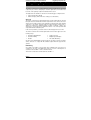
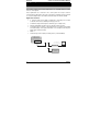
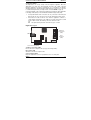
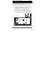
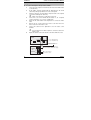
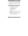
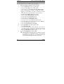
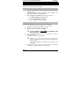
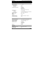
Installation Manual
Premier Com300/Com2400
Issue 4
Contents
Com300 & Com2400 Installation Manual
Contents
1. Regulatory Requirements ................................................................. 3
General............................................................................................................... 3
Approval ....................................................................................................... 3
REN Rating ................................................................................................... 3
2. Overview ............................................................................................ 4
General............................................................................................................... 4
Digimodem Features.................................................................................... 4
Connection Status........................................................................................ 5
Digimodem Layout ....................................................................................... 5
Operation ........................................................................................................... 6
Communicator Operation ............................................................................ 6
Modem Operation ........................................................................................ 6
3. Installation ......................................................................................... 7
Plugging on the Digimodem ............................................................................. 7
Telephone Line Connections............................................................................ 8
Setting up the Com Ports.................................................................................. 9
Programming the Com300 and Com2400...................................................... 10
What will be sent as a Text Message ............................................................. 11
Testing the communicator .............................................................................. 12
4. Using Com2400 with old Premier ................................................... 13
Installation ....................................................................................................... 13
Using a PC for local Upload/Download.......................................................... 13
5. Specifications .................................................................................. 14
Electrical .......................................................................................................... 14
Environmental.................................................................................................. 14
Physical............................................................................................................ 14
Standards......................................................................................................... 15
Warranty........................................................................................................... 15
2
INS175
Com300 & Com2400 Installation Manual
Regulatory Requirements
1. Regulatory Requirements
General
The Premier Com300 and Com2400 digimodem must be installed by an electrically
competent person. Before attempting to install the digimodems, the installer must
be aware of the regulatory requirements detailed in this section.
The digimodems are suitable for connection to the following types of telephone line:
•
Direct exchange lines (PSTN)
•
PABX exchanges (with or without secondary proceed indication)
Approval
The Premier Com300 and Com2400 digimodems are both manufactured to meet all
European Area telecommunication network requirements. These devices have been
approved for use with Council Decision 98/482/EC for pan-European single terminal
connection to the public switched telephone network (PSTN). However due to
differences between the individual PSTNs provided in different countries, the
approval does not in itself give unconditional assurance of successful operation with
every PSTN network termination point.
In the event of problems, you should contact Technical Support at Texecom Ltd.
The Premier Com300 and Com2400 digimodems have both been approved for the
following usage:
•
Automatic Call Initialisation
•
Serial Connection
•
Automatic Dialling
•
Multiple Repeat Attempts
•
Modem
•
Line Status Monitoring
Any other usage will invalidate any approval given to the devices and as a result the
devices will cease to comply with the standards against which the approval was
granted.
REN Rating
As a guide to the number of devices that can be simultaneously connected to an
exclusive line, the sum of the REN values must not exceed 4. A BT telephone is
assumed to have an REN = 1 unless otherwise marked.
The Premier Com300 and Com2400 both have an REN = 1
INS175
3
Overview
Com300 & Com2400 Installation Manual
2. Overview
General
The Premier Com300 and Com2400 digimodems are compatible with the Premier
series of control panels:
These digimodems are connected to the control panel via an 8-pin connector
located at the top right hand corner of the control panel. Terminals are also provided
to connect the digimodems to the Public Switched Telephone Network (PSTN).
Digimodem Features
•
8 channel multi format digital communicator supporting Fast Format,
Contact ID, SIA Level 2/3 and EasyCom Pager protocols
•
6 Alarm Receiving Centre telephone numbers (up to 24 digits each)
•
Fully programmable reporting codes (Contact ID & SIA Level only)
•
300-baud modem (Com300) or 2400-baud modem (Com2400) for uploading
and downloading control panel information over a telephone line using the
Wintex UDL software and a PC
•
REN = 1
•
Short Message Service (SMS) to mobile phones (Com2400 ONLY)
P re m ie r S e r ie s
C o n tro l P a n e l
P lug o n D ig im o d em
(C o m IS D N )
P C a n d M o d e m fo r
R e m o te U p lo a d /D o w nlo a d
M odem
A la rm R e c e iv in g
C e n tre
4
INS175
Com300 & Com2400 Installation Manual
Overview
Connection Status
The digimodems can accept serially connected telephone apparatus. When the
digimodems are online they will temporarily disconnect all serially connected
telephone apparatus (e.g. phones, answer-phone, etc.) so that they do not interfere
with data transmission. This means that the digimodems do not have to be connected
to a dedicated telephone line (see telephone line connection NOTES on page 12).
Connection terminals on the Com300 and Com2400 are described as either ‘Safety Extra
Low Voltage’ circuits (SELV) or ‘Telecommunications Network Voltage’ circuits (TNV).
•
It is important that the TNV connections are only connected to the PSTN, and
SELV circuits are only connected to other circuits designated as SELV circuits
•
Interconnection circuits should be such that the equipment continues to
comply with the requirements of 4.2 of EN 41003 for TNV circuits and 2.3 of EN
60950 for SELV circuits, after making connections between circuits
The digimodem layout below shows the two types of circuits.
Digimodem Layout
T
R
Audio
T1
Telephone
Connections
(TNV)
R1
SELV
Com 1
RJ11
Connector
(TNV)
Connection Plug (SELV)
Telephone Connections (TNV)
Direct connection for telephone line (see page 8 for wiring details).
RJ11 Socket (TNV)
Alternative connection for telephone line.
Connection Plug (SELV)
Plugs into digimodem socket on top right hand corner of control panel.
INS175
5
Overview
Com300 & Com2400 Installation Manual
Operation
The digimodems can be used to report system events to a Central Monitoring
Station (using Fast Format, Contact ID or SIA Level 2/3) or to upload/download
control panel information using the Wintex UDL software and a PC.
In order to use the digimodems for uploading and downloading control panel
information you will require a PC with Windows 95, 98 or NT and an analogue
modem that supports V.21, V.22 or V.22bis operation.
To obtain your copy of the Wintex UDL software, please complete and return the
Software Registration form enclosed with the Premier Com300 or Com2400.
Communicator Operation
When a reportable system event occurs, the digimodem will seize the telephone line
and dial the telephone number for the Alarm Receiving Centre, once the receiver
answers the call the following sequence of events will occur.
•
The digimodem will send a handshake signal
•
If the handshake signal is acknowledged, the digimodem will report the event
to the Alarm Receiving Centre using Fast Format, Contact ID or SIA Level 2/3
•
If the handshake signal is not acknowledged, the digimodem will shut
down and attempt to dial another telephone number.
Once the event has been successfully reported to the receiver, the receiver will
send back an acknowledgement signal and the digimodem will shut down. The
digimodem will then return to its normal mode
Modem Operation
The digimodem will monitor the telephone line for an incoming ringing signal, once
the ringing signal is detected the following sequence of events will occur.
•
The digimodem will pick up the telephone line and establish a connection with
the remote computer
•
Once the connection is established, the remote computer can be used to
upload data from the control panel or download data from a PC
•
Once the remote computer has finished uploading/downloading, it will tell the
digimodem to go hang up. The digimodem will then return to its normal mode
6
INS175
Com300 & Com2400 Installation Manual
Installation
3. Installation
Plugging on the Digimodem
³
To install the digimodem, proceed as follows:
If fitting to an old Premier panel (with an 8 pin header) refer to page 13.
1.
Isolate ALL power from the control panel (AC Mains and Battery). Do not
continue if there is power still present on the control panel.
2.
Installing the digimodem with power still present on the control panel will
seriously damage the digimodem and invalidate any warranty.
3.
Ensure that the board is the correct way up (see picture below).
4.
Locate the 10-pin plug on the digimodem into the digimodem socket on the
control panel and line up the mounting holes with the pillars in the base.
5.
Once all the holes line up, screw the digimodem into place.
On the Premier 24 Plastic panel, the digimodem locates onto pins.
T
R
T1
Audio
R1
Com 1
+ BATT
N/O COM N/C
OP5
A.C.
Box
Tamp
L/M
OP4+
Kick
Start
R/R
OP3+
DC+
OP2-
DC-
OP1-
5
Aux
Tamp
+12v
Bell Tamp
7
0v
Tx1 Rx1
Strb -
Load
Defaults
Jp9
Engineer
Remote
Expansion
Heartbeat
Tx2 Rx2
JP7
V
100mA =
1 Amp
+ -
T R
NETWORK 1
+ -
T R
NETWORK 2
+
Aux 12v
A
T
Zone 1
A
T
Zone 2
A
T
Zone 3
A
T
Zone 4
A
T
Zone 5
A
T
Zone 6
A
T
Zone 7
A
T
Zone 8
Bell/Strb - 1Amp
Aux 12v
1Amp
8
INS175
-
Com 1
4
6
Spk
Spk+
Com 2
3
Network 1
1Amp
DIGICOM OUTPUTS
2
Network 2
1Amp
1
7
Installation
Com300 & Com2400 Installation Manual
Telephone Line Connections
³
To connect the telephone line, proceed as follows:
1.
Connection to the telephone network must be made via an NTE5 master
socket (Line Box).
2.
Fit the rubber grommet supplied with the digimodem into the 20mm
cable entry in the top right hand corner of the control panel.
3.
Using the cable type 1/0.5mm CW1308, strip back 5mm of the required
cores and feed through the cable entry.
4.
Alarm or any other type of cable must not be used.
Connect the cores to the terminal blocks marked ‘T’, ‘R’. If required
connect serial devices to ‘T1’ & ‘R1’ on digimodem.
5.
Ensure the the eath terminal on the digimodem is connected to mains
earth.
6.
Remove the two screws from the BT master socket and remove the
bottom section from the master socket.
7.
Connect the cable from the digimodem to the BT master socket
terminals.
8.
A special insertion tool will be required to connect the cable to the
master socket.
Replace the bottom section of the master socket and re-fit the two screws.
Master
Socket
6
5
4
3
2
1
T = 5 or A - White/Blue ring
R = 2 or B - Blue/White ring
Telephone cable
Type 1/0.5mm CW1308
Com300 T
R
or
Com2400 T1
R1
8
This terminal must be connected to
the incoming AC Mains earth supply
To other telephone
extension sockets
INS175
Com300 & Com2400 Installation Manual
Installation
All apparatus that requires access to emergency services (999 and 112)
must be connected directly to the master socket. Devices that do not
require access to these services such as faxes, modems and answer
machines etc. can be connected to the extension sockets (see Note below).
Devices that are connected to the extension sockets will be isolated from
the telephone line whilst the Premier Com300 or Com2400 is active and
therefore access to the line (including emergency services) during this
period is not possible.
Setting up the Com Ports
³
To setup the Com Ports for the Com300 or Com2400, proceed as follows:
1.
2.
3.
4.
.
and press .
Select the Com Port Setup menu and press .
• Select Onboard Digicom and press • Select Com300 or Com2400 and press Enter into the Engineers Menu
Select the UDL/Digi Options menu
If fitting a Com2400 to a Premier 24 only.
• select Com1 and press
• Select Com2400 and press
5.
If a Com2400 is being used for SMS text messaging, ensure that the
SMS service centre number is programmed in Radio/SMS options(this is
normally 07860 980480 or 07785 499993 and does not normally need to
be changed.
6.
INS175
COM1 will not be available for use by any other device on the
Premier 24.
Calls to these numbers are charged at the normal rates for calls to
mobile phones from a standard telephone line.
To exit from the Com Port Setup menu press
.
9
Installation
Com300 & Com2400 Installation Manual
Programming the Com300 and Com2400
³
To program the Com300 or Com2400, proceed as follows:
.
and press .
Select the required ARC set , or 1.
Enter into the Engineers Menu
2.
Select the Program Digi menu
•
• Select the Protocol i.e. Fast format, Contact ID, SMS Messaging
• Enter the Primary Number for the ARC or 1st Mobile phone number
• Enter the Secondary Number for the ARC or 2nd Mobile phone number
SMS Text Messages will always be sent to both numbers
• Enter the Account Number (NOT required for SMS)
• Enter the number of Dialing Attempts (minimum=1)
• For Fast format select the Reporting channels
• For Fast format select the Restoring channels
• For Fast format select the Open/Close channels
• For all other formats select the Areas that will report events
• For all other formats select the types of events that will be Reported
• Select any Config. Options that may apply
3.
4.
.
Select the Digi Options menu and press .
To exit from the Program Digi menu press
• Select Digi is Enabled (E)
• Select any other options that may be applicable i.e. If more than one
set of ARC information is being used i.e. ARC1 for Fast Format to
Alarm Receiving Centre and ARC2 for SMS Messaging to Mobile
phones, Dial ALL Numbers should be selected
5.
To exit from the Digi Options menu press
When using SMS text messaging, up to 16 characters of text can
be programmed as a site identifier if required. To do this, enter the
Global options menu
then select System Text
then
with the required text.
program the Printer Header
10
.
INS175
Com300 & Com2400 Installation Manual
Installation
What will be sent as a Text Message
The following information will be received in the text message:
My Home
3 Western Road
12:45.58 01/12
Zone 003 Alarm
The Detector in
the Lounge
Area: A.......
INS175
Name programmed into phone
Up to 16 characters of text (this is the Printer Header)
Time and Date
E v e n t Ty p e
Zone/User name text
Area that caused the event
11
Installation
Com300 & Com2400 Installation Manual
Testing the communicator
³
Before attempting to send a test call to the Alarm Receiving Centre, ensure
that the account is on test.
Once all the installation steps have been completed, proceed as follows:
1.
2.
Reconnect power to the control panel.
Enter into Engineers Menu, Select UDL/Digi Options, press
, then follow the instructions on the LCD.
3.
12
,
Finally replace and secure the control panel cover.
INS175
Com300 & Com2400 Installation Manual
Installation
4. Using Com2400 with old Premier
This section only applies when fitting a Com2400 to an older style Premier Panel
which has an 8 pin header for fitting the digicom.
Installation
1.
Carry out the installation as described in this manual with the following
additional actions.
2.
Fit the lead supplied with the digimodem between COM1 on the
Com2400 and COM1 on the Premier Panel.
3.
Enter the Engineers Programming mode on the control panel.
•
Scroll to Com Port Setup, Press •
Scroll to Com Port 1 and select Com2400.
•
Select UDL/Digi Options menu Press
Using a PC for local Upload/Download
³
When connecting a PC to the control panel, proceed as follows:
1.
Unplug the Com2400 lead from COM1 on the control panel.
2.
Plug the PC-Com onto COM1 on the control panel.
3.
Ensure that the Lid Tamper switch is OPEN.
IF THE LID TAMPER IS
MAY BE DEFAULTED.
CLOSED THE ENGINEERS CODE
4.
Press the FACTORY DEFAULT button for no longer than 3 seconds (a
bleep will be heard).
5.
Connect to the control panel using Wintex.
If Wintex does not connect to the control panel or the connection is
removed for longer than 1 minute, the Factory Default button must
be pressed again.
Text messages will NOT be sent whilst a PC is connected to the
control panel.
6.
INS175
When finished, remove the PC-Com from COM1 on the control panel and
reconnect the Com2400 to COM1 on the control panel.
13
Installation
Com300 & Com2400 Installation Manual
5. Specifications
Electrical
Operating Voltage
9 - 13.7VDC
Current Consumption
Quiescent
When Active
25mA
80mA
Communicator Protocols
Fast Format
Contact ID
SIA Level 2/3
EasyCom Pager
SMS Messaging (Com2400 only)
Modem Protocol
Com300
Com2400
V.21 (300-baud)
V.21, V.22 or V.22bis (300, 1200 or 2400-baud)
Telephone Numbers
Up to 6 (up to 24 digits each)
Dialling Formats
Pulse & DTMF
REN
1.0
Approval
CTR21
Standards Approval
EN50136-2-3, EN50131-1 Grade 3
Performance Criteria
ATS3
Environmental
Operating Temperature
-10°C (+14°F) to +55°C (+122°F)
Storage Temperature
-20°C (-4°F) to +60°C (+140°F)
Maximum Humidity
95% non-condensing
EMC Environment
Residential
Commercial
Light Industrial
Industrial
EN50131
Class II
Physical
Dimensions (W x H x D)
95mm x 65mm x 25mm
Packed Weight
50g
14
INS175
Com300 & Com2400 Installation Manual
Installation
Standards
The Com300 and Com2400 both conform to European Union (EU) Low Voltage
Directive (LVD) 73/23/EEC (amended by 93/68/EEC) and Electro-Magnetic
Compatibility (EMC) Directive 89/336/EEC (amended by 92/31/EEC and 93/68/EEC).
The CE mark indicates that this product complies with the European requirements
for safety, health, environment and customer protection.
Warranty
All Texecom products are designed for reliable, trouble-free operation. Quality is
carefully monitored by extensive computerised testing. As a result the Premier
Com300 and Com2400 digimodems are covered by a two-year warranty against
defects in material or workmanship.
As the Premier Com300 and Com2400 digimodems are not a complete alarm
system but only a part thereof, Texecom cannot accept responsibility or liability for
any damages whatsoever based on a claim that the Premier Com300 or Com2400
failed to function correctly.
Due to our policy of continuous improvement Texecom reserve the right to change
specification without prior notice.
Premier is a trademark of Texecom Ltd.
INS175
15
Texecom Limited, Bradwood Court, St. Crispin Way, Haslingden, Lancashire
BB4 4PW, England.
Technical Support:
UK Customers Tel: 08456 300 600
(Calls charged at 3.36 pence per minute from BT landline. Calls from other networks may vary.)
International Customers Tel: +44 1278 411707
© TEXECOM LTD. 2007
INS175-4