1
ENGLISH
ENGLISH
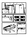
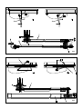
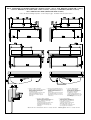
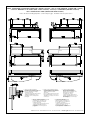
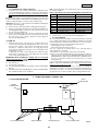
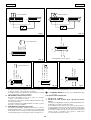
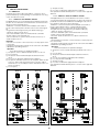
3.3.2. MOUNTING THE SLIDING ARM (fig.6)
1)
N.B.: The default status of the LEDs with the door closed at rest is
shown in bold type.
Mount arm (1) on the operator transmission shaft by means
of the standard shaft (5) and the screw (2) provided (fig.6).
The arm must be fitted pointing 45° outwards as shown in fig.
6(a).
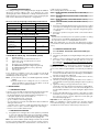
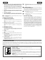
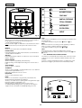
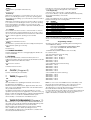
Table 7: Operation of the status signalling LEDs for 950 I/O board
LED
LD1
LD2
LD3
LD4
LD5
LD6
LD7
LD8
LD9
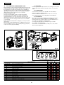
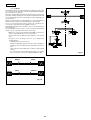
Note: If a larger distance is required between the operator and
the arm use the shaft modular extensions available as accessories,
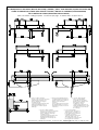
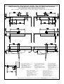
until the required distance is reached (see Table C/D).
Warning: Mount arm (1) on the transmission shaft before fitting the
operator on the lintel (fig.6).
2)
3)
4)
Insert the teflon slide (3) inside the sliding guide (4) (fig.6).
Pull arm (1) inwards manually as shown in fig. 6(b) and secure
the sliding guide (4) by means of two M6 screws on the closed
door as shown in Table C/D.
Check manually that the door is free to open and close fully
and comes to rest against the mechanical travel stops. If the
door does not close correctly, adjust the return spring as
described in paragraph 9.
6)
5)
Run a SET-UP cycle as indicated in paragraph 4.1.
4.1. SET UP PROCESS
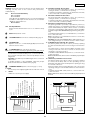
Make the electrical connections to the 950 I/O electronic
control unit as described in paragraph 6, and connect the
mains power supply to the specific terminal (fig.1-ref.10)
ensuring to crimp the earth wire to the lug (fig.1-ref.12)
screwed to the support profile (fig.1-ref.2). Then tighten the
terminal (fig.1-ref.13)
To gain access to the control unit, pass the cables through
the special conduit (fig.1-ref.1) or break the knockout areas
on the casing sides (fig.4-ref.6).
IMPORTANT: When mounting the “sliding” arm or for opening
angles greater than 90°, turn microswitch no. 2 to ON before
connecting power to the system.
2)
3)
4)
OFF
Accessories power absent
Card Reader inactive
Internal sensor inactive
External sensor inactive
Emergency active
STOP safety device active
CL safety device active
Key inactive
Fire-alarm active
Once the system is powered up, hold down SW1 button for at least
5 sec., until the LD2 red LED on the 950MPS board lights up. The LED
will start flashing to indicate that SET UP process is in progress.
During this process the following parameters are set:
- measuring the mass of the door;
- determining the travel stop positions;
The door opens at low speed, then closes half way before
switching back to opening.
Subsequent closure is performed by the return spring.
The process may be inhibited in any of the following conditions:
- function selector switch in the 2 (MANUAL/NIGHT) position or KPCONTROLLER programming unit in MANUAL or NIGHT position.
- incorrect connection of the accessories (electric lock, control/
safety devices);
- incorrect positioning of the programming unit microswitches.
Note: To repeat the initialisation procedure hold down the SW1
button for more than 5 seconds.
Check that door opens and closes correctly by sending an
opening command to one of the following inputs: Internal Sensor,
External Sensor or Key command. Set the trimmers (par.5.2) and
program the microswitches (par.5.4) according requirements.
4. START-UP
1)
ON
Accessories power present
Card Reader active
Internal sensor active
External sensor active
Emergency inactive
STOP safety device inactive
CL safety device inactive
Key active
Fire-alarm active
Close the door.
Power up the operator.
Check that the green LEDs LD1 and LD3 on the board 950MPS
light up.
Check that the status signalling LEDs on the board 950I/O are
in the default status shown in Table 7 .
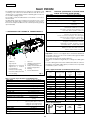
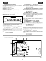
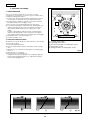
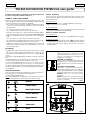
5. 950MPS ELECTRONIC CONTROL UNIT
5.1 LAYOUT AND DESCRIPTION
40VDC
CONNECTOR
MOTOR
CONNECTOR
ADJUSTING TRIMMER
SIGNALLING LED
MICROSWITCHES
25
RS-232 CONNECTOR
Fig. 8