1
EC 90
SUPERVISOR
User's
Manual
Document No.: 85081
Issue:
3
Date:
August 2000
Offices and Service Centres
Asia:
7th Floor Corporation Sq., 8 Lam Lok St, Kowloon Bay, Kowloon,
Hong Kong.
Tel: (852) 2757 3033
Fax: (852)2757 1767
Belgium:
Chausée de Haecht 1801, 1130 Bruxelles, Belgium.
Tel: (32) 2245 8686
Fax: (32) 2245 2235
Canada:
430 Lucknow Drive, Unit15, Mississauga, Ontario L5S 1V3 Canada.
Tel: (1) 905 677 7130
Fax: (1) 905 677 6859
Germany:
Salzbergstrasse 2, 38302 Wolfenbuttel-Salzdahlum, Germany.
Tel: (49) 5331 30080
Fax: (49) 5331 78883
Italy:
Via delle Gardenie 33 (Pontina Vecchia Km 33,400), 00040
Pomezia Roma, Italy.
Tel: (39) 6914 7123
Fax: (39) 6914 7136
Sweden:
Box 20105, Tappvägen 24, 161 02 Bromma, Sweden.
Tel: 46 8 799 6950/1/2/3 Fax: (46) 8281005
United Kingdom:
Grant Way, Isleworth, Middlesex TW7 5QD U.K.
Tel: (44) 0181 560 3171
Fax: (44) 0181 568 2103
USA:
PO Box 9004,18111 South Santa Fe Avenue, Rancho Dominguez,
CA90221, USA.
Tel: (1) 310 637 7500
Fax: (1) 310 632 5519
The material in this manual is for information purposes only and is subject to change without notice. Strand
Lighting assumes no responsibility for any errors or omissions which may appear in this manual. For
comments and suggestions regarding corrections and/or updates to this manual, please contact your nearest
Strand Lighting office.
El contenido de este manual es solamente para información y está sujeto a cambios sin previo aviso. Strand
Lighting no asume responsabilidad por errores o omisiones que puedan aparecer. Cualquier comentario,
sugerencia o corrección con respecto a este manual, favor de dirijirlo a la oficina de Strand Lighting más
cercana.
Der Inhalt dieses Handbuches ist nur für Informationszwecke gedacht, Aenderungen sind vorbehalten. Strand
Lighting uebernimmt keine Verantwortung für Fehler oder Irrtuemer, die in diesem Handbuch auftreten. Für
Bemerkungen und Verbesserungsvorschlaege oder Vorschlaege in Bezug auf Korrekturen und/oder
Aktualisierungen in diesem Handbuch, moechten wir Sie bitten, Kontakt mit der naechsten Strand LightingNiederlassung aufzunehmen.
Le matériel décrit dans ce manuel est pour information seulement et est sujet à changements sans préavis. La
compagnie Strand Lighting n’assume aucune responsibilité sur toute erreur ou ommission inscrite dans ce
manuel. Pour tous commentaires ou suggestions concernant des corrections et/ou les mises à jour de ce manuel,
veuillez s’ll vous plait contacter le bureau de Strand Lighting le plus proche.
Information contained in this document may not be duplicated in full or in part by any person without prior
written approval of Strand Lighting. Its sole purpose is to provide the user with detailed operational
information for the equipment supplied. The use of this document for all other purposes is specifically
ii
User’s Manual
I s s u e 2
prohibited. Certain features of the equipment described in this document may form the subject of patents or
patent applications.
Manual Copyright August, 2000, Strand Lighting Limited. All rights reserved.
Safety Information and Warning
The WARNING signs are to draw your attention to situations that could result in personal
injury or even death, if ignored.
The CAUTION sign draws your attention to a situation that could cause serious damage to
the equipment.
The STOP sign draws your attention to an action that should be taken, or a fact that should
be considered carefully for optimum equipment performance.
Safety Information and Warning
iii
General Information
This equipment operates at voltage levels that are potentially lethal. Do
not touch any of the internal parts of the equipment unless you are fully
aware of the hazards involved and the precautions to be taken. It is
imperative to provide an adequate earth conductor for the rack and load
connections. Do not rely on earthing via conduit or trunking.
The equipment described in this manual is designed and manufactured to comply with international
safety standards IEC 950 and is intended for use as part of a lighting control system. It must not be
used for other purposes where there is any risk of safety to persons. It is important that installation be
carried out in accordance with the instructions given in this manual and in compliance with applicable
electrical regulations. The work should be carried out by a suitably qualified electrician.
The system is designed to be permanently installed with supply and load wiring permanently connected.
In the interests of continued safe and reliable operation, observe the following guidelines:
• Keep the equipment at a room temperature of 0-35°C and a relative humidity of 10-95% (noncondensing) during operation. For operation between 35°C and 40°C de-rate the maximum load by
4% per °C.
Do not, under any circumstances, operate the equipment above 40°C or in an environment
that may become wet.
• Avoid sudden extremes of temperature, rain, direct sunlight or other heat sources.
• Make sure that wires and cables are routed sensibly and wired in accordance with local
regulations.
• DO NOT drop the equipment or subject it to excessive bumping or jarring.
• DO protect the unit from excessive dust or other contamination.
iv
User’s Manual
I s s u e 2
Table of Contents
Offices and Services.....................................................................ii
Safety Information and Warning ................................................. iii
General Information .....................................................................iv
Introduction and Assistance ........................................................1
Manual Organisation...................................................................... 1
Definitions ..................................................................................... 2
Conventions ................................................................................... 4
Technical Assistance...................................................................... 4
Problems........................................................................................ 4
Technical Questions ....................................................................... 4
Parts Purchases.............................................................................. 4
Comments and Suggestions ............................................................ 4
Addresses ...................................................................................... 4
Operational Features ....................................................................5
Configuration................................................................................. 5
Inputs ............................................................................................ 6
Outputs.......................................................................................... 6
Programming Rack Functions ........................................................ 7
Load Status Reporting ................................................................... 8
Security Features ........................................................................... 8
SWC™ (System Wide Control)...................................................... 9
Outlook™ ...................................................................................... 9
Reporter PC™ Software ................................................................ 9
Dimmer Characteristics.................................................................10
Regulation ....................................................................................10
Output ..........................................................................................10
Special Power Modules .................................................................10
Efficiency .....................................................................................10
Servicing ......................................................................................10
Hardware Description .................................................................11
Dimmer Rack................................................................................11
Central Interconnection Card.........................................................12
SWC Port .....................................................................................12
RS232 Port...................................................................................13
PANIC Switch..............................................................................13
Miniature Circuit Breakers............................................................13
Contracting Access .......................................................................13
Rack Capacity ..............................................................................13
Size & Weight (Approx.) ..............................................................13
Power Distribution........................................................................14
Supply Voltage .............................................................................14
Central Interconnection Card.........................................................16
Control Circuit Isolation................................................................16
Table of Contents
v
Optional Power Supply (part no 76421) ........................................16
Ventilation ....................................................................................17
Processor Module .........................................................................18
Processor Options .........................................................................18
Power Modules .............................................................................19
Connector .....................................................................................19
Circuit Protection..........................................................................19
Output Voltage .............................................................................20
Line Compensation .......................................................................20
DC Component of Output .............................................................20
Filter Risetime ..............................................................................20
Hard Firing...................................................................................20
Load Status Reporting ..................................................................20
Using With Fluorescent Lamps......................................................20
Module Types...............................................................................21
Installation................................................................................... 23
Configuration Kit..........................................................................23
Environmental Considerations .......................................................23
Power Requirements .....................................................................24
Single Phase Operation .................................................................24
Conduit Layout.............................................................................24
Phase Wiring ................................................................................24
Load Wiring .................................................................................26
Control Wiring..............................................................................28
Connection Between Racks ...........................................................29
Fan Fail / ......................................................................................29
Overtemp Sensors .........................................................................29
Reporter PC Control Wiring..........................................................30
DMX512 Dimmer Control Wiring.................................................31
AMX192 Control Wiring ..............................................................32
D54 Control Wiring ......................................................................33
SWC and Digital Network Control Wiring ....................................34
PANIC Wiring..............................................................................36
Automatic PANIC Settings ...........................................................36
Other Contact Connections............................................................37
Automatic Backup Setting.............................................................37
How Dual Electronics Systems work .............................................38
Fanfail/Overtemp Warning and Processor Active LED Wiring.......38
Analogue Control..........................................................................39
Analogue Output...........................................................................40
Hardware Setup ............................................................................41
Select Dimmers for PANIC ...........................................................41
Check All Wiring ..........................................................................42
Apply System Power.....................................................................42
Processor Configuration................................................................43
Startup .........................................................................................43
Front Panel Programming.......................................................... 45
Navigating the System...................................................................46
The Keypad and Key Lock ............................................................46
vi
User’s Manual
I s s u e 2
Fields............................................................................................48
Default Display.............................................................................50
Main Menu ...................................................................................52
Set Levels .....................................................................................52
Outlook Presets Menu ...................................................................54
Recording and Recalling Presets....................................................55
Set Channel Levels........................................................................55
Set Fade Times .............................................................................55
Set the Power Up Preset ................................................................56
SWC Preset Menu ........................................................................57
Activate a Preset ...........................................................................58
Record a Preset.............................................................................59
Set the No Mux Preset ..................................................................60
Set Fade Time...............................................................................61
Mux Inputs Menu .........................................................................62
Patching Menu..............................................................................65
Patch Dimmers to Rooms..............................................................66
Set the Starting Address ................................................................67
Patch Dimmers to Mux Signals .....................................................68
Patch Dimmers to Analogue Signals ..............................................69
Set the Starting Circuit Number ....................................................70
Set Individual Circuit IDs..............................................................71
Dimmer Curves Menu...................................................................72
Set Incandescent Dimmer Curves ..................................................73
Set Fluorescent Dimmer Curves ....................................................74
Set Dimmers to Non-Dim..............................................................75
Dimmer Response Menu ...............................................................76
Event Report Menu .......................................................................76
Rack Config Menu........................................................................77
Set Language ................................................................................78
Set Slot Type ................................................................................78
Set Slot Types Automatically ........................................................79
Set Rack Number..........................................................................79
Set Maximum Output Voltage.......................................................79
Set Minimum Dimmer Levels........................................................80
Set Key Lock Status......................................................................80
Set Fan Speed Control...................................................................80
Set the Active Processor................................................................80
Set Time and Date ........................................................................81
Edit User Curves...........................................................................82
View Serial Number......................................................................83
View Panic Map ...........................................................................83
Set Current Reporting mode ..........................................................83
Set Cable Compensation values.....................................................83
Return the Rack to Default Settings...............................................84
Set all Default...............................................................................84
Clear Profile .................................................................................85
Default SR Config ........................................................................85
Calib Menu...................................................................................86
Set LCD Display Contrast ............................................................87
Set Mains V Scaling .....................................................................88
Set Phase Filters ...........................................................................89
Table of Contents
vii
Set AMux I/P Scaling ...................................................................89
Set Analogue Input Scaling ...........................................................90
Set Analogue Output Scaling.........................................................91
Set Dimmer Phase.........................................................................91
Check Memory Values ..................................................................91
Event Reporting Configuration ......................................................91
Error Log......................................................................................92
Event Reporting .......................................................................... 93
Reporter PC™ Software ...............................................................93
Event Report Menu .......................................................................94
Dimmer Events .............................................................................95
Learning Dimmer Loads................................................................96
Important note about learning loads...............................................97
Live Status ...................................................................................97
Enable/Disable Reporting..............................................................97
CBTrip Mode ...............................................................................97
Profile Statistics............................................................................97
Communications Statistics ............................................................97
Basic Troubleshooting ............................................................... 99
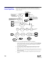
Understanding the Control Signal Path ........................................100
Failure & Status LEDs................................................................101
Special Note for Reporting modules ............................................101
Error Log....................................................................................102
Startup Errors.............................................................................103
Loading New Software................................................................104
Replacing Major Parts ................................................................106
Servicing Power Modules............................................................106
Replacing....................................................................................106
Processor Modules......................................................................106
Reconfiguring a Processor Module ..............................................107
Isolating Problems ......................................................................108
System Problems.........................................................................108
Individual Dimmer Problems .......................................................112
Reporting Dimmer Problems .......................................................113
Fluorescent Dimmer Problems.....................................................113
Periodic Maintenance............................................................... 115
Index .......................................................................................... 117
viii
User’s Manual
I s s u e 2
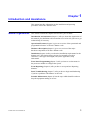
Chapter 1
Introduction and Assistance
This manual provides information on the installation and operating
procedures for EC90sv dimmer racks.
Manual Organisation
This manual contains the chapters shown below, plus an Index.
Introduction and Assistance (chapter 1) tells you about the organization of
this manual, plus definitions and conventions used. Also tells you how to get
technical help, if necessary.
Operational Features (chapter 2) gives an overview of the operational and
programmable features of EC90sv dimmer racks.
Hardware Description (chapter 3) gives an overview of the major
hardware components in EC90sv dimmer racks.
Installation (chapter 4) tells you about the installation requirements for the
dimmer rack. This chapter shows pinouts for externally accessible
connectors, cable types and lengths, and (where applicable) setup
information.
Front Panel Programming(chapter 5) tells you how to use the menus in
the processor module to configure the system.
Event Reporting (chapter 6) tells you how to set up and use Reporting
dimmers.
Basic Troubleshooting (chapter 7) tells you how to begin troubleshooting
if you have problems with dimmers or the rack.
Periodic Maintenance(chapter 8) lists the steps which should be taken to
keep the equipment running at its best.
Introduction and Assistance
1
Definitions
The following definitions are used throughout this manual:
Channel Device controlling a dimmer or group of dimmers. Historically, there is a
physical controller (such as a slider) for each channel. On most current
control systems, channels are numbers accessed by a numeric keypad. Each
channel can control multiple dimmers.
CIC (Central Interconnection Card). The printed circuit board on which all
contractor control wiring connections are made. It is located on a slider
mechanism in the fan tray.
Circuit Connection device and wiring for providing power to a lighting fixture from
a dimmer.
Circuit ID A unique identification number containing up to four digits which you can
assign to each dimmer. The circuit ID may be the same as the dimmer
number, or may be a special number used to indicate circuit location, phase,
channel number, etc. This feature is useful for System Wide Control and
Reporter™ PC functions.
Crossfade A fade which contains both an up-fade and a down-fade. Also may refer to
any fade where the levels of one cue are replaced by the levels of another
cue.
Cue The process of recalling a preset from its memory location and putting the
result on stage.
Preset, memory, and cue are often used interchangeably.
Curve The relationship between a control level and the actual dimmer output. Also
known as “dimmer law.”
Dimmer law See “curve.”
Dimmer Device controlling power to a lighting fixture by use of phase control
techniques.
Default The original factory settings.
Fade A gradual change in stage levels from one set of intensities ("look") to
another.
Fade time The time it takes for dimmer levels to go from their current levels to the
levels in the selected preset. Each preset has its own fade time.
Hard fired dimmer Standard dimmers use a fraction of the load current to power the thyristor
control cicuitry but hard fired dimmers use independent power supplies.
Hard fired dimmers provide more stable outputs when used with very small
loads (less than 60W), fluorescent ballasts, cold cathode lighting, and
inductive loads.
Level A numerical value used to express the “brightness” of a dimmer. Usually
shown as %.
2
User’s Manual
I s s u e 2
Mux Abbreviation of the word “Multiplex”. Multiplex systems transmit data
(usually dimmer information) from a lighting controller to a dimmer rack
via a single cable rather than via a pair of wires for each dimmer.
Patch Historically, the process of physically connecting circuits to dimmers. Now
usually refers to electronic assignment of dimmers to channels.
Phase The three phases of the mains supply to which the dimmers are connected
are identified as phase 1, phase 2 and phase 3 in Europe and phase A, Phase
B and Phase C in North America.
Power module A chassis containing one or two dimmers or contactors. This is sometimes
referred to as a “dimmer.” However, each EC90sv power module can have
one or two dimmers or contactors in it, so this manual distinguishes between
dimmers (individual power control circuits) and power modules (a
collection of one or more power control circuits).
Preset A pre-defined setup of intensities for a set of channels, stored in memory for
later replay. For Outlook applications, the EC90sv processor module stores
8 programmable presets per room for up to 16 rooms. For SWC
applications, the processor module stores 99 programmable presets. Preset
0 (ZERO) is always a blackout.
Preset fade time See “Fade Time.”
Rack number A number used to uniquely identify each dimmer rack in a multiple rack
system. Rack numbers are set from the front panel of the processor module,
and are usually set by the installation engineer.
Room An area separately defined for purposes of architectural lighting control
(e.g., Outlook control stations). This is usually either a room in the
traditional sense (an indoor enclosed area) or a portion of a room which can
be partitioned off. Each room may be separately and simultaneously
controlled by the system.
Status Reporting Status Reporting dimmer or contactor modules are able to measure output
voltage, current, DC voltage and temperature. This advanced feature
enables rack software to determine if the module is working correctly, and
the nature of the load.
SWC (System Wide Control) A method of programming and controlling more
than one dimmer rack simultaneously. A hand held controller lets you
program and recall all 99 presets and control individual dimmers. 8 and 16
channel pushbutton stations and an A/V interface, let you recall any 8 or 16
of the 99 presets at each station. Please contact Strand Lighting or see the
System Wide Control Data Sheet or System Wide Control User’s Manual
(part number 85061) for details on how SWC works.
Reporter PC™
Introduction and Assistance
PC Software that runs under Microsoft Windows and lets you set up certain
Strand Lighting dimming cabinets and racks (including EC90sv racks).
Please contact Strand Lighting for details.
3
Conventions
The following additional conventions are used in this manual.
ESC
Shows the actual push-button labelled "ESC."
ON (all capital text) shows the status of a function or switch, as in "Turn the
switch ON".
Input (text with first letter capitalized) shows the actual menu selection for menu
displays with text selections (e.g., Fan speed can be set to Fixed or
Variable).
Patch (bold text with first letter capitalized) shows a menu name (e.g., Patch
menu).
Operational Features (italic text) refers to a specific chapter or section name, and to specific
menu items. Also used for emphasis in notes.
Technical Assistance
EC90sv racks and dimmers require a minimum of maintenance and
servicing. See chapter 6 for basic troubleshooting procedures and chapter 7
for periodic maintenance procedures.
Problems If equipment fails to operate properly upon installation, or under normal
load and temperature conditions and basic troubleshooting procedures are
not effective, please contact Strand Lighting Field Service at the office
serving your area.
Technical Questions For technical questions regarding setup, operation, or maintenance of this
equipment, please contact the Strand Lighting Field Service office serving
your area.
Parts Purchases For purchase of spare parts or documentation, please contact the Strand
Lighting office serving your area.
Comments and For comments regarding equipment functions and/or possible
Suggestions improvements, or for comments on this manual, please call or write to the
Marketing Department at the Strand Lighting office serving your area.
Addresses Addresses for all of the Strand Lighting offices are shown on page ii of the
front section of this manual.
4
User’s Manual
I s s u e 2
Chapter 2
Operational Features
This chapter presents the basic operational features of the EC90sv rack.
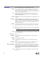
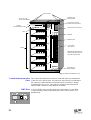
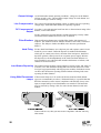
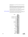
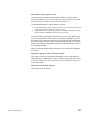
Configuration
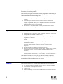
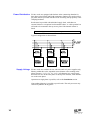
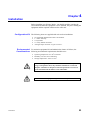
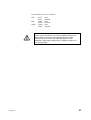
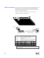
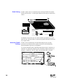
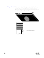
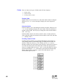
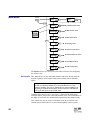
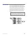
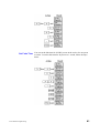
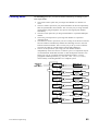
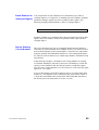
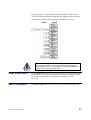
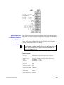
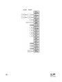
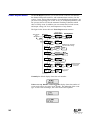
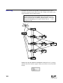
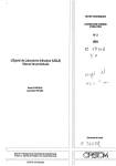
Large racks have provision for up to 36 dimmer modules. Small racks have
provision for up to 18 dimmer modules. The modules are arranged in crates
(see figure below) and can accept certain combinations of Module types.
CENTRAL
INTERCONNECTIONCARD
FANTRAY
RACKPROCESSOR
ISOLATOR
SWITCH
(Optional)
MASTER
CRATE
BACKUP
CRATE
BLANKMODULES
CRATE 3
CRATE 4
CRATE 5
CRATE6
Any 3kW crate can accept any 3kW module, any 6kW crate can accept any
6kW module. The top crate is always the ‘Master’Crate containing the rack
processor; the second crate must also be a Master in the case of dual
electronics racks.
Rack processor modules are available with 36 or 72 dimmer control outputs
to drive EC90sv dimmers. If dual electronics is required, 72 way rack
processors must be fitted to both crate 1 and 2 positions (shown as Master
and Backup above) and a dual electronics type rack specified at the time of
manufacture. This applies to both large and small racks. 72 channel
Operational Features
5
processors also have 12 Analogue Outputs (0 to +10 volts at 1mA
maximum) for auxiliary control.
The following configuration items are usually programmed in the factory or
during commissioning, but can also be reprogrammed by the user, and
should be checked at commissioning time.
• The processor display language. This can be English, French, German, or
Spanish.
• The module types for each rack slot position. From this information,
dimmers and analogue outputs are given sequential dimmer numbers to
simplify programming. Slot types for Reporting modules are automatically
updated if module types are interchanged.
• Rack number (1-99). This number is used by the Reporter PC software.
• PANIC selection and configuration.
Inputs
The following control inputs are available for EC90sv dimmer control.
• Multiplex A input, selectable for SMX / DMX512, AMX192, or D54 inputs.
• Multiplex B input for SMX / DMX512 only.
• 32 (72 channel processor) or 16 (36 channel processor) analogue inputs
patchable to any dimmer.
• Digital Network Control for Outlook™ and compatible architectural control
stations.
• SWC™ (System Wide Control) for remote preset panels, A/V interface and
hand held programmer.
• Connection for communicating with a PC running the Reporter PC™
Windows based software; or Strand’s 430/530 consoles running
Reporter™ .
• Rack keypad and LCD display to program all functions.
• RS232 port for a local PC running Reporter PC™ , enabling setup, playback,
show memory storage, operating software upgrades, and full status
monitoring.
• External switch contacts for main/backup processor selection, MuxA/MuxB
selection, PANIC enable/disable, “Go to Preset 1,” and “Go to Next Preset.”
All control conections are via 2-part plug-in screw terminal connectors
housed in a unit called a Central Interconnection Card (CIC). The CIC is
mounted on a sliding mechanism for easy access.
Outputs
The following outputs are available from the EC90sv processor module:
•
•
•
•
12 Analogue Outputs (72 channel processor only) for external equipment.
Fan fail/module overtemp LED connection.
PANIC active.
Master and Backup processor active LED connections with dual electronics
systems
6
User’s Manual
I s s u e 2
Programming Rack
Functions
Several additional functions are generally accessed or programmed in the
field by the user as required:
• Maximum output voltage (per dimmer): 50-250 volts (e.g. set to 230V for
extended lamp life).
• Minimum level (per dimmer): 0% - 100% (e.g. set to 10% for aisle lights or
large lamp preheat).
• Room and channel patching (for applications using Outlook and other
Digital Network Control compatible stations).
• Each dimmer and analogue output can be patched to any valid SMX /
DMX512, AMX192, or D54 address number for the standard multiplex
input A (Mux A). Dimmers can only be patched to valid SMX /DMX512
address numbers for multiplex input B (Mux B).
• Circuit ID-used by SWC and Reporter PC software.
• Curve assignment (per dimmer): Linear, Square, S-Curve, Fluo Elec (for
electronic fluorescent balasts), Fluo Mag (for magnetic fluorescent balasts)
and Non-Dim. The two fluorescent curves let you set the top end voltage
and the bottom end cutoff voltage. The Non-Dim curve lets you set the turnon threshold for the Non-Dim. An additional 5 user defined curves can be
programmed at the rack, or downloaded from the Reporter PC software.
• Dimmer response (per dimmer): fast (30ms), normal (100ms) or slow
(300ms). This determines a dimmer's rate of response to a change in control
level. Slow is usually set for large tungsten loads to reduce filament inrush,
medium or fast for small loads.
• Dimmer control assignment (per dimmer). The way in which the various
input levels combine is determined on a per dimmer basis by setting the
dimmer Mux mode; these outputs are:- Outlook preset, SWC preset, Mux A,
Mux B, and analogue (“Input”) or to a fixed level (0% - 99% or "Full").
• Record and recall presets (1-8, ON and OFF per room for Outlook control,
and 0-99 per rack for System Wide Control).
• Define Preset Number or "Hold" condition on Mux failure.
• Define power-up preset per rack for Outlook presets.
• Calibrate top set between 7 and 13 volts for analogue inputs.
• Calibrate top set between 0 and 10 volts for analogue outputs.
• Set LCD contrast.
• Error log accessible from the processor module or Reporter PC software.
• Dimmer reporting enable/disable (load status reporting dimmers only).
Operational Features
7
Load Status
Reporting
All EC90sv dimmer modules, including contactor Non-Dims and hard fired
dimmers, are available in load status reporting versions. Load status
reporting versions of dimmers can be mixed in any combination with
standard dimmers in EC90sv racks. These dimmers report many status
items back to the rack processor. The processor can then determine a wide
range of faults with diagnostic data. Reported items include:
•
•
•
•
•
Security Features
Dimmer type.
Dimmer output current.
Dimmer output voltage.
Dimmer temperature.
Excess DC output from dimmer.
In order to minimize the impact of failures to any part of an EC90sv a
number of security features are provided with, or are optional with the
racks.
Standard security features for EC90sv racks are:
•
•
•
•
•
•
•
•
•
•
2 fans, in case one fan fails.
Fan fail indication per fan.
Overtemperature sensors in each module.
The processor module can be set to hold the last dimmer levels forever, or to
fade to a specified SWC preset after a preset interval in cases of multiplex
signal failure.
Setup data is stored in non-volatile memory.
Memory card can be easily moved on exchange of processors.
2500V opto-isolation of Mux A and Mux B DMX512 inputs, SWC input,
Outlook input, Reporter input and external switch contact inputs.
Any of 72 dimmers and 12 Analogue Outputs (72 channel processor only)
can be assigned to PANIC with a mechanical switch. PANIC can be
activated (full ON) from the dimmer rack front panel or from a remote
momentary contact switch. This activation does not require processor
intervention. It is strictly hardware activated. (Requires optional PSU Part
No. 66100).
Automatic PANIC on removal or failure of processor module. In racks with
two processor modules, both modules must be removed to activate PANIC
(requires power supply as above).
Keypad lock.
Optional security features for EC90sv racks include:
• Redundant tracking backup (requires a second processor module fitted to the
rack).
• Optional automatic switch over from failed processor to working processor,
or Panic on failure of both.
• Setup data can be transferred between processors if either processor is
replaced.
• Reporter PC software lets you store setup data off-line.
• Backup processor activated by remote switching.
8
User’s Manual
I s s u e 2
SWC™ (System
Wide Control)
SWC lets you control multiple EC90sv racks from a single location. A hand
held controller lets you program and recall all 99 presets and control
individual dimmers. 8 and 16 channel pushbutton stations let you record or
recall any 8 or 16 of the 99 presets at each station. An audio visual (A/V)
interface is also available to activate presets from external contacts. Contact
Strand Lighting or see the System Wide Control User's Manual for details
on SWC operation.
Outlook™
Outlook is a comprehensive family of control stations designed for
architectural applications needing a simple, flexible control solution with
minimal installation and cabling costs. Outlook stations require the optional
PSU, Part no. 76421, to be fitted. These control stations can access,
modify, and recall lighting levels stored in the EC90sv processor module.
Features and options include:• Control up to 16 separate rooms, with up to 12 channels per room.
• 8 preset scenes plus ON and OFF for each room.
• Manual sliders (3, 6, 9, or 12 sliders per station) for direct control of
individual circuits.
• Record facility for saving slider levels for future pushbutton recall.
• Programmable fade times between 0 and 4 minutes from Outlook control
stations or 0 to 10 minutes from the rack processor or Reporter PC software.
• Record lockout facility for playback-only operation.
• 1, 4, and 8 preset pushbutton stations.
• Audio-Visual interface.
• Room combine stations for room partitioning.
Reporter PC™
Software
Reporter software running on a PC under Microsoft Windows lets you
control multiple EC90sv racks. This software lets you remotely program all
processor features and download an additional 5 user programmable
dimmer curves.
Reporter PC software lets you access rack and dimmer status information:
Operational Features
•
•
•
•
•
•
•
•
•
•
No load
Load error (deviation from recorded load)
Overload
CB trip
Overheat
Thyristor or Contactor short circuit
Thyristor or Contactor open circuit
High DC
Module swap
SRP fault
•
•
•
•
Mux A and Mux B input fail.
Phase fail A, B or C
Fanfail warning.
Panic mode activated
9
•
•
•
•
Processor Enabled (master or backup)
Tracking OK
Input line voltage per phase, and total load current per phase
Earth Leakage Fault (special EC90sv systems only)
Contact Strand Lighting or see the Reporter Software User's Manual, part
number 85083, for more details on Reporter PC operation.
Dimmer
Characteristics
Since the control electronics for all dimmers is in the processor module,
dimmer characteristics are determined by both the dimmer itself and the
control electronics.
Regulation Line regulation acts on each individual dimmer and maintains dimmer curve
parameters (set curve, max voltage, min level).
Output
• The output response curve can be set to Linear Power, Square, S-Curve,
Fluo Elec (for electronic fluorescent ballasts), Fluo Mag (for magnetic
fluorescent ballasts), and Non-Dim. The two fluorescent settings let you set
the top end voltage and the bottom end cutoff voltage. The Non-Dim setting
lets you set the turn-on threshold for the Non-Dim. 5 additional user
programmable curves are available.
• The output waveform is a variable conduction angle sine wave (230VAC).
• Dimmer response can be set to fast (30ms), normal (100ms) or slow
(300ms). This determines a dimmer’s rate of response to a change in control
level. Slow is usually set for large tungsten loads to reduce filament inrush,
medium or fast for small loads.
• A special smoothing algorithm is applied to small level changes to maintain
smooth fades even with very long fade times.
• 5 user curves are set to 1:1 by default, and can be programmed by the rack
keypad or from the Reporter PC.
Special Power Modules EC90sv power modules are available in thyristor dimmer/non-dim,
contactor non-dim and hard fired thyristor versions for use in a variety of
situations. All modules are available with load status reporting as an
optional feature. Contactor non-dims can be used for motor loads,
capacitive loads, HMI ballasts, or any other load that does not respond well
to phase controlled dimming. Hard fired dimmers are particularly useful for
fluorescent, cold cathode, and other inductive loads.
Efficiency The power efficiency of the dimmer is a minimum of 97% at full load. The
power efficiency of contactor non-dims is 100%. The Power output is
approximately 10Btuh per Amp of connected load.
Servicing
EC90sv dimmer racks are designed to be easily serviced in the field. They
incorporate:
• A single connector card (CIC) for all control connections making
installation and maintenance an easy task.
• Highly reliable, oversized power module contacts.
• Replaceable processor module(s).
10
User’s Manual
I s s u e 2
Chapter 3
Hardware Description
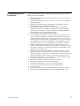
The EC90sv dimmer rack is a free standing, factory assembly of welded
steel construction finished in thermally set powder coat paint with bolt-on
covers. The rack and all crates are earth grounded.
Fixing holes are provided so that racks can be bolted together and to the
floor. Eye bolts are provided for attaching to the top of the rack for lifting
purposes.
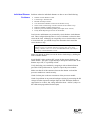
Dimmer Rack
Each EC90sv dimmer rack consists of the following:
• 6 (large rack) or 3 (small rack) crate versions containing up to 36 power
modules or 18 power modules respectively.
• 1 or 2 rack processors.
• Central Interconnection Card (CIC) for all external signal connections.
• 2 ventilation fans.
• Individual circuit breakers for each dimmer.
• RS232 port.
• Reporter PC port.
• SWC/Outlook port.
• PANIC switch.
• Indicators for low voltage power, 3 phase power, Fan fail and PANIC.
• Optional power supply for SWC / Outlook ancillaries (76421)
• Optional Isolator switch.
The top crate contains the rack processor, and for dual electronics versions
the second crate must also contain a rack processor; both processors are
identical. The first position in all subsequent crates are occupied by blank
modules. The connectors in the rack are polarized to prevent dimmer
modules being plugged into slots of the wrong rating.
Power distribution is by five 30x10mm copper bus bars rated at 600A each.
Module configuration within crates is detailed in chapter 2.
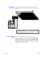
Hardware Description
11
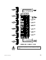
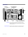
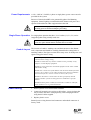
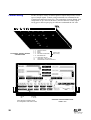
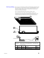
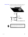
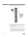
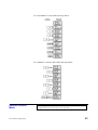
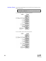
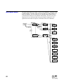
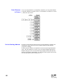
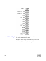
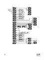
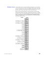
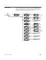
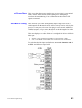
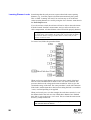
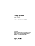
Eye Bolt Positions
50mmHOLE FOR
SIGNAL WIRING
APERTURE FOR
POWER WIRING
OUTLOOK/SWC STATION
POWERSUPPLY(OPTIONAL)
CENTRAL
INTERCONNECTIONCARD
ISOLATORSWITCH(OPTIONAL)
FANS
BUSBARS
BUSBARFUSES
ALLENSCREW
( Door Release )
CRATES
N.B Each dimmer has its own
circuit breaker housed in the
door section (not shown)
APERTURE FOR
POWER WIRING
LOADCONNECTORTERMINALS (12 0ff)
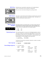
Central Interconnection The Central interconnection Card (CIC) is housed in the top compartment
Card of the rack above the fan units. All contractor signal wiring is terminated to
the connectors underneath this card and the unit is mounted on a sliding
mechanism for easy access. This card also contains some configuration
links and DIP switches to select dimmers for PANIC.
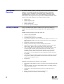
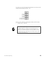
SWC Port A six pin XLR socket provides an interface with Strand’s System Wide
POWER
Control allowing remote programming and recall of all 99 presets via a
handheld unit.
RS232
12
User’s Manual
I s s u e 2
RS232 Port The RS232 port is provided for connecting to a PC running Reporter
software, allowing local status reporting or configuration.
POWER
This port is also used for down loading rack operating software.
RS232
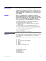
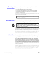
PANIC Switch The PANIC switch will bring selected dimmers to full and can be used in an
emergency situation such as mux or control desk failure. The dimmers are
selected by switch banks located on the CIC.
POWER
RS232
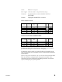
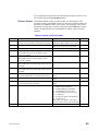
Miniature Circuit Individual modules are protected by their own circuit breakers which are
Breakers mounted adjacent to the crates in the rack door, allowing modules to be
isolated and removed without shutting down the rack. The rating of these
breakers will vary according to the size of module installed.
• 3kW
• 6kW
• 10kW
16A
32A
50A
Contracting Access The contracting chamber is accessed via a full height hinged door which is
secured by an allen screw situated in the right hand pillar. The door opens
more than 90º to allow free access to the chamber. Power cable entry is via
the top and bottom of the racks and provide access onto the bus bars. The
bottom aperture is located within the contracting chamber.
• Top Aperture :
• Bottom Aperture :
400 x 400mm
358 x 285mm
Cable entry for signal wiring is through a 50mm hole, suitable for conduit,
in the top of the rack.
Rack Capacity
Size & Weight (Approx.)
• Large rack:
• Small rack:
• 6 Crate Rack (large)
Height:
1968mm
Depth:
510mm
• 3 Crate Rack (small)
Height:
1168mm
Depth:
510mm
Hardware Description
36 Dimmer modules
18 Dimmer modules
Width:
Weight Loaded:
Weight Empty:
905mm
450kg
200kg
Width:
Weight Loaded:
Weight Empty:
905mm
250kg
130kg
13
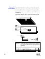
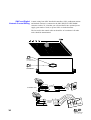
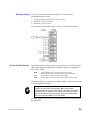
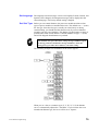
Power Distribution EC90sv racks are equipped with busbars in the contracting chamber for
three phase plus Neutral and Earth connections. Busbars are rated at 600A
per phase and are provided with M12 bolts for fitting with proprietary cable
clamping hardware.
Racks must be provided with individual supply feeds, with either an
external isolator or an optional rack mounted isolator. A cable spreader box
will need to be mounted to the top access plate if the internal isolator is
fitted.
The mains supply must not be looped through from one rack to another.
Typical configuration is shown below.
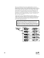
Supply Voltage EC90sv racks are available for use with 220-240VAC power supplies only.
Phasing within the rack is sequential across dimmer crates running in the
phase sequence:- L1, L2, L3, L1, L2, L3. All dimmers in a vertical stack
down the rack are on the same phase. In dual power modules, both dimmers
are on the same phase.
Operation on single phase is possible, refer to the Installation section.
Non-standard phasing is possible to special order. The rack processor may
control any dimmer on any phase.
14
User’s Manual
I s s u e 2
It is imperative that an adequate Earth conductor for the rack and
load connections are provided. Do not rely on Earthing via conduit or
trunking.
Hardware Description
15
Central Interconnection All contractor connections for control lines are by plug-in screw terminals.
Card For signals that must be bussed from rack to rack, two terminal block
connections are provided, one for input, the other for output. Strand
Lighting supplies appropriate link cables for rack interconnection in
multiple rack systems.
The chassis is secured to the rack by a sliding mechanism. Loosening two
thumb screws allows the chassis to slide out and drop down for easy access
(see rack drawing on page 12 ).
The (CIC) contains terminals for control of the following:
• Mux A / B Inputs: SMX / DMX512, AMX, D54.
• Contact Inputs: for master/backup selection of processors, Mux A/B
selection, ‘Goto’preset selection and external PANIC switch
enable/disable.
• Analogue Inputs: for external connection to analogue lighting desks
such as LX.
• Analogue Outputs: +10v supply at 1mA max for high impedance
inputs.
• SWC / Digital Network Connections: Outlook stations, A/V
interfaces, SWC units.
• Reporter PC connections: for linking to the PC monitoring system.
• LED outputs: for fan fail/module overtemp, panic, processor active
(master or backup - for dual electronics systems)
The CIC also houses the switch banks for selecting dimmers for the PANIC
function, Analogue Outputs and termination links for the mux signals.
Control Circuit Isolation Opto Isolation between high voltage and control electronics is 3750 VAC.
All control inputs, apart from Analogue Inputs, are also isolated from the
processor electronics at 2500VAC, offering double optical isolation
between the controller and the high power circuits.
Optional Power Supply Each EC90sv rack can have an additional power supply for powering up to
(part no 76421) 25 Outlook or SWC wallstations. In addition, this power supply will drive
dimmers in Panic mode when no processor is fitted or the processor power
supply has failed. The power supply is mounted in the contracting chamber,
(see page 12).
16
User’s Manual
I s s u e 2
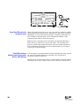
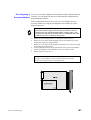
Ventilation
Adequate ventilation must be provided to maintain an ambient operating
temperature within the range 0 to 35ºC and humidity of 45-90% noncondensing. Special attention should be paid to the need to maintain ambient
temperature within these limits when racks are enclosed in a small room.
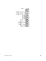
Air flow is from the top of the rack, as shown in the diagram, supplied to an
air plenum at the rear of the rack, by two tangential fans and exhausted
through slots in the front of each dimmer module. No air is vented over the
dimmer power connectors ensuring clean contacts.
EC90sv racks are designed to operate with only one fan working and for a
minimum of 30 minutes with no fans working. Air flow sensors monitor fan
operation and report inadequate air flow to the rack processor module in the
top crate.
Removal of modules in a rack will affect the pressurisation of the air
plenum at the rear of the rack. Although EC90sv can operate with up to
10% of its modules removed, it is recommended that removed modules are
either replaced by spare units or the slots filled by blank modules.
The optional Reporter PC software will report the current fan speed setting
("FIXED" or "VARIABLE") and any fan failure. In additon, the fan fail
LED on the front of the rack will flash if one fan has failed and remain on
constantly if both fans fail. The remaining fan is driven to full to
compensate.
Hardware Description
17
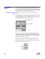
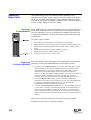
Processor Module Each EC90sv rack contains one or two processor modules. Each processor
module has an 8 character by 2 line backlit LCD allowing simple setup and
control at the rack. This display normally defaults to Rack: 01. If there are
any dimmer events reported, the display will show appropriate messages
with an event count.
Pressing the > key takes you into a series of setup menus to view and set up
the more frequently used EC90sv features. See the Front Panel
Programming chapter for details on accessing these functions.
+ - keys give a set of current status messages.
All programmed data is held in battery maintained RAM on the processor
module daughter board for up to 6 months without power to the rack.
Processor Options
The rack can be equipped with one or two processor modules. The second
processor module acts as a fully tracking backup, and can be automatically
or remotely activated by a switch contact. The configuration data from
either processor is transferred into the other processor automatically. The
currently inactive processor always tracks the currently active processor.
18
User’s Manual
I s s u e 2
Power Modules
Connector Power and control circuit connections are made through a standard
connector. The module connector and the receptacle in the rack contain
polarising inserts for the purposes of ensuring the modules cannot be fitted
into the wrong locations.
Circuit Protection Each dimmer module is wired through to an appropriately sized thermomagnetic circuit breaker of either 6kA or 10kA fault current rating.
Hardware Description
19
Output Voltage At full load under normal operating conditions, voltage loss in the dimmer
will not exceed 8 volts. The maximum output voltage for each dimmer can
be limited through a software setting.
Line Compensation The system will regulate the dimmer outputs to within 1volt over operating
voltage range. Each individual dimmer is separately regulated.
DC Component of Less than 1 volt with tungsten loads from 60w to the maximum rating of the
Output dimmer, at all control levels.
EC90sv load status reporting dimmers include monitoring circuitry which
will shut down the dimmer if excessive DC is detected.
Filter Risetime High specification dimmer types include filter chokes with risetimes of
450µsec. The standard 230VAC dimmer includes a filter with a risetime of
100µsec. The 450µsec chokes meet BBC noise emission specification
PID/171.
Hard Firing EC90sv hard fired dimmers use a thyristor pair and separate control circuit
board for power control. Unlike the thyristor in standard fired dimmers,
which gets its control power from a fraction of the load power, hard fired
thyristors get their control power from a separate power supply. Because
the thyristors are fired independently of the load, hard fired dimmers are
more suitable for use with loads that include transformers or ballasts, cold
cathode or fluorescent tubes.
Load Status Reporting The optional status reporting system requires a load of at least 100 watts (at
230VAC) on a 3kW module to distinguish between load and no load. This
level goes up proportionately with larger power modules. Individual circuits
can have their load status reporting disabled without affecting load status
reporting for other dimmers.
Using With Fluorescent If fluorescent lamps are to be used with EC90sv then hard fired dimmer
Lamps types are recommended (see above). With small loads, it is possible that the
RFI filter networks (used to ensure compliance with EN55014) may cause
input to output leakage even when dimmers are turned off. The networks
may be removed by cutting a link, for each relevant channel, inside each
module.
If these links are cut, then you must ensure compliance with EN 55014 by
other means.
20
User’s Manual
I s s u e 2
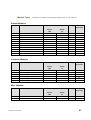
Module Types
Modules are available in the following configurations for 220 / 240VAC.
Dimmer Modules
Part no.
Description
230V
Firing
Status
Reporting
72411
72412
Type A Module
Type B Module
Power
kW
dual 3kW
dual 3kW
Choke
µs
100
100
std
std
4
72421
72422
Type C Module, hi-spec
Type D Module, hi-spec
dual 3kW
dual 3kW
450
450
hard
hard
4
72431
72432
Type E Module, hi-spec
Type F Module, hi-spec
6kW
6kW
450
450
hard
hard
4
72435
72436
Type G, hi-spec, double-width
Type H, hi-spec, double-width
10kW
10kW
450
450
hard
hard
4
Firing
Status
Reporting
hard
hard
hard
hard
4
Contactor Modules
Part no.
72441
72442
72443
72444
72445
72446
Description
EC90sv,
EC90sv,
EC90sv,
EC90sv,
EC90sv,
EC90sv,
Type
Type
Type
Type
Type
Type
U, Module
V, Module
W, Module
X, Module
Y, Module
Z, Module
230V
Power
kW
3kW + c
3kW + c
c + 3kW
c + 3kW
2xc (3kW)
2xc (3kW)
Choke
µs
450
450
450
450
4
4
Misc. Modules
Part no.
72491
72492
Description
EC90sv Blank Dimmer Module
EC90sv Bypass Module
Hardware Description
230V
Power
kW
Choke
µs
3kW/6kW
N/A
Firing
Status
Reporting
N/A
no
21
Chapter 4
Installation
Before installing your EC90sv Racks, you should carefully consider the
environment in which the equipment is to be installed, the power feeding the
equipment and the required conduit and/or cable runs.
Configuration Kit The following items are supplied with each rack on installation:
•
•
•
•
•
Set of Module Identification letters and numbers.
1 x 5mm Allen key.
4 x Eye Bolts.
4 x 6 way female connectors.
Analogue Input connector set, part no.76311.
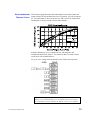
Environmental To maximize equipment life and minimize the chance of failures, the
Considerations following environmental requirements should be met:• Operating temperature: 0 to 40°C ambient.
• Humidity: 5%-95% non-condensing.
• Storage temperature: -40°C to 70°C.
Warning
Dimmer rack efficiency is at least 97%. Since the remainder of the
energy is dissipated as heat, they should be installed in a room with
adequate ventilation to dissipate a heat load equivalent to at least 3%
of the maximum load the dimmer racks will handle.
This equipment is for indoor use only!
Caution
Installation
23
Power Requirements A 220 - 240VAC, 50/60Hz, 3 phase or single phase, power source must be
provided for the system.
Because of electrical and RF noise generated by phase fired dimming
equipment, Strand Lighting recommends that the dimmer rack power be a
separate feed and that no other equipment share the feed.
Do not install this equipment with power applied. Make sure that your
incoming power is disconnected before proceeding.
Warning
Single Phase Operation For single phase operation the three ‘Live’busbars (L1, L2, L3) can be
strapped together using suitably rated wire.
The max. current allowable in single phase operation is 600A, dictated
by the size of the Neutral busbar, and must not be exceeded.
Warning
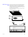
Conduit Layout The location of conduit / trunking runs and their entrance to the dimmer
rack is important and should be carefully planned before cutting holes or
attaching conduit. The figure overleaf shows entry areas for both power and
signal wiring plus busbar wiring.
Do not run power feed or load wires in the same conduit or wireway as
control and low voltage wiring.
Do not run load cable trays and/or conduit in close proximity to any
computer or CRT display equipment.
Do not run wiring from other unrelated equipment in the same conduit
with EC90sv wiring.
Do not enter control wires from dimmer rack locations marked for load
or power wires, and vice versa. These locations are chosen to minimize
electrical interference between various sections of the system.
Do not use alternative control cables to those specified by Strand
Lighting. EC90sv systems are designed to be installed in a specific
manner.
Do not substitute plastic conduit for metal where conduit is called for;
metal conduit acts as a ground and shield.
Phase Wiring
1. Remove plastic covers from busbar terminals.
2. Connect all external power wiring to the busbars, via any isolator that
may be fitted, and secure with proprietary cable clamping hardware
using the M12 bolts supplied.
3. Replace plastic covers.
Internal power wiring between load connectors and module connectors is
factory wired.
24
User’s Manual
I s s u e 2
Installation
25
Load Wiring
Connect only AC lighting loads to this equipment.
Warning
Individual 3 terminal connections are provided for each dimmer output and
these are located at the left hand side of the contracting chamber in line with
the respective crate. Load cables may exit through either access plate and
can be secured to the cable ladder on the right hand side of the chamber.
Connectors are colour coded as follows:GREY
Live
BLUE
Neutral
GREEN /YELLOW
Earth
A crate of 6kW Single dimmer units will use connectors 1-6 whilst a crate
of 3kW dual dimmers will use connectors 1-12.
26
User’s Manual
I s s u e 2
Load terminal wire size is as follows:3kW
6kW
10kW
Caution
Installation
4mm2
4mm2
10mm2
10mm2
25mm2
25mm2
solid
stranded
solid
stranded
solid
stranded
Dimmer control involves fast waveform switching and care must be
taken to ensure that this does not result in radiated interference or
induced fields. It is therefore important that the the two load
conductors for each circuit carry equal and opposite current
components, achieved by running the two conductors together as a
pair of equal length.
27
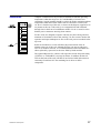
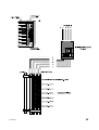
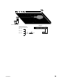
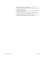
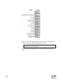
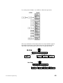
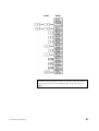
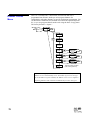
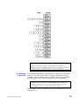
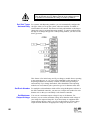
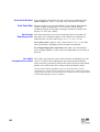
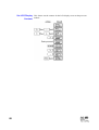
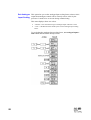
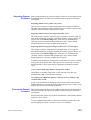
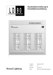
Control Wiring
EC90sv accepts a variety of control signals as inputs and provides several
types of output signals. Control wiring connections are terminated at the
Central Interconnection Card (CIC). The connections between dimmer rack
components are pre-wired at the factory and all contractor control signal
wiring goes to the two part plug in connectors underneath the CIC unit.
3
1
2
5
7
6
4
9
8
10
16
11
12
13
14
1-2
3-4
5-6
7-8
9 - 10
EXTERNAL SIGNAL WIRING
CONNECTORS
15
CONTACT INPUTS
MUXA
MUXB
SWCDIGITAL NETWORK
REPORTERLINK
Paired for easy
daisy chaining
11 - 14 ANALOGUE INPUTS
15
ANALOGUE + LEDOUTPUTS
16
PROCESSORACTIVE LEDOUTPUTS
ANALOG
INPUTS
252627282930 3132+10GND
LK1
LK2
LK14
LK15
17 1819 20 21222324+10GND
1------PANIC------12
1 2 3 4 5 6 7 8 +10 GND
TERMINATION
MUXBDMX/SMX
CD80SV
LK3
49-----PANIC-----60 61-----PANIC-----72 73-----PANIC-----84 85-----PANIC-----96
13-----PANIC-----24 25-----PANIC-----36 37-----PANIC-----48
TERMINATION
MUXADMX/SMX
1-ANOUTPUTS-12
9 10 11 12 1314 1516+10GND
LK17
LK18
LK19
TERMINATION
SWC/DIGITAL
TERMINATION
REPORTER
ENABLELEDS 1 2 3 4 5 6 7 8 9 101112O/T GND
MSTRBKUPGND
PANIC
ANALOG
1
CONTACT INPUTS
1
MUX A
1
1 2 3 4 5 6 7 8GNDGND
TERMINATION
MUXAD54
ISO5V
OK
ISO5V
OK
1
SWC/DIGITAL
NETWORK
MUX B
1
OUTPUTS
1
1
REPORTER
LINK
SLAVE PROCESSOR
AUTO
PANIC
1
TEST
AUTO
BACKUP
TERMINATION
MUXBD54
EXTERNAL
ISOLATED
+/- 12VOK
EXTERNAL
ISOLATED
+/- 12VOK
Panic switches, termination points
andconfiguration links shown in bold
OVERHEAT
FANFAIL
PANIC
PANIC
CENTRAL INTERCONNECTION
CARD- CIC
28
User’s Manual
I s s u e 2
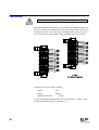
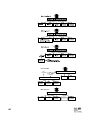
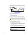
Connection Between If a single control console is to drive dimmers in more than one rack, the
Racks multiplexed control signal must be daisy-chained to all of the racks in which
it is to be used. Duplicate parallel sockets are provided for these signals to
make daisy chaining easier. Factory assembled cables are available to
interconnect racks to save time on-site.
Fan Fail / In the event of a single fan failure, the fan fail LED will flash and the other
Overtemp Sensors fan will be driven to full speed. In the event of both fans failing, the same
LED will remain on constantly. If a reporting dimmer indicates an
overtemperature condition, the LED will also flash, and the fans will be
driven to full.
A external fan fail indicator LED can be connected (see page 29). The
individual rack signals are usually daisy-chained together so that any rack
activates a console or other indicator.
Each module has its own safety overtemperature cut-out. On reporting
modules, an overheat warning will be given before the module thermal cutout operates with a flashing red LED on its from panel, and by the rack’s
fan fail/overtemp LED. Note that BOTH dimmers in a dual module will be
disabled when the cut-off operates.
Non-reporting modules indicate cut-off by their green output LEDs going
out, and there is no warning.
Installation
29
3
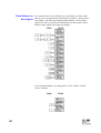
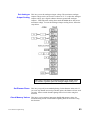
Reporter PC Strand Lighting equipment uses standard US-style 6-pin RJ11 telephone
Control Wiring style connectors for wall boxes and extensions to connect the Reporter PC,
and terminal block connections inside the EC90sv racks for data signals
from the PC. The RS485 converter supplied with the Reporter PC software
has a 6-pin RJ11 connector on its output. There are two pluggable terminal
blocks wired in parallel on the CIC to allow easy daisy-chaining of signals
to multiple racks.
The last rack in the control cable run should be AC terminated. All other
racks should be unterminated.
ACTERMINATION
(LASTRACK IN SYSTEM)
TERMINATION
REPORTER
NOTERMINATION
(ALL OTHERRACKS)
TODIMMERRACK
1
2
3
4
TO WALLBOX
3
1
RJ11 6-way SOCKET
Cable:
Max Length:
Belden 9841/42 or equal.
Standard RS485 electrical characteristics apply, including line
driver and receiver characteristics, line loading, and multi-drop
configurations.
Connector:
Dual parallel terminal blocks in rack, labelled REPORTER
LINK. RJ11 6-pin connectors in wall boxes.
RJ11 RJ11 pin
Wire
Pin
no.
Signal Comments
Pairs color
1
2
3
1
3
4
COMMON
DATA 1DATA 1+
signal common (shield)
data signal complement
data signal true
pair 1
shield
black
red
30
User’s Manual
I s s u e 2
DMX512 Dimmer Control The two types of connections provided in Strand Lighting equipment for
Wiring DMX512 dimmer control signals are the 5 pin XLR style connector and
terminal blocks. EC90sv dimmer racks use pluggable terminal block
connections. Wall boxes and consoles use XLR style connectors. There are
two pluggable terminal blocks wired in parallel on the CIC to allow easy
daisy-chaining of signals to multiple racks.
The last rack in the control cable run should be DC terminated. All other
racks should be unterminated.
DCTERMINATION
(LAST RACKINSYSTEM)
TERMINATION
TERMINATION
MUXADMX/SMX MUXBDMX/SMX
NOTERMINATION
(ALL OTHERRACKS)
TODIMMERRACK
2
3
1
3
TOXLRWALL BOX
2
1
Cable:
Max Length:
Belden 9841/42 or equal.
Standard RS485 electrical characteristics apply, including line
driver and receiver chracteristics, line loading, and multi-drop
configurations.
Connector:
Dual parallel terminal blocks in the rack, labelled MUX A and
MUX B. "XLR" style connectors in wall boxes and on control
consoles.
XLR Terminal
DMX
Wire
Pin
number
Signal Comments
Pairs Color
1
2
3
Installation
1
2
3
COMMON
DATA 1DATA 1+
dimmer common (shield)
dimmer drive complement
dimmer drive true
pair 1
shield
black
red
31
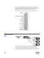
AMX192 Control Wiring The two types of connections provided in Strand Lighting equipment for the
AMX192 signal are the 4 pin XLR style connector and terminal blocks.
Unless otherwise specified, dimmer racks use terminal block connections
and consoles use XLR style connectors.
AMX192 is only supported on the MUX A input of EC90sv racks.
AMX192 control lines are not terminated.
TODIMMERRACK
1
23
45
1
3
TOXLR
WALL BOX
2
4
Link to pin 5
Cable:
Belden 9156 or equal. May use Belden 8723 for
adapters under 100 feet (30m) long.
Max Length: 1000 feet (300m) must be Daisy chained - no
branching runs.
Connector:
Dual parallel terminal blocks in rack, labelled MUX
A. "XLR" style connector on control consoles.
XLR Terminal
Belden Belden
Pin number
Signal Comments
8723 9156
4
2
1
3
2
3
5
4
CLOCK CLOCK +
COMMON
ANALOGUE
clock complement
clock true
Analogue common
multiplexed Analogue
Green
White
Black
Red
Black
White
Black
Red
CLOCK+ and CLOCK- are one twisted pair. Analogue and Common
are one twisted pair.
32
User’s Manual
I s s u e 2
D54 Control Wiring The two types of connections provided in Strand Lighting equipment for the
D54 signal are the 3 pin XLR style connector and terminal blocks. Unless
otherwise specified, dimmer racks use terminal block connections and
consoles use XLR style connectors.
D54 is only supported on the MUX A input of EC90sv racks.
D54 control lines do not usually require termination. However, in
installations with very long runs or significant electrical interference, the
termination link may be fitted in the last rack in the control cable run.
TERMINATED
TERMINATION
MUXAD54
NOT TERMINATED
TODIMMER RACK
4
5
1
TOXLRWALL BOX
3
Cable:
Belden 9156 or equal.
Max Length: 1000 feet (300m). must be Daisy chained - no branching runs.
Connector: Terminal blocks in rack, labelled MUX A. "XLR" style connector
on control consoles.
XLR Terminal
Wire
Pin
number
Signal
Comments
color
1
2
3
Installation
5
GND
4
SIGNAL
ground
not used
multiplexed Analogue signal
Black
White
Red
33
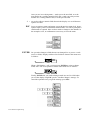
SWC and Digital Control wiring from SWC hand held controllers, SWC pushbutton stations
Network Control Wiring and Outlook stations is connected to the SWC/DIGITAL NETWORK
connector on the CIC. Note that you will need the EC90sv optional power
supply (part number 76421) to power SWC or Outlook stations.
The last rack in the control cable run should be AC terminated. All other
racks should be unterminated.
ACTERMINATION
(LAST RACK IN SYSTEM)
TERMINATION
SWC/DIGITAL NETWORK
NOTERMINATION
(ALL OTHERRACKS)
6
1
23
4
5
Not Used
2
TOSWC
WALL BOX
TODIMMERRACK
1
3
4
SCREEN
Only connected at Rack end
23
1
4
56
Not Used
VTOOUTLOOK
CONTROL
STATION
V+
L+
LSCN
34
User’s Manual
I s s u e 2
Cable:
Belden 9773 or equal.
Max Length: 1000 feet (300m - daisy chained runs only).
Connector:
Terminal blocks in rack, labelled SWC/DIGITAL
NETWORK.
Network :
Unpluggable terminal block on stations.
SWC CONNECTIONS
XLR
Pin
Rack
Term
Signal
Name
1
2
3
4
5
6
4
5
3
2
GND (PWR)
+12V
DATA +
DATA -12V
1
SCREEN
Comments
Pairs
Cable
Color
handheld remote only
pair 3
pair 2
pair 1
N/C
N/C
connect only at rack end
pair 2
black
black
black
red
white
Screen wire
OUTLOOK STATION CONNECTIONS
Station
Terminal
Rack
Term
LL+
VV+
SCN
2
3
6
5
1
Signal
Name
Comments
LAN DATALAN DATA +
-12V
+ 12V
SCREEN
connect to 0 volt line
Pairs Cable
Color
pair 1
pair 2
black
red
white
black
For long runs, if no SWC socket boxes are fitted, pair 3 may be used in
parallel with PWR pair2 to lower the cable voltage drop.
If connections must be made in a junction box due to the length of run or
other considerations, these connections must be soldered before installation
of the insulator.
These are not power connections, they are electronic interconnections which
feed data directly to a microprocessor in the processor module. Poor
connections may cause problems by introducing electronic noise into the
system, resulting in poor system operation.
Installation
35
PANIC Wiring PANIC control wires are connected to the CONTACT INPUTS terminal
block as shown below. A remote panic indicator LED may be connected as
shown.
CONTACT INPUTS
1 2 3 4 5 6 7 8 GND
SET PANIC
RESET PANIC
ANALOGUE
OUTPUTS
CONNECTINGMORETHAN
ONE RACKTOANINDICATOR
PANIC
RACK1 PANIC
1 2 3 4 5 6 7 8 9 10 11 12 OT
GND
RACK2 PANIC
1K
RACK3 PANIC
RACK4 PANIC
GND
PANICINDICATOR
In multiple rack systems you can connect PANIC in parallel across more
than one rack. All racks that are connected in parallel will then be activated
by a single switch.
Automatic PANIC PANIC can be automatically activated when the processor (or both
Settings processors in a dual processor system) is removed, and automatically
deactivated when a processor is reinstalled.
To activate automatic panic, install the jumper between pin 1 and pin 2 of
link LK8. To deactivate automatic panic, install the jumper between pin 2
and pin 3 of link LK8. The CIC ships with automatic panic activated.
36
User’s Manual
I s s u e 2
Other Contact You can connect several other external contacts for controlling rack
Connections functions as shown below. These functions are then available remotely and
instantly.
The Mux A/B switch is only relevant when the Muxmode in the Mux
Inputs > Dimmer Muxmode menu is set to “H/W Sel AorB”. Note that
each dimmer can have a different muxmode, a useful feature if you want
to split a rack’s dimmers across two performance spaces.
Automatic Backup Backup can be automatically activated if the active processor fails.
Setting
To turn automatic backup activation ON, install the jumper between pin 1
and pin 2 of link LK9 and set the Proc Control item in the Rack Config
menu to "SelectBy Contact." To turn automatic backup activation OFF,
install the jumper between pin 2 and pin 3 of link LK8. The CIC ships with
automatic backup activation ON and the Proc Control item in the Rack
Config menu set to "SelectBy Contact."
Installation
37
How Dual Electronics When a dual electronics rack powers up, logic on the CIC monitors certain
Systems work signals generated by each processor. If the master is OK, then it is enabled
immediately. If it is not OK, then the backup is enabled, provided that it is
OK. If neither is OK, then panic can be automatically enabled - if the
Automatic Panic Mode is selected (see above).
Both processors constantly receive all signals, and Automatic Backup or
Panic will occur within 0.2s of a processor failure. The currently active
processor continuously updates the inactive processor with any changes to
rack configuration. The inactive processor indicates that it is Tracking or
Updating on its default display.
Fanfail/Overtemp You can connect an external fanfail/overtemp warning LED to the system if
Warning and Processor you wish. The external indicator is connected to the ANALOGUE
Active LED Wiring OUTPUTS connector on the CIC.
Dual processor systems also provide two LED outputs to remotely indicate
which processor is active. Refer to the section on Automatic Backup above.
38
User’s Manual
I s s u e 2
ENABLELEDS
MSTRBKUPGND
Enabled Processor Indicators
ANALOGUE
OUTPUTS
PANIC
CONNECTINGMORE THAN
ONE RACK TOANINDICATOR
1 2 3 4 5 6 7 8 9 10 11 12 OT
GND
RACK 1OT
RACK 2OT
1K
RACK 3OT
GND
RACK 4OT
Installation
39
Analogue Control EC90sv racks have 32 (72 channel processor) or 16 (36 channel processor)
Analogue Inputs. This control signal is combined with the other control
signals according to the Dimmer Mux Mode selected for each dimmer.
These signals are input through four pluggable terminal blocks on the CIC.
25 26 27 28 29 30 31 32 +10 GND
17 18 19 20 21 22 23 24+10 GND
9 10 11 12 13 14 15 16 +10 GND
1 2 3 4 5 6 7 8 +10 GND
10K POT
TYPICAL CONTROL HOOKUP
DIMMER1
40
User’s Manual
I s s u e 2
Analogue Output 72 channel processor modules have 12 Analogue Outputs, which can source
a maximum of 1mA into a high impedance input (minimum 10KΩ). The
circuit shown below represents the driver circuit on the CIC.
12 Analogue Outputs are available on systems fitted with 72 way
processors; these appear in the menus as the last 12 dimmers in the
system. So in a rack with 72 dimmers, these will be dimmers 73 - 84.
The parameters for Curve, Max Voltage, Min Voltage, Response Time
etc., apply to these dimmers too.
Installation
41
Hardware Setup
Once you have finished, the system can be set up as required.
Select Dimmers PANIC, when selected, turns any single dimmer, combination of dimmers,
for PANIC or all dimmers ON, bypassing system electronics.
Select PANIC for a dimmer using the 72 switches located on the CIC
circuit board. In addition, racks with 72 channel processors have 12
Analogue Outputs that can be tied to PANIC with their own set of switches
(labelled AN OUTPUT on the CIC).
Not all racks have a direct numerical relationship between the PANIC
selection switch number and the dimmer controlled by the switch. If a
PANIC selection switch does not control the dimmer you think it should,
use the View PANIC Map item in the Rack Config menu to see which
dimmer the switch controls.
Dimmers and Analogue Outputs with switches ON are switched ON when
you activate PANIC, regardless of their control settings. Dimmers or
Analogue Outputs with PANIC select switches OFF are switched off when
PANIC is activated. Analogue Output ON is approx. +10VDC. Racks are
shipped with all switches OFF.
When PANIC is activated, any Analogue Output set for PANIC will be
sent +10VDC, regardless of how the Analogue Output scaling is set.
Any selected dimmer will be set to FULL regardless of how the
maximum output voltage is set.
Caution
To activate PANIC:
1.
2.
3.
If the processor module is installed, press PANIC on the rack to turn selected
dimmers in the rack ON.
If you have a remote PANIC station, press PANIC on the station to turn
selected dimmers in the rack ON.
If you have the automatic PANIC activation jumper (LK8) set to activate
PANIC on processor removal, removing the processor module will turn
selected dimmers in the rack ON. Systems with two processor modules must
have both modules removed to activate PANIC. You should not use this
method just to activate PANIC, since it will cause wear and tear on the
processor module connectors.
To deactivate PANIC:
1.
2.
If the processor module is installed, press the switch on the rack or on a
remote PANIC station to turn selected dimmers in the rack OFF.
If you have the automatic PANIC activation jumper (LK8) set to activate
PANIC on processor removal, re-install the processor module to turn selected
dimmers in the rack OFF.
Make sure that the reason for removing the processor module has been
checked before re-installing the module.
42
User’s Manual
I s s u e 2
Check All Wiring Before applying power to the system you should double-check all of your
wiring.
1.
2.
3.
4.
5.
Check that all terminals and mechanical fixings are secured.
Check for stray wire strands and make sure wires are correctly restrained and
not in contact with any metal edges.
Check Earth connections.
Double-check Neutral connections and positively verify phase orientation at
the input busbars. Ensure that Neutral has not been confused with a phase;
connecting the unit "across the phases" will do severe damage.
Make a full safety inspection of all load wiring.
Apply System Power 1. Check power to make certain that it is correctly rated. If not, correct before
2.
3.
4.
Installation
proceeding.
Apply power to system.
Make sure that the fans operate.
If system does not function properly, follow the troubleshooting instructions
in Chapter 6 of this manual. If these steps fail, or for assistance with
replacement parts, please call Strand Lighting directly.
43
Processor
Configuration
Once you have applied power you need to make sure that the system is
working correctly and the the processor modules are set properly for the
installation.
Startup When the rack is switched ON, a number of self-tests are run. The system
displays the rack number.
1. Make sure that all status indicators are showing that the system is
operating correctly. The seven LEDs on the front of the rack should
show (from left to right):
• Opto Power Isolated +5V power should be ON.
• Aux. Power supply should be ON (if the rack contains an optional
power supply).
• Fan Fail / Overtemp should be OFF.
• PANIC should be OFF.
• L1, L2, L3 should be ON.
2. Check the following items to make sure they are correctly set in the
processor module:
•
•
•
•
Slot type (see page 77).
Rack number (see page 78).
Starting mux signal number and dimmer protocol (see page 65).
Time and date (see page 80).
3. Other items you may wish to check at this time, depending on your
system configuration, are:
•
•
•
•
•
Dimmer patch (see page 66).
Outlook patch (see page 64).
Language (see page 77).
Max Voltage (see page 78).
Min Level (see page 78).
4.
Switch on all load circuit breakers.
5.
Connect a suitable luminaire to each outlet and check every dimmer using
the SET LEVEL control facility, a suitable control console, or an SWC hand
held controller. Investigate and correct any malfunctions you find.
If any dimmers do not work, stop and check the slot type for the
dimmer. Dimmers will not work if their slot type is incorrectly assigned.
Make sure that all of the modules are in their correct slots and that the
slot type for each dimmer is correctly set in the processor module.
6. If you have status reporting dimmers, denoted by the symbol R on their
front panels, check that their red LED’s are all off when all dimmers are
off. Refer to the chapter on Status Reporting for details of the various
faults that are denoted by the module LED’s.
44
User’s Manual
I s s u e 2
Chapter 5
Front Panel Programming
This chapter gives the basics of how to program the processsor module
from its front panel. In general, it will be easier to do any setup with a PC
running the Reporter PC software, but this interface lets you configure the
rack without a computer. After the initial Navigating the System section,
this chapter is organized by menu, in the order the menus appear in the
processor module Main menu. Each section provides a menu diagram and
gives details on how to select and program EC90sv programmable features
using the processor module keypad and display.
Navigating the System........................................................................46
Default Display..................................................................................50
Main Menu ........................................................................................52
Outlook Presets Menu ........................................................................53
SWC Preset Menu .............................................................................57
Mux Inputs Menu ..............................................................................62
Patching Menu...................................................................................65
Dimmer Curves Menu........................................................................72
Dimmer Response Menu ....................................................................76
Event Report Menu ............................................................................77
Rack Config Menu.............................................................................77
Calib Menu........................................................................................87
Error Log...........................................................................................94
Front Panel Programming
45
Navigating the
System
You can access a range of programmable features through the use of the
processor module’s keypad and 16 character display. The menu system is
designed to minimize multi-level menus and keep operation simple. Menus
can be shown in French, German, Spanish, or English. English is the default
language and this text assumes that English is selected.
The Keypad and Key The keypad has 6 buttons which let you navigate through the EC90sv
Lock menus.
To avoid tampering by unauthorized personnel, EC90sv includes a security
mechanism indicated by a key (on the display. If this key appears, you must
press ESC ENTER simultaneously and hold them for about 2 seconds to
unlock the system before any of the keys will respond.
This feature can be enabled and disabled from the Rack Config menu by
using the Set Key Lock item. When this item is enabled, the processor is
locked automatically after 10 minutes with no keyboard input. When this
item is disabled, the system is always unlocked. The factory default setting
for the Set Key Lock item is “Disabled.”
<>
let you go to a submenu, move between fields, or move along a large
numeric field. An underline cursor shows which field or digit is selected.
Displays with submenus have an arrow in the lower right corner. Press > in
these displays to go to the next menu level.
46
User’s Man
ual
I s s u e 2
Once you are in a working menu, > sends you to the next field, or to the
next number in a scrolling numeric field, and < sends you to the previous
number in a scrolling numeric field, or to the previous field.
+ -
are used to adjust a numeric field shown in the display or to scroll between
options in a field.
ESC
leaves an option or menu and returns you to the previous menu level. Some
options require positive confirmation with ENTER. You will be prompted if
confirmation is required. Since we have made no changes to the dimmers in
the examples so far, no confirmation is necessary to leave the menu.
ENTER
lets you make changes to fields that are not changed live as you use + and (not-Live fields). Displays with not-Live fields are shown in the menu trees
as follows:
When a field displays “All,” you must press ENTER to action a change.
Fields with “All” as an option are shown in the menu trees as follows:
Finally, ENTER lets you confirm changes made in a not-Live field when
you exit the display using ESC get the “Confirm Changes” message. To
cancel the operation once you get the message, press ESC.
Front Panel Programming
47
Fields There are three basic types of fields used in EC90sv displays.
• Display fields.
• Selection fields.
• Scrolling numeric fields.
Display fields
Display fields are used as labels or to show data which cannot be changed.
When you use < or > to move through a display, the cursor skips these
fields.
Selection fields
Selection fields let you scroll through a fixed list of options. When you use
< or > to move through a display, the cursor lands on the first character or
number of these fields. The only way to change the values in these fields is
with + and - keys.
Selection fields can have text values, numeric values, or both. Some text
values allowed in otherwise numeric selection fields are Off, Full, and dash
(“-”, meaning “none”).
Scrolling numeric fields
Scrolling numeric fields let you scroll individual digits of the number to
easily change numbers with multiple digits. Scrolling numeric fields can
also have valid text values (e.g. “All”). When you use < or > to move
through a display, the cursor lands on the ones digit. If the current value is a
text value, the cursor lands on the letter that is in the ones digit position.
Once in a scrolling field you can use < and > to select the digit you want to
increment and then use + or - to increment or decrement the selected digit.
When a digit reaches 9, pressing + again will set that digit to 0 and
increment the digit to its left.
48
User’s Man
ual
I s s u e 2
If you know you want to increment the tens digit only, you can move to the
tens digit while the display still shows “All.”
Some text values allowed in scrolling numeric fields are Off, Full, dash
(“-”, meaning “none”), and Hold.
A word about Analogue Outputs
12 Analogue Outputs are available on systems fitted with 72 way
processors; these appear in the menus as the last 12 dimmers in the
system. So in a rack with 72 dimmers, these will be dimmers 73 - 84.
The parameters for Curve, Max Voltage, Min Voltage, Response Time
etc., apply to these dimmers too.
Front Panel Programming
49
Default Display
The default display lets you access a series of status displays using + and and lets you access the Main menu by using >. The diagram below shows
the status items you can access from the default display.
1
EC90SV
Rack:01
2
EC90SV
v3.1
3
Enabled
Tracking
4
Master
96 ways
EC90SV
Rack:01
ESC
<
+
-
ENTER
>
ESC
+/-
5
Mux A OK
No MuxB
6
Ph1:230V
50Hz100A
7
Ph2:229V
50Hz 95A
8
Ph3:235V
50Hz250A
9
0 Dim.
Events
To
Main
menu
If no dimmer event is
registered, returning
from the main menu
brings you back to the
display from which you
called the main menu.
If a dimmer event is
registered you will
return to the dimmer
events display.
The default displays are information only displays which let you check
several pieces of system information without needing to go through multiple
menu levels. The description numbers below correspond to the numbers
next to the display in the figure.
1.
2.
3.
The Default display shows the dimmer rack type and rack number.
The Version display shows the dimmer rack type and the software version
number.
The Backup display shows which processor is enabled, and whether or not
there is a backup processor. The currently operating processor will show
"Enabled," while the current backup processor shows "Disabled." "Tracking"
in the second row shows that there is a backup processor, while "No Track"
shows that ther is no backup processor. When the backup and main processor
are functioning, both displays should say "Tracking." When the system is
50
User’s Man
ual
I s s u e 2
4.
5.
6.
7.
Front Panel Programming
properly tracking, data is continuously copied from the "Enabled" processor
(Master) to the "Disabled" processor (Backup).
The Size display shows whether the processor is "Master" or "Backup," and
how many dimmers are fitted.
The Mux display shows whether Mux A is currently functioning, and shows
whether Mux B is operational.
The Ph, 2 & 3 displays show the voltage, frequency, and current for their
respective phases. Current will always be 0 (zero) on the processor that is
"Tracking," and on systems without Reporting dimmers.
The Events display shows how many dimmer events are currently active, and
indicates the nature of each event in an auto-scrolling display.
51
Main Menu
From
default
display
Set
Levels
Dim:##/All ENTER
=##%
for "All"
ESC
ESC
EC90SV
Rack:01
ESC
+
ENTER
<
-
>
Outlook
Presets
To Outlook Presets menu
SWC
Presets
To SWC Presets menu
Mux
Inputs
To Mux Inputs menu
+/Patching
To Patching menu
Dimmer
Curves
To Dimmer Curves menu
Dimmer
Respons
To Dimmer Response menu
Event
Report
To Event Report menu
Rack
Config
To Rack Config menu
The Main menu lets you access all of the other sub menus for configuring
the EC90sv rack.
Set Levels This function lets you test individual dimmers and loads directly from the
keypad, regardless of the signals being received from presets and other
inputs.
Since this overrides the control inputs, including the presets, it is
possible to completely disable any or all of the dimmers. Use this
function carefully. It is easy to completely lose control of dimmers by
forgetting to set them back to Input. Levels set here are remembered
even if you shut power to the system OFF.
Normally this control is set to “All=Input”, which lets the Mux inputs,
Analogue Inputs, and presets control the dimmer levels. The relationships of
the inputs to each other are determined by the Dimmer Mux Mode setting.
This control may also be used to set dimmer levels to record SWC and
Outlook presets where there is no conventional lighting control system.
52
User’s Man
ual
I s s u e 2
To set all dimmers to 50% follow the steps below.
To set dimmers 5 and 8 to 90% follow the steps below.
Outlook Presets
Menu
Front Panel Programming
Before using Outlook presets, ensure that the room/channel/dimmer
assignment has been correctly set (see page 65).
53
There are 10 Outlook presets per room. Eight of them (1-8) are user
programmable. Preset 0 is a non-recordable blackout state, preset 9 is all
dimmers full ON and MAN is the current slider settings being received from
an active slider control station. When you record a preset, you record the
actual dimmer levels as they appear in your room. Outlook presets and
SWC presets are completely separated, and separately controlled, even
though they can control the same dimmers. If you are using the SWC hand
held controller, SWC pushbutton controllers, or SWC A/V interface, see
SWC Preset Menu (page 57).
Outlook presets can be recalled and added to the dimmer output on a
“highest takes precedence” (HTP) basis from the processor module keypad
or from a control station. Selecting a preset crossfades the output of the
Outlook preset processor from the previously selected preset to the new
preset in the programmed fade time.
Don’t forget that Outlook presets are not the only source of control in
a EC90sv system. If a dimmer has control input from other sources,
the Dimmer Mux Mode setting for each dimmer determines what
signals appear at the dimmer. If a dimmer is ON from another source,
you may not be able to fade it OFF using Outlook presets. In addition,
the dimmer levels are affected by Max voltage and Min Level settings.
54
User’s Man
ual
I s s u e 2
Recording and You can record the current dimmer output to any of the 8 recordable
Recalling Presets Outlook presets per room.
1.
2.
3.
4.
Set up the lighting state using any means of control.
Use the Record Preset menu item to select a room and preset number.
Press Enter to record the current dimmer levels to the selected preset.
Repeat for any other presets.
You can activate any Outlook preset by using the Recall Preset menu item
to select a room and preset number.
“Recall Preset” changes the lighting levels by activating the preset. It is
not a "blind" viewing facility.
Set Channel Levels You can set channel levels directly from the keypad by selecting their room,
channel number and setting a level. This lets you test individual dimmers
and loads regardless of the signals being received from the different inputs.
Since this overrides the control inputs, including the presets, it is
possible to completely disable any or all of the dimmers. Use this
function carefully. It is easy to completely lose control of dimmers by
forgetting to set them back to Input.
Normally channel levels are set to “All=Input” which lets the Mux inputs,
Analogue Inputs, and presets control the dimmer levels. The relationships of
the inputs to each other are determined by the Dimmer Mux Mode setting.
This control may also be used to control dimmers recording into SWC and
Outlook presets where there is no conventional lighting control system.
Set Fade Times You can set the fade time (up to 10 minutes) for all Outlook presets in all
rooms, for all presets in a specified room, or for one preset at a time by
using the Fade Time Preset menu item.
To set a fade time for the manual faders, select the “Man” setting in the
preset field. Manual fade time is set per room. The default for the manual
preset is ZERO seconds. With a ZERO time set, when you press “Manual”
or “Take Control” on an Outlook slider station the lighting instantly fades
from the current level to the levels set on the sliders. If a manual fade time is
programmed, the channels fade from their current levels to the slider levels
in the programmed time.
Setting the fade times for all presets in all rooms or all presets in one room
will not change the manual fade time. If you move any slider on the station
that currently has control while a manual fade is in progress, the lighting
levels will instantly conform to the current slider levels.
Front Panel Programming
55
Set the Power Up Preset You can select an Outlook preset that will always appear when the system
is powered up (e.g. after a power failure). The default preset is ZERO,
which sets the entire system to a blackout on power-up. Use the Power Up
Preset menu item to select the preset number. This setting applies to all
rooms in the system, so if you select preset 1, then on power-up each room
will fade to its own preset 1.
The No Mux SWC preset can act as an overall system power-up preset if
desired. If a No Mux preset and a Power Up preset are assigned, the
dimmer levels will be combined according to the Dimmer Mux Mode
settings.
56
User’s Man
ual
I s s u e 2
SWC Preset Menu
There are 99 user programmable system wide controller (SWC) presets per
system. Preset 0 is a non-recordable blackout state. When you record
preset, you record the actual dimmer levels as they appear on stage or in
your rooms. If you are using Outlook controllers, see Outlook Preset Menu
(page 53). Outlook presets and SWC presets are completely separated, and
separately controlled, even though they can control the same dimmers.
Any SWC preset can be added to the dimmer output on a highest takes
precedence (HTP) basis by activating it from the processor module keypad,
remotely from the SWC hand held controller, or remotely from a PC
running the Reporter software. When you activate an SWC preset, the
system crossfades from any previously selected SWC preset (or from a
blackout).
Don’t forget that SWC presets are not the only source of control in a
EC90sv system. If a dimmer has control input from other sources, the
Dimmer Mux Mode setting for each dimmer determines what signals
appear at the dimmer. If a dimmer is ON from another source, you
may not be able to fade it OFF using SWC presets. In addition, the
dimmer levels are affected by Max voltage and Min Level settings.
Front Panel Programming
57
Activate a Preset You can activate the dimmer levels of any SWC preset from the processor
module control panel.
“Activate Preset” changes the lighting levels by activating the preset. It
is not a "blind" viewing facility.
To activate SWC preset 3, follow the steps below:
To turn off SWC presets, follow the steps below:
58
User’s Man
ual
I s s u e 2
Record a Preset You can record the current dimmer output to any of the 99 user
programmable SWC presets.
1.
2.
3.
Set up the lighting state using any means of control.
Follow the procedure as shown.
Repeat for any other presets.
To record the current dimmer output to preset 3, follow the steps below:
Set the No Mux Preset
The No Mux preset is the preset the system will fade to if you lose the Mux
signal. What happens to the dimmers if the Mux signal is lost depends on
the No Mux setting.
Hold
Off
1-99
System holds current levels on loss of Mux signal.
HoldTime submenu is disabled if this option is selected.
System fades to black on loss of Mux signal.
System fades to selected SWC preset on loss of Mux signal.
The default setting is No Mux=Off. No Mux=Hold is a useful safety feature
in live performance situations.
Setting NoMux to Hold may cause problems if the dimmers are left
ON after the control desk is turned OFF. Many desks produce
unwanted signals as the power fails, and once the desk is turned OFF,
the dimmers are susceptible to noise pickup on the Mux Input. This
can leave the dimmers unexpectedly ON. If you set NoMux to Hold,
make sure unattended dimmers are turned OFF.
To assign preset 5 as the “backup” with a Hold Time of 30 seconds, follow
the steps below.
Front Panel Programming
59
In the above example, when both Muxes fail, the system will hold the last
levels for 30 seconds and then fade into SWC preset 5.
When you select a new preset for the No Mux preset, the hold time is
automatically reset to 10 seconds.
To set the system to hold levels on loss of Mux signal, follow the steps
below.
60
User’s Man
ual
I s s u e 2
Set Fade Time You can set the fade time for all SWC presets in the rack or for one preset
at a time. To set the fade time for all presets to 1 second, follow the steps
below.
Front Panel Programming
61
Mux Inputs Menu
The Mux input protocol for Mux A can be set to DMX512, AMX192, D54
or SMX formats. The Mux input protocol for Mux B is either DMX512 or
SMX. In addition, you can set the way in which the input signals interact
(called the Mux Mode) for each dimmer individually. This lets you split a
single rack for use with more than one type of input if required, or use
signals from more than one input to control the same sets of dimmers.
"Mux Input"
from
Main Menu
Mux A:
DMX512
Protocol
Mux A:
DMX512
ENTER
ESC
ESC
+/-
Mux B:
DMX512
+/-
Mux A:
AMX192
+/Mux A:
D54
Dimmer
MuxMod
###: MuxA
/All Only ENTER
for "All"
ESC
###: MuxA
Only
+/-
###: MuxB
Only
###: MuxA
htp MuxB
###: MuxB
over A
###: H/W
Sel AorB
###: Pres
over Mux
###: Mux
over Pres
62
User’s Man
ual
I s s u e 2
To set the protocol of Mux A to AMX192, follow the steps below.
The way in which the various inputs interact to create a dimmer signal is
determined by the Dimmer Mux Mode menu item. The diagrams below
show what each of the options means in terms of signal processing.
Front Panel Programming
63
Pres Over Mux
HTP
(normally)
Highest level takes precedence
Over
(If SWCpreset
is not zero)
Highest level takes precedence
Analog
Inputs
SWC
Presets
Mux A
Mux B
Outlook
Presets
Mux Over Pres
Highest level takes precedence
Mux A
Mux B
Analog
Inputs
SWC
Presets
Outlook
Presets
64
User’s Man
ual
I s s u e 2
Patching Menu
The Patching menu lets you allocate dimmer numbering according to your
own requirements.
• The Outlook Patch option lets you assign each dimmer to a channel in a
room.
• The Start Address option lets you patch all dimmers in the rack sequentially
after the specified Mux Start number. This is an easy way to assign the Mux
patch without going through the slow process of assigning each dimmer
individually.
• The Mux Patch option lets you assign each dimmer to a specified multiplex
number.
• The Analog Patch option lets you assign each dimmer to a specified
Analogue Input.
• The CID Start Number option lets you set a starting circuit ID for a rack and
have the software automatically number the ramaining circuits in the rack
from the CID start number. This is an easy way to set up a rack so that the
cicuit IDs are offset by a fixed amount from the Mux adderesses.
• The Circuit ID option lets you assign your own dimmer numbers
independently of the Start Number or Dimmer patch. It is important only for
use with the SWC hand held controller or with the Reporter software. This
facility lets you use your desk's channel numbering scheme, or even a
geographic numbering scheme, (e.g. 100, 101, 102... 110, 111, 112 etc.)
when remotely controlling dimmers in a complete system.
"Patching"
from
Main Menu
+/-
Outlook
Patch
Dim:###
ESC
Rm02Ch14
Start
Address
MuxStart
# ####
ENTER
ESC
Mux
Patch
Mux:#
ENTER
###=####
ESC
Analog
Patch
Dim:###
AnIn:##
Circ ID
Start
Start
=####
ESC
ENTER
ESC
Circuit
ID
Front Panel Programming
CID:###
=####
ESC
65
Patch Dimmers If you are using Outlook (or compatible) controllers you can patch dimmers
to Rooms to specific channels in specific rooms. To set dimmer 2 to channel 1 in room
2, follow the steps below.
Set the Starting Address
In order to assure that all controls operate separate dimmers, multiple rack
installations require that each rack is uniquely numbered and dimmers
assigned accordingly.
In most systems, dimmers are numbered consecutively through the dimmer
racks. The first dimmer in a rack is set to one number higher than the last
dimmer in the previous rack. The following example assumes that the first
rack has 72 dimmers controlled by 72 consecutive Mux signals, and sets the
first Mux B signal for the second rack to 73.
66
User’s Man
ual
I s s u e 2
The Mux address will change as the dimmer number is changed showing
the address that the dimmer is patched to. Remember that any changes
to the patch will be seen on the lighting output as soon as you press
Enter
Front Panel Programming
67
Patch Dimmers to You can patch one or more dimmers to be controlled by one Mux signal.
Mux Signals This lets you re-assign dimmers to different mux signals, or group various
sets of lights.. The following example patches dimmers 1 and 2 to Mux
signal 100. Unless you patch some other dimmer to Mux signals 1 and 2,
neither of these signals will control any dimmers.
You can unpatch dimmers by setting them to ‘Park’, which is situated
“below” channel 1.
68
User’s Man
ual
I s s u e 2
Patch Dimmers to You can patch one or more dimmers to be controlled by any of the 32
Analogue Signals Analogue Inputs (or 16 inputs for 36 channel processor modules). Dimmers
patched to analogue signals can also be patched to Mux signals. The
following example patches dimmers 1 and 2 to Analogue Input 1.
- - means not patched to any dimmer.
Patching a dimmer to an Analogue Input does not unpatch it from any Mux
signals. These two dimmers will now be patched to Mux signal 100 and
Analogue Input 1.
Set the Starting
Circuit Number
The circuit ID feature lets you give 4-number identifications to dimmers,
which lets you control dimmers from multiple sources, even if those sources
do not call the dimmers by the same numbers. Circuit ID's are useful when
using the optional SWC hand held controller or a PC running the Reporter
PC software, both of which let you control large numbers of dimmers easily
and remotely.
In the following example, a 48 dimmer rack is being added to an existing
512 dimmer installation. Since the system (now 560 dimmers) exceeds the
capacity of one DMX512 link, the control console's second Mux output
must be used to control dimmers 513-1024. However, to the rack this signal
appears as 1-512 again.
If you set the starting circuit ID for the new rack to 513 and its Mux Start
number to 1, the dimmers can be controlled by the main control console as
1-48 in the second DMX cable and from the SWC hand held controller or
the EC90sv processor front panel as circuits 513-560.
Front Panel Programming
69
Set Individual Circuit
IDs
This procedure creates Circuit IDs sequentially for all dimmers in the new
rack, starting with the number you specify.
Although it is generally easier to set circuit IDs using the Circ ID Start
menu, you can also set a single circuit ID if necessary.
To set a Circuit ID for dimmer 1, follow the steps below.
70
User’s Man
ual
I s s u e 2
Front Panel Programming
71
Dimmer Curves
Menu
There are 3 incandescent, 2 fluorescent, and one Non-Dim curve
programmed into EC90sv which you can assign to dimmers for
compatibility with other dimmers or specific application requirements. You
can download 5 additional user defined curves from the optional Reporter
PC, or you can program them from the rack using the Rack Config menu.
The factory default is “Square.”
"Dimmer Curve"
from
Main Menu
Dim:##/All ENTER
Linear
for "All"
ESC
Dim:##/All
Linear
+/-
Dim:##/All
Square
Dim:##/All
S-Curve
Dim:##/All
Fluo El
Dim:##/All ENTER
T### C##
for "All"
ESC
Dim:##/All
FluoMag
Dim:##/All ENTER
T### C##
for "All"
ESC
Dim:##/All
Non-Dim
Non-Dim ENTER
##/All=##
for "All"
ESC
Dim:##/All
User X
There are 5 User Xentries
(User 1 through User 5)
If you set a slot type for a contactor module (U, V, W, X, Y, Z), the
dimmer curve is automatically set to "Non-Dim". If you set a slot type
for an incandescent power module, the dimmer curve is set to "Square."
Reporting dimmers and contactors automatically set their slot types.
72
User’s Man
ual
I s s u e 2
Set Incandescent The following graph illustrates the relationship between input signal and
Dimmer Curves output voltages for the incandescent curves. In general, you can use Square
for TV requirements, Linear for theatre use, and S-Curve for architectural
installations or when you need to match older dimmers.
Separate dimming curves are supplied for use with magnetic and
incandescent fluorescent fixtures. You should set these correctly for best
results from your installed fixtures.
To get to curve settings from the default screen, follow the steps below.
If you set a slot type for a contactor module (U, V, W, X, Y, Z), the
dimmer curve is automatically set to "Non-Dim". If you set a slot type
for an incandescent power module, the dimmer curve is set to "Square."
Front Panel Programming
73
Reporting dimmers and contactors automatically set their slot types.
Set Fluorescent The EC90sv rack supports both magnetic and electronic (phase controlled)
Dimmer Curves fluorescent ballasts. For optimum performance you should set the
appropriate fluorescent curve for each of your fluorescent dimmers. The
settings for top end voltage and cutoff voltage are done the same way for
magnetic and electronic ballast curves.
Caution
Note that you must use an appropriate value of topset voltage with
electonic ballasts, or damage may occur. Due to resonant effects, the
actual voltage at the ballast can be higher than the Topset voltage.
Using an RMS meter at the ballast, be sure to set the Topset so that the
ballast manufacturer’s maximum voltage is not exceeded.
Fluorescent lamps operate best when the dimmer response is set to "Slow"
(see page 76 for setting dimmer response).
For additional information on Fluorescent Dimming refer to the Strand
Lighting fact sheet A Guide to Fluorescent Dimming.
To set a dimmer to "Magnetic" with a top voltage (“T”) of 100 and a cutoff
voltage (“C”) of 35V, follow the steps below.
74
User’s Man
ual
I s s u e 2
If the fluorescent ballasts require a heater circuit, you will need to
connect the heater circuit to a separate non-dim or contactor, and then
patch the non-dim to the same control channel as the fluorescent
dimming circuit. The FluoMag setting delays the startup of the dimmed
circuit to allow for a separate heater circuit to turn ON first.
Set Dimmers You can also assign dimmers a Non-Dim curve. When you assign a Nonto Non-Dim Dim curve you also have the option of setting the threshold percentage.
Non-dims remain at ZERO when the controller is below the set threshold
percentage and at FULL when the controller is above the threshold.
In order to keep dimmers from turning ON and OFF with slight voltage
fluctuations if the control is set to the threshold value, non-dims are
acutally turned ON about 2% above the threshold voltage, and not
turned OFF until about 2% below the threshold voltage.
Dimmers that are set to a contactor slot type will automatically be set to the
Non-dim curve.
Front Panel Programming
75
There is a slight difference between the way contactors act and the way
dimmers act when set to Non-Dim. When dimmers are set to Non-Dim, they
are still affected by the Max Voltage, Min Level, and Response Time
settings. When set as contactors, these settings are not applied.
The example below sets dimmer 5 to Non-Dim with a threshold of 40%.
Dimmer Response
Menu
The response speed of a dimmer is the rate at which it responds to an
increase or decrease in its control level. EC90sv provides "Medium"
(100mS), "Fast" (30mS) and "Slow (300mS) response times which you can
assign to all dimmers or to any single dimmer. "Slow" is generally used for
76
User’s Man
ual
I s s u e 2
large lamp loads (e.g. 5kW fittings such as QuartzColor Pollux), while
"Fast" is used for the small lamp loads that you might use in a chase effect.
The following example sets the response of all dimmers to "Fast."
The "Fast" setting together with the accuracy of digital dimmers can
cause very high inrush currents to flow. These may damage large
lamp filaments and cause circuit breakers to trip. Only set dimmers to
FAST if necessary for a particular effect.
Event Report Menu
The Event Report menu lets you turn dimmer status reporting ON or OFF
(per dimmer), “Learn” the characteristics of load status reporting dimmers,
and see the current events for each dimmer (see chapter 6, Event
Reporting).
Rack Config Menu
The Rack Config menu lets you access system functions for initial setup.
Front Panel Programming
77
Language
English
Set
Languag
ESC
"Rack Config"
from
Main Menu
Set Slot
Type
Row:##/All
S:##/All=#
+/-
ENTER
Language
Francais
ESC
ESC
AutoSlot
Type
Language
Deutch
Status:
ENTER
Config/Unconfig
ENTER
+/Set Rack
Number
Rack:##
Number
Set Max
Voltage
MaxVolts
###/All=###V
ESC
Set Min
Level
Language
Espanol
ESC
ENTER
for "All"
MinLevel
ENTER
###/All=##%
for "All"
Key Lock
Disabled
ESC
+/-
Set Key
Lock
Key Lock
Enabled
ESC
FanSpeed
Control
ENTER
FanSpeed
Fixed
ESC
Proc.
Control
SelectBy
Contact
ENTER
+/-
FanSpeed
Variable
ESC
EditUser
Curves
UCI: #
Steps
Step: #
#=#
ESC
ESC
Calib
Menu
To
"Calib"
Menu
View Err
Log
To
"Error Log"
Menu
Set Time
& Date
Disabled
ENTER
SelectBy
Software
+/-
Time
##:##
ENTER
26 Jun
1995
ENTER
ESC
ESC
View
Serial
SerialNo
00001073
ESC
Panic
Map
Dim:##
Panic:##
ESC
Current
Report
ReportOn
Phase:All/1/2/3 ESC
Factory
Setup?
ENTER
Cable
Comp
Dim:##
##/Disabled
Clear
Profile?
ENTER
Are You
Sure?
ENTER
Please
Wait...
ESC
ENTER
+/Set All
Default
Default
SR Cfg?
78
User’s Man
ual
I s s u e 2
Set Language The language used for messages can be set to English, French, German, and
Spanish. Once changed, all subsequent messages will be displayed in the
selected language. The factory default setting is English.
Set Slot Type Before you can control dimmers, the processor module must know what
types of power modules are installed in the rack. The defaults are “-” (none)
for slot type. Since the slot type is usually set at the factory or during
commissioning, you should need this function only if you move dimmers
around or get new power modules. The dimmer type designation (a letter) is
printed on the front of each dimmer. Constant modules are type “-” (none)
and will be skipped when dimmers are patched.
Dimmers will not work properly without the correct slot type setting.
You should at least spot check these settings during installation. If you
are having problems with dimmers during installation, check this
setting first. If you add or move dimmers, check this setting.
The following example sets all dimmers in the rack to type B.
When you set a slot to a contactor type (U, V, W, X, Y, Z) the dimmer
curve is automatically adjusted to “Non-Dim”. If you reset the slot to an
incandescent dimmer type, the curve will be set to “Square”
Front Panel Programming
79
If you change a dimmer type from single to dual dimmer, or vice
versa, the patching for every dimmer after the newly changed slot will
be repatched to accommodate the change in number of dimmers.
Set Slot Types For systems with Reporting modules, you can automatically configure the
Automatically slot types when you set up the system, when new modules are added, or
when modules are moved. This feature will only add modules to the map or
change the types for existing Reporting modules. To remove modules from
the map or to change the type for a non-reporting module, you must use the
Slot Type menu.
This feature is for initial setup, and if you change a module from a reporting
to non-reporting type, or vice versa. Slots identified by this procedure as
Reporting modules are constantly scanned, and their slot type changed
automatically if you change the module. Slots identified as non-reporting
modules are not scanned by the system for type or for dimmer status data.
Set Rack Number For multiple rack installations which will be using the Reporter software or
the SWC hand held controller, you must set a unique rack number for each
dimmer rack so that you can identify racks from the controller.
Set Maximum You can set a maximum output voltage for any or all dimmers. For
Output Voltage instance, you can set the maximum voltage lower than the rated voltage of
your lamps for improved lamp life. If you have lamps or equipment that
cannot tolerate the line voltage, you can use this feature to set the voltage
output from the dimmer to an appropriate voltage for the device. The
80
User’s Man
ual
I s s u e 2
maximum output voltage is applied to all dimmers and dimmers assigned as
non-dims. It is not applied to contactor non-dims. You cannot use contactor
non-dims for devices which need a maximum output voltage setting. For
Analogue Outputs, which are the dimmer numbers above the actual number
of dimmers in the rack, a setting of 250V will give +10VDC at the output.
This sets the maximum dimmer output voltage, not the maximum control
level applied to the dimmer.
Be careful when using a maximum output voltage with dimmers set
for PANIC. When panic is activated, full output voltage appears at
the output of any dimmer or non-dim set for PANIC, regardless of
how the maximum output voltage is set.
Set Minimum You can set a minimum level for any or all dimmers. This can be used for
Dimmer Levels security/safety lighting in locations where you always want at least some
light. It can also be used as a preheat for large lamps. Minimum dimmers
levels are shown in control percentage.
This sets the minimum control level applied to the dimmer, not the
minimum dimmer output voltage.
Set Key Lock Status To avoid tampering by unauthorized personnel, the EC90sv processor
module includes a security mechanism indicated by a key on the right side
of the display. If this key is present, you must press ESC ENTER
simultaneously and hold them for about 2 seconds to unlock the system
before any of the keys will respond.
The Set Key Lock item in the Rack Config menu lets you Enable or Disable
the automatic locking function. When Enabled, the processor automatically
locks if there has been no input for 10 minutes. When Disabled, the
processor is always unlocked.
Set Fan Speed Control The cooling fans in the rack can be set to Fixed or Variable speeds.
Use the Fixed setting where rack room cooling is a problem. With this
setting, the fans are always ON when the dimmer rack is ON.
The variable setting operates on a HTP basis with the dimmers and runs
proportionately, i.e. if only 1 dimmer is at full then the fan runs at full
speed, where as if all dimmers were at 50% the fan would run at approx
half speed.
Increases in fan speed take 1 minute, decreases in fan speed take 5 minutes.
Set the Active In racks with dual processors, the currently active processor can be selected
Processor automatically, by contact, or by software. The default for this feature is
Select By Contact, which lets you select the current processor manually
Front Panel Programming
81
with an external switch or automatically by setting the Auto Backup link
(LK9 on the CIC).
The Select By Software setting is provided for older CIC boards without
automatic backup selection, and emulates this feature in software. You
should not use this setting with new CIC cards. To identify new CIC cards,
look for connector PL49, which is a 3-pin connector labelled "ENABLE
LEDS." This connector did not exist on older CIC boards.
The Disabled setting makes a processor completely passive. It continues to
send the "I'm alive" signals to the CIC. This setting is useful mainly for
disabling the backup processor while loading new software.
Set Time and Date This menu item lets you set the system time and date. System time is set in
24 hour mode (hh.mm.ss). The main reason for setting this correctly is to
ensure that all system reporting is time-stamped correctly.
82
User’s Man
ual
I s s u e 2
Edit User Curves Using the Edit User Curves item in the Rack Config menu, you can edit the
5 user curves for the rack. These curves initially contain 2 steps, at 0% and
at 100%. To change a user curve from its default, specify the curve number,
then the number of steps, then edit the value for each of the steps.
When you first specify the number of steps the software creates the steps
spaced evenly between 0% and 100%. That both 0% and 100% are counted
as steps. To create a curve divided equally into 4 parts you need to specify 5
steps. As you enter new values, the software linearly interpolates between
each pair of adjoining steps. To get a smooth curve, you will need to enter a
considerable number of steps.
Front Panel Programming
83
View Serial Number You can find the serial number for your rack processor module from the
Rack Config menu. This is a view only entry, and cannot be changed.
View Panic Map The panic map lets you see which PANIC switch controls which dimmer.
PANIC switches are numbered 1-72 in every rack, but the dimmer
numbering depends on the numbers and types of dimmers installed. This
display is a “view only” display.
Set Current This menu option lets you set current reporting mode in cases where all
Reporting mode three phases are "strapped" together, or the 3 phases are connected in a
different order. You can set the value to 123, 1, 2, 3, 213, 312 etc.
For 3-phase racks (3-phase 4-wire), set this value to “123”, or one of the
other 5 possibilities, depending on the actual phase arrangement.
For strapped single phase operation(a three phase rack with all phase
busses strapped together), set this value to the single phase you are using in
that rack.
Set Cable The Cable Comp menu lets you set cable resistance (in milliohms) for each
Compensation values circuit. To activate cable compensation, the you must learn the dimmer
loads so that the system knows what current will be drawn at each specified
dimmer level, and therefore what voltage to add to the dimmer output.
You must have Reporting dimmer types to use this function, and an
elevated mains supply will be beneficial to allow you to achieve the output
voltage that you require. Please discuss the benefits of cable compensation
with Strand Lighting in the first instance.
84
User’s Man
ual
I s s u e 2
Return the Rack You can return the entire system to its default values, clear all of the learnt
to Default Settings load profiles or clear event report config limits by using the Set All Default
menu.
Set all Default This menu option sets all values throughout the system to their factory
settings. Since some of the defaults may not be correct for your system,
check all settings after you use this function.
Important
Be careful. This setting returns all programmed settings to their
factory defaults, including setting the slot type for all dimmers back to
“none”. If you use this feature, dimmers will not work until the slot
type for each dimmer is reset.
Dimmer Defaults
Slot Type
All module slot types are cleared. On 72 channel
processors you still have 12 Analogue Outputs.
Dimmer Level
All=Input. Dimmers take levels from control inputs.
Curve
All dimmers = Square
Response
All dimmers = Medium
Max Voltage
230V
Min Level
Off
Fluorescent Topset 195V
Fluorescent Cutoff 80V
Non-Dim Threshold 5%
Dimmer Mux Mode A HTP B
Load profiles
cleared
MCB trip mode
O/P = on
Cable compensation Disabled
Front Panel Programming
85
Status reporting
config values
Factory defaults
Rack Defaults
Rack Number
Rack Language
Fan Speed
Processor Enable Mode
Processor Enabled
Mux Fail Preset
Mux Fail Hold Time
Keypad Lock Enable
Mux Protocol
Mux Patch
User Curves
Analogue Patch
Circuit ID Patch
SWC Fade Time
SWC Preset Levels
SWC Preset Number
SWC Manual Levels
Outlook Fade Time
Outlook Preset levels
Outlook Power Up
Outlook Patch
Outlook Room Links
1
English.
Variable.
Contact.
Yes.
Off. On Mux fail, dimmers fade OFF after 10 seconds.
10 seconds.
OFF.
DMX512 (Mux A and Mux B).
1...n sequential (Mux A and Mux B).
1:1 exact linear.
All inputs disabled and unpatched.
1, 2, 3,...n for both Mux A and Mux B.
5 seconds.
0
0 (blackout)
0
5 seconds except ON preset, which is 0 seconds.
Manual fade time default is also 0 seconds.
P1=All dimmers 100%, P2=85%, P3=70%, P4=60%,
P5=50%, P6=40%, P7=30%, P8=20%
Preset 0. On power-up, no Outlook preset activated.
dimmers 1-12 = room 1, channels 1-12,
dimmers 13-24 = room 2, channels 1-12,
dimmers 25-36 = room 3, channels 1-12,
dimmers 37-48 = room 4, channels 1-12, etc.
All rooms unlinked.
Clear Profile This menu option clears all of the learnt load profiles. This can be handy if
you have decided that learning profiles is too much work due to frequently
changing loads, and want to return the system to a simple load/no load
sensing mode.
Default SR Config This menu option clears all of the Status Reporting configuration limits to
their factory defaults.
86
User’s Man
ual
I s s u e 2
Calib Menu
"Calib"
from
Rack Config Menu
The Calib (calibration) menu is accessed through the Rack Config menu,
and lets you calibrate the various voltages in the rack. The functions in this
menu should rarely need to be accessed, since initial calibration is done at
the factory. This menu requires a password for access.
Password
>####<
LCD Disp
Contras
Contrast
=##%
ESC
Phase
Voltage
Phase #
=119V
ENTER
ESC
ESC
+/Phase
Filters
Do not use without
Strand Field Service
supervision
Anlg Mux
Scaling
Calc###% ENTER
RawM###%
ESC
Analog
Input
Calc###% ENTER
RawA###%
ESC
Front Panel Programming
Analog
Output
Scaling
= ##%
Dimmer
Phase
Do not use without
Strand Field Service
supervision
Memory
Values
Do not use without
Strand Field Service
supervision
EventRep
Config
Do not use without
Strand Field Service
supervision
ESC
87
Set LCD Display This feature sets the contrast for the LCD display screen on the processor
Contrast module.
88
User’s Man
ual
I s s u e 2
Set Mains V Scaling
This option sets the scaling factor the processor uses to adjust for changes
in the incoming mains voltage. It is factory set, and should not need to be
reset. Please consult Strand Lighting field service before using this function.
When you first enter the Mains V Scaling display, the voltage shown is the
current incoming voltage multiplied by the current scaling factor. The
current scaling factor is an internal variable and cannot be directly
displayed or set. To set a new scaling factor for phase B, follow the steps
below.
You must use a true RMS reading DMM for this calibration.
Front Panel Programming
89
90
User’s Man
ual
I s s u e 2
Set Phase Filters This ensures that the processor module zero crossover time is synchronized
with the mains. Please contact Strand Lighting before attempting to
recalibrate the mains phasing. You must not activate this while a MUX
signal is connected.
Set AMux I/P Scaling This option lets you set the Analogue Mux input scaling factor so that a
100% output from the control console will be correctly read as 100% by the
processor. It may need to be reset if you plug in a new console with D54 or
AMX192 outputs, or if you move the console so that the length of the cable
run to the dimmer rack changes drastically.
This menu displays two values if Mux A is configured for D54 or AMX192
Mux input.
• “RawM” is the unscaled average of Mux A input channels 1 and 2.
• “Calc” is the RawM value scaled by the current Mux input scaling factor.
To recalculate the Mux input scaling factor, set console channels 1 and 2
to FULL and follow the steps below.
Front Panel Programming
91
Set Analogue This option lets you set the Analogue Input scaling factor so that a 100%
Input Scaling output from analogue controls will be correctly read as 100% by the
processor. It needs to be set on-site during commissioning.
This menu displays shows two values.
• “RawM” is the unscaled average of Analogue Input channels 1 and 2.
• “Calc” is the RawM value scaled by the current Analogue Input scaling
factor.
To recalculate the Analogue Input scaling factor, set Analogue Inputs 1
and 2 to FULL and follow the steps below.
92
User’s Man
ual
I s s u e 2
Set Analogue This lets you set the Analogue Output voltage. The maximum Analogue
Output Scaling Output voltage can be set from 0V to about 10.5V. To adjust the Analogue
Output voltage, put a digital voltmeter between ground and Analogue
Output 1. Then adjust the scaling factor until the DMM shows the correct
maximum voltage. To reset the Analogue Output scaling factor, follow the
steps below.
When panic is activated, any Analogue Output set for PANIC will be
sent +10VDC, regardless of how the Analogue Output scaling is set.
Set Dimmer Phase This lets you specify non-standard phasing for the dimmers in the rack. If
you reset any dimmer incorrectly with this option, the dimmer will not work
correctly. Please consult Strand Lighting field service before using this
function.
Check Memory Values This lets a service engineer interrogate the SRAM memory values for
troubleshooting. Please consult Strand Lighting field service before using
this function.
Front Panel Programming
93
Event Reporting This lets you change the various values that the rack uses for detecting
Configuration dimmer events. Each dimmer may have different values. Please consult
Strand Lighting field service before using these functions, as incorrect use
will result in many spurious problems.
Error Log
Sometimes, the software may produce an unexpected message, due to
external or internal reasons. Each "Error" has a unique error number and is
logged internally in non-volatile memory. If a message appears, write down
the error number and call your Strand Lighting service agent or dealer.
Press + or - to view all entries in the log. Press ESC to exit from the error
log. You will be prompted to clear the error log or leave it intact.
The error log is discussed in more detail in the Basic Troubleshooting
chapter.
94
User’s Man
ual
I s s u e 2
Front Panel Programming
95
Chapter 6
Event Reporting
This chapter provides information on the event reporting functions of
EC90sv racks with Reporting dimmers. Trouble-shooting guidelines for
Reporting dimmers are included in the Reporting Dimmer Problems section
of chapter 7, Basic Troubleshooting.
All EC90sv dimmer modules, including contactor non-dims and hard fired
dimmers, are available in load status reporting versions. Load status
reporting versions of dimmers can be mixed in any combination with
standard dimmers in EC90sv racks. These dimmers report many dimmer
status items back to the processor. The information can be accessed using
the optional Reporter PC doftware, or through various menu items. Using
this data, the processor can detect a wide range of dimmer and load faults
with comprehensive diagnostic data.
Reporter PC™
Software
Reporter PC software, running under Microsoft Windows lets you log the
following dimmer events with full diagnostic information and time stamp.
•
•
•
•
•
•
•
•
•
•
No load
Load error
Overload
CB trip
Overheat
Thyristor or Contactor short circuit
Thyristor or Contactor open circuit
High DC
Module swap (Slot type changed)
SRP fault
The following rack events or data are detected with time stamps
•
•
•
•
•
•
•
•
•
Fan Failure (one or both fans)
Mux fail A or B
Phase fail A, B or C
Panic mode activated
Processor Enabled (Master or Backup)
Tracking (Master or Backup)
Earth Leakage Fault (special EC90sv systems only)
Input line RMS voltage per phase
Total RMS load current per phase
Contact Strand Lighting or see the ReporterPC Software User's Manual
(part number 85083) for more details on how this software works.
Event Reporting
93
Event Report Menu
The Event Report menu lets you see the current events for each dimmer,
the dimmer load profile statistics, and communications statistics, lets the
system “Learn” the load characteristics of installed Reporting dimmers, lets
you turn event reporting ON or OFF for any or all Reporting dimmers, and
lets you turn ON or OFF the the automatic disabling of dimmers which
show a CBTrip event. In addition you can examine the live load current,
and output voltage, DC level, and temperature of any dimmer.
The figure below shows the basic Event Report menu structure.
"Event Report"
from
Main Menu
Current
Event
Only the most
important event is
shown per dimmer
Dim:##
Overheat
Some events do not
have diagnostics
M 70degC
L 65degC
ESC
ESC
ESC
+/-
Live
Status
01:000V
0.00A
ESC
ENTER to learn, calculated
load shown after learning
Learn
Dimmer
LearnDim
All/##:1kW
ENTER
ESC
Enable
Reports
Dim:##/All
Enabled/Disabled ENTER
for "All"
ESC
CBTrip
Mode
Dim:##/All ENTER
0/P=Off/On
for "All"
ESC
Profile
Stats
max.V, I from learning
01:MV230
MI 4.1A
01:AbsT
I=0.25A
ESC
Comms
Stats
Event1-1
00020003
ESC
Smallest deviation
that will cause
"load error"
Use +/- to scroll
through stats.
ESC
Normally the default display shows the rack number:
If there are any dimmer events loggedthe display shows the number of
events and scrolls to give the Circuit ID and 1 line indication of the event
type. As the event list changes, the event count will be updated.
94
User’s Manual
I s s u e 2
To see full details of the events with their diagnostic data, use the Current
Event menu item in the Event Report menu.
Dimmer Events The defined dimmer events, in priority order, are shown below. The
persistence rating is the length of time an event must remain in order to be
reported. This minimizes false event reports. The settings for the various
thresholds are under the EventRep Config item in the Calib menu. Please
contact Strand Field Service if you think any of these values need to be
changed.
Dimmer Events and Fault Codes
Event
CBTrip
High DC
Overheat
Thyr S/C
Cont S/C
Thyr O/C
Cont O/C
Overload
No Load
Load Err
SRP Fault
OK
Description
Dimmer is not responding to commands or is not
present. Circuit breaker is assumed to be tripped.
DC voltage > threshold was detected.
Dimmer temperature > 65°C.
Dimmer output voltage > Voltage Profile Max.
Threshold and current is not flowing. Short
circuit is assumed.
Contactor output voltage > Voltage Profile Max.
Threshold and current is not flowing. Short
circuit is assumed.
Dimmer output voltage < Voltage Profile Min.
Threshold and current is flowing. Open circuit is
assumed.
Contactor output voltage < Voltage Profile Min.
Threshold and current is flowing. Open circuit is
assumed.
Output current > Overload Threshold. Default for
Overload Threshold is 110% of breaker rating.
Load < No Load Threshold.
Diagnostics
None. Dimmer is automatically
disabled if CBTrip Mode is set to OFF.
DC level in volts, and the action being
taken by the rack to fix the problem.
Measured temperature in degrees C.
Measured and expected RMS voltages.
2 sec
3 sec
3 sec
Measured and expected RMS voltages. 3 sec
Measured and expected RMS voltages. 3 sec
Measured and expected RMS voltages. 3 sec
Measured and expected RMS current in
Amps.
Measured and expected RMS current in
Amps.
Output current > Load Profile Max. Threshold or Measured and expected RMS current in
< Load Profile Min. Threshold.
Amps.
Internal error code returned by module.
Fault codes as follows:
1 = ROM checksum failure
2 = Dimmer/SRP type mismatch
4 = Invalid SRP type A/D value
8 = Invalid dimmer type A/D value
16 = Unassigned
32 = Firing PSU failure (HF dimmers)
64 = General error
Fault codes are additive, since more
than one can be active at the same time.
No problems at this time
Event Reporting
Persistence
3 sec
10 sec
3 sec
10 sec
3 sec
95
Learning Dimmer Loads Some things that the rack processor reports about load status reporting
dimmers (e.g., Load Err) require a baseline measurement by the system.
This is called “Learning” the load. You can learn any or all of the load
status reporting dimmers in a rack by using the Learn Dimmer menu item in
the Event Report menu.
If you do not learn a load, the software will not be able to detect deviations
from the learned "baseline" measurement, and you will not be able to use
cable compensation. All other dimmer events will still be properly detected.
Changing a dimmer to a contactor, or changing the fluorescent topset
or cutoff values will invalidate the load profile created when the dimmer
was learned. Dimmer wattage will then show as "Fail," and you will
need to relearn the load.
To learn a load, follow the procedure below
:
When you learn a single dimmer, the processor takes control of the load,
takes it to full, and then fades it down to zero over about 2 minutes.The
processor then uses the voltage and current recorded at 100% to give the
calculated wattage of the load. The same procedure is used with contactors.
If the load is smaller than the no load current setting the load is recorded as
"<min," and load profiling is not applied.
When you learn by sets, as in the example, the rack takes control of 1/4 of
the dimmer load in the rack at a time. When those dimmers have finished
their fade, it goes to the next 1/4 of a rack. This is to limit the total current
drawn by a fully loaded rack.
You cannot exit learning once it is in progress. Learning the whole
rack will take about 10 minutes.
96
User’s Manual
I s s u e 2
Important note about Learning the loads can be very beneficial in a fixed environment where the
learning loads loads are not moved around very much (such as in a long-running show or a
saturated rig in a TV studio), as it gives you the ability to detect a failure of
1 lamp in 10 in a parrallel arrangement, but it requires considerable
operational discipline to use the feature in a situation where loads are moved
around, such as REP theatre.
Without learning the loads, all reporting features are available with the
exception of load error detection and cable compensation. Please be aware
that you are getting the majority of the benefit of this advanced system
without the need to learn loads!
Live Status You can see the values for output current, output RMS voltage, output DC
voltage, and dimmer temperature for any reporting dimmers in a rack by
using the Live Status menu item in the Event Report menu.
Enable/Disable You can enable or disable reporting for any dimmers in a rack by using the
Reporting Enable Reports menu item in the Event Report menu. This lets you turn
off reporting for dimmers that you already know have problems.
CBTrip Mode Normally, dimmers returning an CBTrip message are left enabled.
However, you can set a dimmer so that a CBTrip message automatically
disables the dimmer. To do this, use the CBTrip Mode menu item in the
Event Report menu to turn the CBTrip Mode for the dimmer to O/P=OFF.
This setting can be used to minimize burning of the load contacts on
insertion of a replacement module.
Profile Statistics You can see but not edit the current profile statistics, determined when you
use Learn Dimmer, by using the Profile Stats menu item in the Event
Report menu. The first entry shows MV (maximum voltage) and MI
(maximum current). Using > from this display to see the AbsT (absolute
tolerance of the current used for calculation allowable load deviations).
AbsT is a percentage of MI (default is 5%), so this tells you the minimum
current deviation that the dimmer will detect. For example, if MI is 10A and
the AbsT percentage is 5%, then the minimum current deviation the dimmer
will detect is 500mA.
Communications You can see but not edit the current communications statistics a rack by
Statistics using the Comms Stats menu item in the Event Report menu. This menu
item gives a live indication of activity on the communications between the
Event Reporting
97
modules and rack processor (Event 1 through Event 4), the master/backup
processors (Backup), and the Reporter PC (Reporter).
You can scroll through the various events by using + and -. the data shown
on the second line is of the format XXXXYYYY where XXXX is the error
count since power-up and YYYY is the number of successful messages.
Errors can be produced if modules are moved around, or if you swap
between master and backup processors.
98
User’s Manual
I s s u e 2
Chapter 7
Basic Troubleshooting
This chapter provides basic troubleshooting procedures for EC90sv racks.
It does not provide comprehensive maintenance data, but allows you to
solve simple problems, and helps provide Strand Lighting with initial data
when these procedures are not effective.
For best system operation, do a routine check and cleaning once each year
unless the operating environment is unusually harsh or dirty. Please consult
Strand Lighting Field Service if you are in doubt about the frequency of
maintenance required for your system. Service and maintenance operations
other than this cleaning are seldom required. In case of problems, and in
order to save time, follow the procedures outlined here before calling Strand
Lighting. Observe what happens at each step. These steps answer the first
questions a Strand Lighting service representative will ask. The person
actually doing the tests should call Strand Lighting in order to avoid
miscommunication. All service except dimmer and mechanical components
should be performed by subassembly replacement.
This chapter contains the following main sections:
Understanding the Control Signal Path .............................................100
Failure & Status LEDs.....................................................................101
Error Log.........................................................................................102
Loading New Software.....................................................................104
Replacing Major Parts .....................................................................106
Isolating Problems ...........................................................................108
Basic Troubleshooting
99
Understanding the
Control Signal Path
The following diagram illustrates the control signal flow through the
EC90sv rack. It is included here to show how each of the programmable
settings interrelates.
SWC
Hand Held
Controller
All other functions
NoMux (both A&B), or
SWCor Keypad
SWCand Keypad
take priority ona Latest
Takes Precedence basis
Digital Network Control or Keypad
Digital Network Control or
keypad takes priority on aLatest
Takes Precedence basis
Level selectiononly
SWC
Preset:
0-99
Processor Module
Outlook
Preset:
0-9&MAN
per room
PANIC
+10VDC
Shuts down
processor
Mux. A
Mux. B
MuxMode
Processor
Analog
Inputs
External
Control Signals
Demanded
Level
Min.
Level
Fluorescent
processing
Analog
Outputs
Local control takes
priority ona dimmer by
dimmer basis through
theLevel menuor the
Preset/Outlook/Level
menu
Response
Time
Cable
Compensation
Max.
Voltage
Curve
Phase Control
and
Line regulation
Fluorescent
options
~
Supply Frequency
V
Supply Voltage
PANIC
Select
Switch
PANIC
+10VDC
Dimmer
There are several important features of the above diagram:
1.
2.
3.
4.
5.
The Outlook presets, SWC presets, Mux A, Mux B, and Analogue Inputs are
all active at the same time. The Dimmer MuxMode setting in the Mux Input
menu determines how these inputs interrelate. See chapter 5, Front Panel
Programming for more details.
The local processor module keypad overrides all external control signals.
For Analogue Outputs a Max Voltage setting of 250V results in +10V
output.
Panic switches override everything, providing a signal directly to the selected
dimmers when PANIC is ON. The PANIC signal also forces the processor to
stop driving dimmers.
Cycle-by-cycle voltage and frequency compensation is built into the system
software.
100
User’s Manual
I s s u e 2
Failure & Status
LEDs
These are the first level of diagnostics, and provide an immediate visual
status indication. The four LEDs on the front of the CIC chassis show
(from left to right):
• Opto Power
• Aux Power
+5V power supply (should be ON).
+12V power supply (should be ON if the rack
contains an optional wall station power supply).
• Fan fail / Overtemp (should be OFF).
• Panic
(should be OFF).
• Phase indicators L1, L2, and L3 should be ON.
The LEDs on the front of each dimmer module show:
• POWER
• OUTPUT
• ERROR
(should be ON).
(should be ON) if dimmer is being driven.
(Reporting modules only, should be OFF)
Special Note for Reporting modules are fitted with a red LED to indicate dimmer status.
Reporting modules There are 4 possible states, providing immediate indication of dimmer
problems:
• OFF: Nothing is wrong with the module or load.
• ON CONSTANT: The rack processor is not communicating with the
module. This is most likely to be caused by the slot type being set wrongly.
Refer the the chapter on Front Panel programming for details.
• FLASHING: 50/50 on/off time: The dimmer or contactor has a problem.
Observe the LCD display for event type details.
• FLASHING: 66/33 on/off time: The Status Reporting processor in the
module has an internal error. It may produce some diagnoistic on the LCD
display, or may not. This may require module swap and repair.
Basic Troubleshooting
101
Error Log
Sometimes, the software may produce an unexpected message, due to
external or internal reasons. Each "Error" has a unique error number and is
logged internally in non-volatile memory.
En error appearing in the error log indicates a serious problem which
should be reported to Strand Lighting. Do not just ignore error log
entries. Write down the error number, find the software version, and
call your Strand Lighting service agent or dealer. Press $ to exit
from the error log.
If there are any new software or hardware errors the Error Log display,
with the latest error number, appears when you use ESC to leave any other
display.
102
User’s Manual
I s s u e 2
Startup Errors If you are installing a system that has been on-site for a long period of time
(more than 5 months), have a new processor module which has been on the
shelf at Strand Lighting, or have had the dimmer rack turned OFF for a long
period of time, the battery may be low. You may get an error #06065
(battery empty), or this error with an additional error #06058 (bad NVRAM
checksum).
Battery Empty (error #06065)
This error by itself tells you that the battery is low (less than 3.0VDC). If
you do not also have error #06058, no information has been lost. Clear the
message and leave the dimmer rack ON for at least 12 hours.
Bad NVRAM Checksum (error #06058)
This message tells you that the data stored in Non-Volatile RAM on the
processor daughterboard has been corrupted. It will appear if the battery
voltage drops below 2.2VDC and data cannot be maintained. When the
system is powered up, the memory is checked to make sure it has not
changed. If it has, the system automatically resets all data to default values.
You will need to reprogram the rack, including slot type information, if this
message appears.
Other Errors
If any other error messages appear, write down the error number and
contact Strand Lighting for more information.
Basic Troubleshooting
103
Loading New
Software
EC90sv software is stored in Flash ROM and can be updated on site from a
PC running MS-DOS. In order to perform a software reload, you will need
the following items:
• An EC90sv processor module, installed in a rack.
• An IBM compatible PC, preferably 80386 or better, with COM1, COM2,
COM3, or COM4 serial port.
• An RS232 serial reload cable.
The following files must be in the same directory on the PC:
•
•
•
•
RELOAD.EXE
MAINLOAD.HEX
FLASH.DEV
The EC90sv software (name will vary with version number - refer to issue
notes).
The procedure for single processor racks involves only three steps.
Detailed instructions for each step are in the folowing sections.
1.
2.
3.
Insert the reload cable into the processor.
Put the processor into Reload mode.
Load the software into the processor.
The procedure for dual processor racks is a bit more involved. A
processor's RS232 port is automatically enabled when the processor goes in
to Reload mode. If a dual processor rack has been set for Auto Backup,
putting the main processor into Reload mode will automatically transfer the
rack to backup and enable the backup processor's RS-232 port, causing
conflicts. To avoid this, you must do the following:
1.
2.
3.
4.
5.
6.
7.
8.
Disable the active processor ("main") by setting the Proc Control item in the
Rack Config menu to "Disabled."
Insert the reload cable.
Put the backup processor into Reload mode (see below).
Load the software into the backup processor (see below).
Disable the backup processor by setting the Proc Control item in the Rack
Config menu to "Disabled."
Put the main processor into Reload mode (see below).
Load the software into the main processor (see below).
Reset the Proc Control values for the two processors as required.
To ensure that some lights remain ON while you are reloading, you can
use PANIC to turn the lights ON.
104
User’s Manual
I s s u e 2
Connect the PC to the rack
Connect a 9 way female "D" type connector to COM1 on the PC, with an
RJ11 telephone style connector, using the following wiring configuration:
Software Reload Cable
Put the processor into Reload mode
• Press <
• Then hold down < and press >
• Then hold both < and > and press +
Once the processor is in Reload mode, the LCD display is blank. Reload
mode can be entered at any time when the processor is powered up. The
process is entirely driven by hardware.
The most usual reason for not entering reload mode successfully is the
lack of an RS232 SENSE connection (pins 5/6 of the RJ11 connector).
Start the Reload Software on the PC
1.
2.
3.
Turn the PC ON and make sure you are in DOS.
Switch to the directory that contains the reloader software.
Type “Reload /COMn /baudrate /c filename” where:
• n is the COM port to which the system is connected (1, 2, 3 or 4).
• Baudrate is the data transfer rate. (e.g. 38400, 19200, 9600). Note that
some slow PCs may only support 9600 baud. 386 or better PCs should
support 38400.
• The /c flag suppresses confirm prompts. You can skip this flag if you
want to watch the progress of the reload more carefully.
For online instructions, type “Reload” and press Enter.
4.
Press Enter. The reload will start. At 38400 baud it will take less than 1
minute.
If any error messages appear, write them down and contact your nearest
Strand Lighting service department.
Basic Troubleshooting
105
Replacing
Major Parts
The modular design of EC90sv dimmers and the immediate visual
identification of a faulty module using the rack LEDs and the LCD display
allows for very rapid replacement of a suspect dimmer while the system is
in operation. The system is designed so that any failure will usually disable,
at most, a single dimmer or processor module.
Servicing Power modules may be removed after turning OFF the circuit breaker(s) for
Power Modules that module, without the need to turn OFF the rack, and without exposing
any live components. You can use another power module of the same type
to verify that the problem is in the power module and not in the rack, lamp,
or load wiring.
To replace a power module:
1.
2.
3.
4.
5.
6.
Turn OFF the circuit breaker(s) on the defective power module.
Release the plastic captive screw in front of the power module,(quarter turn).
Pull the power module straight out of the dimmer rack by using the finger
recess.
Troubleshoot and repair the power module as required.
Firmly push the power module back into its slot.
Re-secure the plastic screw, ( quarter turn).
Replacing Processor modules may be unplugged live and replacements inserted in an
Processor Modules emergency, but the rack should normally be turned OFF to do this.
• If you have only a single processor per rack, but have more than one rack,
you may be able to use a processor module from a less important rack to
replace a failure in a critical rack. Otherwise you will need to request a
replacement from Strand Lighting. When you remove the defective
processor, remove the memory daughter board from it, and use this board to
replace the memory daughter board in the good unit (see procedure
overleaf). This way you will not loose the setup information for the rack.
• If you have Reporter PC software and have saved the configuration
information for the rack, and were unable to recover the rack configuration
by swapping the memory daughter board, you can download the
configuration information from the PC to the rack.
• If you have a dual electronics system, make sure that the backup processor
is active when you plug in the replacement master, or more the backup to
the master slot. This makes sure that the correct data is copied from the
rack’s configuration held in the backup to the new processor. If you do not
do this, you run the risk of copying the new processor’s useless data into the
backup!
The processor removal is exactly the same as for the power modules.
Replacement is the reverse of removal procedure.
106
User’s Manual
I s s u e 2
Reconfiguring a If you have saved the configuration information with the optional Reporter
Processor Module software, you can replace the processor and reload the configuration by
downloading the software.
If the configuration has not been saved, you can reconfigure the new
processor module by swapping the daughter board with the one on the
defective processor.
The daughter board is static sensitive. Do not attempt removal and
replacement without using proven anti-static precautions, such as a
grounded wrist strap and grounded anti-static working surface. You
can ground yourself and the working surface to the dimmer rack earth
ground bus. If you are in doubt, do not proceed.
1.
2.
3.
4.
5.
6.
Remove 8 screws holding the cover. Do this for both processors.
Remove 4 screws that hold the daughter board to the defective processor
module and unplug the daughter board.
Remove 4 screws that hold the daughter board to the new processor module
and unplug the daughter board.
Swap the daughter boards and plug them back into the processor modules.
Secure both daughter boards with the screws you removed earlier.
Replace and secure the covers.
When you next turn on the processor, you will get error 666S with the
message “Csum updated”. This is normal and indicates that the
software has recognised the new daughterboard.
Basic Troubleshooting
107
Isolating Problems
In case of failures in the system, you can speed up fault isolation by
considering the following categories of malfunctions:
•
•
•
•
Major system problems common to all dimmers or to a whole phase.
Dimmer problems common to a single rack.
Dimmer problems not related by phase or rack.
Reporting problems.
Establish fault location by interchanging Power modules as required. You
can swap modules between racks or within a rack. Correct the problem by
module replacement once you have identified the defective component.
System Problems None of the lights will come ON throughout the system.
• Rack power is turned OFF.
• If power is ON and no MUX OK message is present in status displays in
any rack, the Mux cable is probably at fault. Check the connectors at each
end, and, using a ohmmeter, check that the signal(s) and shield are not
shorted. If they are not shorted, then the most likely cause is an open circuit
somewhere along the line.
• Dimmer slot types have been cleared or incorrectly set.
• Mux protocol is incorrectly set.
• Mux start number and/or patch are incorrectly set.
Some lights can't be turned off.
Since EC90sv dimmers take their level control signal from multiple
locations, you need to make sure that none of the control signals are present.
Some possible control sources follow:
• The PANIC switch is ON.
• Presets are being called up from a handheld control or wall station.
• Dimmer level has been set from a handheld control or from the processor
keyboard.
• An Outlook or SWC preset may be ON.
• The Outlook Power-up preset may be selected.
• MIN LEVEL may be set for a particular dimmer. There is no way to turn
OFF a dimmer with a min level set.
• Mux has been lost and the system has gone into its backup preset.
If all control signals appear to be OFF the problem may be a faulty thyristor
in a power module. Check using the rack keypad Set Level menu to isolate
the module from all external control. Swap the power module to verify the
problem.
108
User’s Manual
I s s u e 2
The lights flash or become erratic. The MUX OK message appears /
disappears erratically.
This problem may be caused by one Mux signal wire being loose or
disconnected. It is most often seen with DMX512 installations. Both
DMX512 signal connections and ground (screen) must be connected to all
dimmer racks and the control desk. A common installation fault with
DMX512 is the reversal of the two signal connections, or a signal
connection and screen. Check that all cables have the correct wiring.
Problems can also be caused by over-terminating the line, or not terminating
the line at all. Make sure that the last rack in the control run, and only this
rack, is terminated.
The lights occasionally flash or misbehave.
This may be caused by interaction with other systems. Try to isolate the
occurrence of the problem and tie it in with activity in other parts of the
building. Arc welding or unsuppressed motors (lifts, other large motors,
etc.) can cause mains disturbances or corruption of control signals. The
EC90sv processor module is highly immune to such problems, but in
extreme cases interference can occur.
If you can leave all dimmers ON long enough for one of the disturbances to
happen, use Set Level in the Main menu to set All dimmers to a given (low)
level from the processor module keypad. This isolates the external control
signals and allows observation of the dimmers alone. If the problem still
occurs, then it is a mains-borne interference. The solution will be to re-route
the feeder cables to another supply (if at all possible), or suppress the
offending equipment. If, however, the problem goes away, then it may be in
the signal wiring (see above), the routing of the wiring (make sure it is not
near noisy equipment), or a fault in the control desk.
The handheld control or wall station operates erratically.
The wiring between the dimmer racks and control system is similar to the
handheld or wall station wiring. The same rules as above apply.
PANIC is not working.
• No DIP switches are in the "ON" position. Turn ON the appropriate DIP
switches.
• Improper Panic station wiring. Check wiring from Panic station.
Basic Troubleshooting
109
Cooling fans are not working.
• Check the fans by setting Fan Speed Control in the Rack Config menu to
Fixed. The fans should come ON at full immediately. When this setting is
Variable, the fan speed runs proportionately on a HTP basis with the
dimmer levels, i.e if any dimmer is at Full then the fan runs at full speed; if
ALL dimmers were at 50% then the fan would run at a lower speed.
Cannot control dimmers from a single control station.
• Incorrectly wired control station. Check wiring from the control station to
the rack.
• Defective control station. Swap control station with a known good control
station to verify problem. Replace the defective station.
• Defective processor module. Replace the processor module.
Cannot control dimmers, but PANIC is working.
• Slot types cleared. Check and set them as necessary.
• Incorrectly seated processor module. Reseat the processor module.
• Possible bent pin on the processor module rear connectors if unit has been
removed or replaced.
• Defective processor module. Replace the processor module.
One rack doesn't work properly, the others do.
This can be caused by the wiring faults as described above. It may also be
caused by incorrect programming. It is quite easy to set a dimmer to a level
from the keypad, and in so doing disable Mux control. Setting the level from
the keypad verifies electrical operation of the dimmer regardless of control
system.
An extreme example of a wiring fault is a loose power connection to the
rack. Loose neutral connections are particularly troublesome.
110
User’s Manual
I s s u e 2
Some dimmers don't appear to work.
Check the Slot Type setting for the dimmer. Dimmers will not operate
correctly if the Slot Type is not set right. They will not operate at all if the
Slot Type has never been set, or has been cleared (set to “-”).
Use the Set Level menu to check dimmer operation.
• If the dimmer fails to work, and all load wiring and connected load has been
tested, then the power module will require service.
• If the dimmer works from the keypad, but not from the control desk, check
that the START NUMBER or PATCH are set correctly.
Check the dimmer patch in the control desk. If you are using AMX output
from your control desk, make sure that any 6K/12K assignments you may
have made in the control desk patch are cleared. The 6K/12K assignments
in analogue output consoles treat two adjacent dimmer numbers as a single
dimmer, and each such assignment will offset the dimmer numbers above it
by one dimmer number.
Make sure that the Dimmer Mux Mode and Curve settings for the dimmer
are correct.
Lights don't appear to track each other in fades.
This can be caused by using different dimming curves on each dimmer or
setting dimmers to different max. output voltages. The keypad can be used
to set ALL dimmers in a rack to the same curve and voltage (see above) to
rectify the problem.
Lights don't reach 100% intensity.
MaxVoltage is set incorrectly.
Basic Troubleshooting
111
Individual Dimmer Problems related to individual dimmers are due to one of the following:
Problems
•
•
•
•
•
•
•
•
Dimmer Circuit Breaker is OFF.
Load wiring is disconnected.
Burned out lamp in fixture.
Too much load on dimmer caused circuit breaker to trip.
Short circuit in load wiring or fixture caused circuit breaker to trip.
Defective dimmer (probably the thyristor).
Defective processor module (probably the output driver section).
Faulty Status Reporting Processor in the module.
Load circuits and dimmers are protected by circuit breakers in the dimmer
rack. These safeguard the thyristors in case of a dimmer overload or shortcircuit in the load. Although you can quickly reset a circuit breaker to turn
a circuit back ON, you should always first determine what caused the
circuit breaker to trip.
Although the circuit breakers are rated for continuous operation at full
nominal current, occasional "nuisance" tripping may occur when
running a dimmer close to or at its rated maximum load, especially in
improperly ventilated dimmer rooms.
Make sure that the problem is not in the load or load wiring by shifting the
load to another dimmer.
Set all PANIC select switches OFF except for the suspect dimmer, and
enable PANIC. This puts a signal directly to the input of the module. If the
dimmer stays OFF, it is probably at fault.
Verify the faulty power module by swapping it with an identical known
good unit. If the problem moves, replace or repair the power module.
Make sure that all of the connectors between the dimmer rack and the
processor module are seated correctly.
Check for bent pins on the rear connectors of the processor module.
Check for problems in any external analogue circuitry by measuring the DC
voltage from the suspected Analogue Input to GND. When the dimmer is
supposed to be at 100%, this voltage should be about +10VDC (subject to
the calibration programmed for that input).
112
User’s Manual
I s s u e 2
Reporting Dimmer Before troubleshooting for specific troubles which may be encountered with
Problems Reporting dimmers, all other power module problem categories should be
investigated.
Reporting dimmer won't produce any events.
The slot type is incorrect or Status Reporting Processor PCB is defective.
The SRP can be unplugged and exchanged once the module is opened. This
operation should be left to a Strand service agent.
Reporting dimmer keeps generating load profile errors.
The load profile % and abs. tolerances have probably been set too tight. Set
them back to default by using the "Default SR Config" option in the Set All
Default item of the Rack Config menu. If this fails, try widening these
variables a little at a time until the problem goes away. Please consult
Strand Field Service for how to adjust these variables.
Reporting dimmer keeps generating Thyristor O/C or S/C messages.
The voltage % and abs. tolerances have probably been set too tight. Set
them back to default by using the "Default SR Config" option in the Set All
Default item of the Rack Config menu. If this fails, try widening these
variables a little at a time until the problem goes away. Please consult
Strand Field Service for how to adjust these variables.
In addition, the module may be reporting current when no current is actually
flowing, due to an internal fault. This type of fault is generally caused by
bad connections to the current sensing components and requires module
repair.
Can't control a Reporting dimmer, though it has output
The dimmer is currently being learnt, or has detected excess DC and
disabled itself, either in the full-on of off state.
No output from a Reporting dimmer. Event menu says "CBTrip" but
circuit breaker is OK.
Power cycle the dimmer by turning the circuit breaker OFF and ON If the
dimmer still fails to respond, the Status Reporting Processor is faulty. Swap
module and send it to be repaired or replaced.
Fluorescent Dimmer Before troubleshooting for specific troubles which may be encountered with
Problems fluorescent circuits, all other power module problem categories should be
investigated.
Fluorescent lamps operate best on hard fired dimmers, and when the dimmer
response is set to "Slow".
For any additional information on fluorescent dimming, please refer to the
Strand Lighting fact sheet A Guide to Fluorescent Dimming.
Basic Troubleshooting
113
Chapter 8
Periodic Maintenance
Periodic maintenance should be done every six (6) to twelve (12) months,
depending on the environmental conditions. Although a detailed discussion
of this procedure is beyond the scope of this manual, a basic checklist is
provided to show what is involved. Users wishing to do these procedures on
their own should consult Strand Lighting Field Service.
1.
2.
3.
4.
5.
6.
7.
Disconnect the rack from power or turn OFF power to the rack .
Inspect the dimmer rack for loose connections and build-up of dust which
may impede air flow. Tighten any loose connections found at this time.
Vacuum out any excessive dust build-up in the dimmer rack while power to
the rack is shut down.
Reconnect the rack, turn ON power to the rack, and make sure all dimmers
work correctly. Check the Panic switches on the CIC to make sure they turn
ON the selected dimmers.
Make sure that the fan(s) are operational. If not, trouble-shoot as necessary
and replace or repair the defective fan or electronics.
Make sure that ventilation to the rack has not been blocked.
Exercise all circuit breakers by turning them ON and OFF several times. The
arc produced when the circuit breakers engage and disengage will clean
corrosion and dust off of the contacts.
For best effect the lights for the dimmers should be ON when you do
this.
Periodic Maintenance
115
Index
A
AC power
requirements, 24
activate
Outlook presets, 55
SWC presets, 58
activate PANIC, 42
active processor, 81
addresses, 4
analog control wiring, 40
analog Mux input scaling, 89
analog output, 41
analog output scaling, 91
auto backup, 38
automatic backup activation, 38
between racks, 30
control wiring, 28
D54 dimmer control, 34
Reporter PC, 31
connector, 19
Contracting access, 13
contrast, 87
control circuit isolation, 16
control input, 16
control interconnection board, 2
control signal path, 100
control wiring
connect, 28
conventions, 4
crossfade, 2
cue, 2
curve, 2
Curve menu, 72
B
backup
automatic activation, 38
C
cabinet
configuration, 5
set Outlook patch, 66
set start Mux number, 67
Cable Compensation, 83
Calib menu, 86
calibration
set analog Mux input scaling, 89
set analog output scaling, 91
set dimmer phase, 91
set LCD display contrast, 87
set mains phasing, 89
set mains voltage scaling, 88, 90
CB trip, 93
Central interconnnedtion Card, 16
channel, 2
CIC, 2
circuit, 2
Circuit Breakers, 13, 112
circuit ID, 2, 70
circuit isolation
control, 16
circuit protection, 19
comments, 4
compensation
line, 20
conduit
plan layout, 24
configuration
dimmer cabinet, 5
processor module, 5
configuration kit, 23
configure
automatic backup activation, 38
connect
analog control, 40
analog output, 41
Index
D
D54
control wiring, 34
termination, 35
date, 81
DC component of output, 20
deactivate PANIC, 42
default, 2
default display, 50
defaults, 84
definitions, 2
Digital Network Control, 9
dimmer, 2
communications statistics, 98
enable/disable reporting, 97
events, 95
learn load, 96
live status, 97
load status reporting, 93
output waveform, 10
profile statistics, 97
response time, 76
set CBTrip mode, 97
status, 97
troubleshooting, 113
dimmer characteristics, 10
dimmer curve
fluorescent, 74
incandescent, 73
Non-Dim, 75
dimmer Law, 2
dimmer protocol, 6
dimmer rack, 11
heat dissipation, 23
dimmers
hard fired, 20
patch, 68, 69
set non-dim status, 75
display
power up, 44
DMX512
117
termination, 32
dual electronics, 38
E
earth leakage fault, 93
edit
user curve, 82
efficiency, 10
environment, 23
error codes, 95
error messages, 92, 102
Event Report menu, 94
events, 94, 95
F
factory defaults, 84
fade, 2
fade time, 2
in Outlook presets, 55
in SWC presets, 61
failure status LEDs, 101
Fan fail sensor, 30
fan Failure, 93
fan speed, 80
fanfail LED, 39
fault, 95
fault isolation, 108
features, 5
Digital Network Control, 9
dimmer characteristics, 10
dimmer protocol, 6
efficiency, 10
inputs, 6
load status reporting, 8, 93
output regulation, 10
outputs, 6
programming, 7
Reporter™ software, 9
Reporter PC™ software, 93
security, 8
servicing, 10
special power modules, 10
system wide control, 9
filter risetime, 20
H
hard fired dimmers, 20
hardware description, 11
circuit protection, 19
connector, 19
control circuit isolation, 16
control input, 16
dimmer rack, 11
filter risetime, 20
line compensation, 20
output voltage, 20
power module
types, 21
power supplies, 16
processor module, 18
size & weight (approx), 13
supply voltage, 14
hardware setup, 42
heat dissipation, 23
high DC, 93
I
input
analog control, 40
control, 16
D54, 34
inputs, 6
installation
analog control, 40
analog output wiring, 41
automatic PANIC settings, 37
conduit layout, 24
control wiring, 28
D54 control, 34
edit user curve, 82
environment, 23
hardware setup, 42
power
requirements, 24
processor configuration, 44
rack interconnection, 30
Reporter PC, 31
set active processor, 81
set date, 81
set dimmers for panic, 42
set fan speed, 80
set fluorescent dimmer curve, 74
set key lock status, 80
set language, 78
set maximum output voltage, 79
set minimum dimmer levels, 80
set Outlook patch, 66
set rack number, 79
set slot type, 78
set starting Mux number, 67
set time, 81
K
key lock, 80
keypad
layout, 46
locking, 46
keypad lock, 46
L
language, 78
LCD display
Calib menu, 86
Curve menu, 72
118
User’s Manual
I s s u e 2
default display, 50
fields, 48
Main menu, 52
Mux Inputs, 62
Outlook Presets menu, 54
Patching menu, 65
Rack Config menu, 77
Response menu, 76
set contrast, 87
SWC Presets menu, 57
learn dimmer loads, 96
LED
failure status, 101
fanfail, 39
processor active, 39
level, 2
line compensation, 20
load error, 93
load software, 104
load status reporting, 8, 93, 94
CBTrip mode, 97
communications statistics, 98
enable/disable, 97
learn dimmer loads, 96
live status, 97
profile statistics, 97
Load wiring connections, 26
M
Main menu, 52
mains phasing, 89
mains voltage scaling, 88, 90
manual fade time
in outlook presets, 55
manual organization, 1
maximum output voltage, 79
menu
Calib, 86
Curve, 72
Main, 52
Mux Inputs, 62
Outlook Presets, 54
Patching, 65
Rack Config, 77
Response, 76
SWC Presets, 57
menu Event Report, 94
messages, 92, 102
minimum dimmer levels, 80
module
processor, 18
module replacement, 106
module swap, 93
Mux, 3
set starting number, 67
mux fail, 93
Mux Inputs menu, 62
Index
N
navigating, 46
new software, 104
no load, 93
NoMux preset, 60
O
open circuit, 93
operational features, 5
Outlook, 9
termination, 36
outlook preset
recall, 55
Outlook presets
manual fade time, 55
record, 55
set channel levels, 55
set fade time, 55
set power-up preset, 56
Outlook Presets menu, 54
output
analog control, 41
DC component, 20
output regulation, 10
output voltage, 20
output waveform, 10
outputs, 6
overheat, 93
overload, 93
override preset levels, 52
Overtemp sensor, 30
P
PANIC
activate, 42
automatic PANIC settings, 37
deactivate, 42
set dimmers, 42
view map, 83
Panic Map, 83
panic mode activated, 93
PANIC Switch, 13
Park, 68
parts purchases, 4
patch, 3, 66
set starting circuit ID, 70
Patching menu, 65
periodic maintenance, 115
phase, 3
phase fail, 93
power module, 3
efficiency, 10
events, 95
load status reporting, 93
output regulation, 10
reconfiguring, 107
replacing, 106
119
servicing, 106
types, 21
power modules, 10
power supplies, 16
power up display, 44
power-up preset
in outlook presets, 56
preparation, 23
preset, 3
preset fade time, 3
presets
override levels, 52
problems, 4
processor Enabled, 93
processor active LED, 39
processor module, 18
configuration, 5, 44
front panel programming, 45
keypad, 46
keypad lock, 46
navigating, 46
power up display, 44
signal path, 100
programming, 7
protocol, 6
Q
questions, 4
R
rack
connect between, 30
serial number, 83
Rack Config menu, 77
rack defaults, 85
rack number, 3, 79
recall
Outlook presets, 55
record
Outlook presets, 55
SWC presets, 59
regulation, 10
replacement
module, 106
Reporter™ software, 3, 9
Reporter PC
control wiring, 31
Reporter PC™ software, 93
requirements
AC power, 24
Response menu, 76
response time, 76
risetime
filter, 20
RS232 Port, 13
S
Safety standards, iv
scaling
analog Mux input, 89
analog output, 91
mains voltage, 88, 90
security, 8
serial number, 83
servicing, 10
periodic maintenance, 115
set
active processor, 81
analog Mux input scaling, 89
analog output scaling, 91
automatic backup activation, 38
CBTrip mode, 97
curve, 72
date, 81
dimmer levels, 52
dimmer patching, 68, 69
dimmer phase, 91
dimmer response time, 76
dimmers for panic, 42
fan speed, 80
fluorescent dimmer curve, 74
incandescent dimmer curve, 73
input, 62
key lock status, 80
language, 78
LCD display contrast, 87
mains phasing, 89
mains voltage scaling, 88, 90
maximum output voltage, 79
minimum dimmer levels, 80
non-dim status, 75
Outlook patch, 66
rack number, 79
slot type, 78
starting circuit ID, 70
starting Mux number, 67
time, 81
to factory defaults, 84
set channel levels
in Outlook presets, 55
short circuit, 93
signal path, 100
single phase operation, 24
size & weight (approx), 13
slot type, 78
software, 104
software download cable, 105
spare parts, 4
SRP fault, 93
status, 97
suggestions, 4
supply voltage, 14
SWC, 3, 9
termination, 36
120
User’s Manual
I s s u e 2
SWC Port, 12
SWC presets
record, 59
set fade time, 61
set NoMux preset, 60
view, 58
SWC Presets menu, 57
system wide control, 3, 9
T
technical assistance, 4
termination
D54, 35
DMX512, 32
Outlook, 36
SWC, 36
time, 81
tracking, 93
troubleshooting, 99
communications statistics, 98
dimmer events, 95
dimmer profile statistics, 97
dimmers, 112
fluorescent dimmers, 113
live status report, 97
Reporting dimmers, 113
U
user curve, 82
V
ventilation fans, 17
view
communications statistics, 98
dimmer events, 95
dimmer profile statistics, 97
live status, 97
Panic Map, 83
serial number, 83
voltage
output, 20
Index
121