1
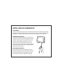
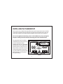
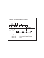
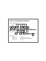
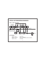
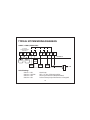
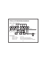
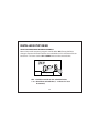
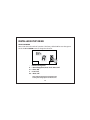
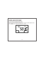
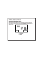
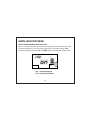
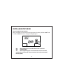
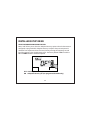
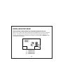
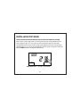
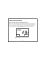
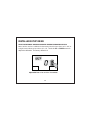
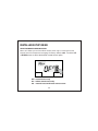
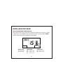
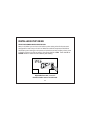
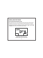
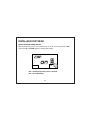
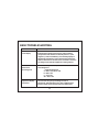
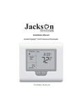
COMF RT SYSTEM™
T-32-TS Touchscreen Thermostat
Installation Manual
TABLE OF CONTENTS
Introduction
Getting Started
Installing The Thermostat
Disassembly
Thermostat Location
Mounting The Subbase
Terminal Designations
Setting The System Switches
System Switch Functions
Installing The Batteries
Typical System Wiring Diagrams
Heat Only (Gas)
Heat Only (Electric)
Cool Only
1 Heat / 1 Cool (Gas)
2 Heat / 2 Cool (Gas)
2 Heat / 1 Cool Heat Pump
3 Heat / 2 Cool Heat Pump
2 Heat / 1 Cool Fossil Fuel
3 Heat / 2 Cool Fossil Fuel
4
5
6
6
6
6, 7
8
9
10
11
12
12
13
14
15
16
17
18
19
20
1
TABLE OF CONTENTS
Installer Setup Menu
Entering The Setup Menu
Selecting The Program
Selecting Program Days
Selecting Temporary Program Override
Selecting Programmable Fan Mode
Selecting Mode
Selecting Touchscreen Lock Options
Selecting The Cooling Setpoint Limit
Selecting The Heating Setpoint Limit
Selecting The Temperature Display
Selecting The Time Format
Selecting The Setpoint Display Option
Selecting Back Light Option
Selecting Adaptive Recovery Option
Selecting Filter Reminder
Selecting First Stage Heating And Cooling Differential Option
Selecting Second Stage Heating And Cooling Differential Option
Selecting Third Stage Heating Differential Option
Selecting Internal Or Indoor Remote Sensor Calibration Option
Selecting Remote Sensor Option
Selecting Equipment Configuration
2
21
21
22
23
24
25
26
27
28
29
30
31
32
33
34
35
36
37
38
39
40
41
TABLE OF CONTENTS
Selecting Low Balance Point Option
Selecting High Balance Point Option
Selecting Audible Beep Option
Selecting The Factory Default Option
Selecting Daylight Savings Time Option
Remote Sensor Installation
Remote Sensors
Indoor Sensor Wiring
Using Multiple Sensors For Temperature Averaging
Outdoor Sensor Wiring
Temperature Calibration Chart
Testing
Testing Fan Operation
Testing Conventional Heating And Cooling Operation
Testing Conventional Heat Pump Operation
Testing Fossil Fuel Operation
Testing Low Balance Point (Heat Pump or Fossil Fuel)
Testing High Balance Point (Heat Pump or Fossil Fuel)
Adaptive Recovery
Basic Trouble Shooting
T-32-TS Specifications
3
42
43
44
45
46
47
47
47, 48
49
50
51
52
52
52, 53
53
53, 54
54
54, 55
55
56, 58
59
INTRODUCTION
The Comfort System™ T-32-TS is a feature-rich touchscreen thermostat that can be
battery powered or hardwired to the HVAC equipment. Using a common sense
approach to the installation will ensure this product is installed properly and to the
customer’s satisfaction. Please take time to read and understand this manual so that
installation and testing is performed in an efficient manner.
This manual is to be used in conjunction with the supplied User Manual.
Although great care has been taken in the preparation of this manual, Jackson
Systems takes no responsibility for errors or omissions contained herein. It is the
responsibility of the installer to ensure that this thermostat and the equipment
connected to it operate in a safe and efficient manner.
Due to ongoing product improvements, Jackson Systems reserves the right to change the
specifications of the T-32-TS thermostat or its components without notice.
All rights reserved.
©Jackson Systems, LLC 2012.
Intellectual rights apply.
4
GETTING STARTED
As with any HVAC project, careful installation is the key to a successful outcome. Tim
taken during the installation process will be rewarded with fewer call-backs.
The steps required to install the T-32-TS thermostat are as follows.
1. Read and understand this Installation Manual and User Manual
2. Mount and wire the subbase.
3. Install the batteries.
4. Set the 4 system switches to match the equipment application.
Heat / Cool
Heat Pump
Fossil Fuel
5. Wire optional remote temperature sensor(s).
6. Power the thermostat
7. Set the Advanced Installer settings.
8. Test the thermostat.
5
INSTALLING THE THERMOSTAT
DISASSEMBLY
There are two release slots located on the bottom of the thermostat. Gently push the
flat blade of a small screwdriver into one slot at a time and pry upward until the catch
disengages. Carefully swing the thermostat upward and away from the subbase.
THERMOSTAT LOCATION
The T-32-TS should be installed in a location that
represents the ambient space temperature. Do not
install the thermostat in an area where drafts are
present, near the floor, behind doors or on an
external wall. Avoid placing the thermostat in
areas where the air movement is limited, affected
by direct sunlight or other areas not typical of the
temperature in the space.
MOUNTING THE SUBBASE
When mounting the T-32-TS subbase, be aware
that drafts may travel down wall cavities and enter
the back of the thermostat through the control
wire hole in the wall. It is important to seal the
6
FIGURE 1
INSTALLING THE THERMOSTAT
hole to prevent any drafts that might affect the internal temperature sensor. Pull the
control wires through the large opening in the thermostat subbase. Next, level and
mount the subbase on the wall using the supplied anchors and screws. (Figure 2)
Do not over tighten the mounting screws as the subbase may warp causing the
improper seating of the thermostat connecting pins to the terminal blocks.
Use a properly sized screwdriver
and back each screw terminal out
(counter clockwise) before
landing each wire to its dedicated
terminal. Do not over tighten the
terminal screws. Check to ensure
that all wires are landed correctly
and dressed properly to prevent
any shorts. Refer to Typical System
Wiring Diagrams in this manual
for proper wiring.
Jackson Systems, LLC
BATTERY
COMPARTMENT
www.jacksonsystems.com
MOUNTING HOLES
W2
S2 SC S1 O/B W1
WIRE
ACCESS
HOLE
MOUNTING
HOLE
FIGURE 2
7
MOUNTING HOLES
Y1 Y2 G R C
INSTALLING THE THERMOSTAT
TERMINAL DESIGNATIONS
TERMINAL
S2
SC
S1
W2/OB
W1
Y1
Y2
G
R
C
DESIGNATION
Outdoor Sensor
Sensor Common
Indoor Sensor
Second Stage Heat or Reversing Valve
First Stage Heat / Auxiliary / Emergency Heat
First Stage Cool or First Stage Compressor
Second Stage Cool or Second Stage Compressor
Fan
24 VAC Hot
24 VAC Common
8
SETTING THE SYSTEM SWITCHES
The T-32-TS contains a set of four system switches located on the thermostat printed
circuit board. (Figure 3) The switches are used to match the thermostat operation and
relay outputs with the HVAC system requirements. Refer to the system switch
functions on the next page to properly configure the thermostat.
.....
FIGURE 3
9
1234
.....
ON
SYSTEM SWITCHES
SYSTEM SWITCH FUNCTIONS
Switch 1 - Equipment Type
Switch 1 sets the equipment type. For conventional heat /
cool equipment, set the switch to the OFF position
(factory default). For heat pump equipment set the
switch to the ON position.
Switch 2 - Fan or Reversing Valve
When Switch 1 is OFF
For Gas heat, set the switch to the OFF position (factory
default). For electric heat, set the switch to the ON
position.
When Switch 1 is ON
For ‘O’ reversing valve, set the switch to the OFF position
(factory default). For ‘B’ reversing valve, set the switch to
the ON position.
Switch 3 - Short Cycle Timer
For 4 minute short cycle protection, set switch to the
OFF position (factory default). To disable short
cycle protection, set switch to the ON position.
Switch 4 - Fossil Fuel Mode
For conventional heat pump equipment, leave
switch in the OFF position (factory default). For
fossil fuel equipment, set switch to the ON
position.
10
INSTALLING THE BATTERIES
The T-32-TS comes with two AAA batteries. Even if the thermostat is hardwired, battery
backup is recommended to maintain the real-time clock in the event of a power
failure. All other memory is non-voilatile in the event of battery or primary power loss.
Press in on the battery access compartment and slide the drawer out. Install the two
AAA batteries matching the + and - orientation. Push the battery compartment in until
it clicks shut. When the batteries are properly installed, the touchscreen display will
light up. (Figure 4)
+
FIGURE 4
11
TYPICAL SYSTEM WIRING DIAGRAMS
HEAT ONLY (GAS)
OPTIONAL
REMOTE SENSOR
TERMINALS
S2
SC
S1
W2
O/B
W1
Y1
Y2
G
R
C
THERMOSTAT
EQUIPMENT
OUTDOOR
SENSOR
INDOOR
SENSOR
HEAT 1
RELAY
Switch Settings
Switch 1 = OFF
Switch 2 = OFF
Switch 3 = OFF
Switch 4 = OFF
FAN 1
RELAY
24 V
Heat / Cool
Equipment controls fan on call for heat
Short Cycle Protection (No affect on setup)
Leave OFF
12
LINE
TYPICAL SYSTEM WIRING DIAGRAMS
HEAT ONLY (Electric)
OPTIONAL
REMOTE SENSOR
TERMINALS
S2
SC
S1
W2
O/B
W1
Y1
Y2
G
R
C
THERMOSTAT
EQUIPMENT
OUTDOOR
SENSOR
INDOOR
SENSOR
HEAT 1
RELAY
Switch Settings
Switch 1 = OFF
Switch 2 = ON
Switch 3 = OFF
Switch 4 = OFF
FAN 1
RELAY
24 V
Heat / Cool
Thermostat controls fan on call for heat
Short Cycle Protection (No affect on setup)
Leave OFF
13
LINE
TYPICAL SYSTEM WIRING DIAGRAMS
COOL ONLY
OPTIONAL
REMOTE SENSOR
TERMINALS
S2
SC
S1
W2
O/B
W1
Y1
Y2
G
R
C
THERMOSTAT
EQUIPMENT
OUTDOOR
SENSOR
INDOOR
SENSOR
COOL 1
RELAY
Switch Settings
Switch 1 = OFF
Switch 2 = OFF
Switch 3 = OFF
Switch 4 = OFF
FAN 1
RELAY
24 V
Heat / Cool
Fan energized on call for cooling
Short Cycle Protection (Recommended)
Leave OFF
14
LINE
TYPICAL SYSTEM WIRING DIAGRAMS
1 HEAT / 1 COOL (GAS)
OPTIONAL
REMOTE SENSOR
TERMINALS
S2
SC
S1
W2
O/B
W1
Y1
Y2
G
R
C
THERMOSTAT
EQUIPMENT
OUTDOOR
SENSOR
INDOOR
SENSOR
HEAT 1
RELAY
Switch Settings
Switch 1 = OFF
Switch 2 = OFF
Switch 3 = OFF
Switch 4 = OFF
COOL 1
RELAY
FAN 1
RELAY
24 V
Heat / Cool
Fan energized on call for cooling
Short Cycle Protection (Recommended)
Leave OFF
15
LINE
TYPICAL SYSTEM WIRING DIAGRAMS
2 HEAT / 2 COOL (GAS)
OPTIONAL
REMOTE SENSOR
TERMINALS
S2
SC
S1
W2
O/B
W1
Y1
Y2
G
R
C
THERMOSTAT
OUTDOOR
SENSOR
HEAT 1
RELAY
INDOOR
SENSOR
HEAT 2
RELAY
Switch Settings
Switch 1 = OFF
Switch 2 = OFF
Switch 3 = OFF
Switch 4 = OFF
COOL 2
RELAY
COOL 1
RELAY
FAN 1
RELAY
EQUIPMENT
24 V
Heat / Cool
Fan energized on call for cooling
Short Cycle Protection (Recommended)
Leave OFF
16
LINE
TYPICAL SYSTEM WIRING DIAGRAMS
2 HEAT / 1 COOL (HEAT PUMP)
OPTIONAL
REMOTE SENSOR
TERMINALS
S2
SC
S1
W2
O/B
W1
Y1
Y2
G
R
C
THERMOSTAT
OUTDOOR
SENSOR
EQUIPMENT
AUX
RELAY
INDOOR
SENSOR
REV
VALVE
Switch Settings
Switch 1 = ON
Switch 2 = OFF/ON
Switch 3 = OFF
Switch 4 = OFF
COMP
COOL 1
RELAY
FAN 1
RELAY
24 V
Heat Pump
OFF = ‘O’ ON = ‘B’
Short Cycle Protection (Recommended)
Leave OFF
17
LINE
TYPICAL SYSTEM WIRING DIAGRAMS
3 HEAT / 2 COOL (HEAT PUMP)
OPTIONAL
REMOTE SENSOR
TERMINALS
S2
SC
S1
W2
O/B
W1
Y1
Y2
G
R
C
THERMOSTAT
OUTDOOR
SENSOR
AUX
RELAY
INDOOR
SENSOR
REV
VALVE
Switch Settings
Switch 1 = ON
Switch 2 = OFF/ON
Switch 3 = OFF
Switch 4 = OFF
COMP 2
RELAY
COMP
COOL 1
RELAY
FAN 1
RELAY
EQUIPMENT
24 V
Heat Pump
OFF = ‘O’ ON = ‘B’
Short Cycle Protection (Recommended)
Leave OFF
18
LINE
TYPICAL SYSTEM WIRING DIAGRAMS
2 HEAT / 1 COOL (FOSSIL FUEL)
OPTIONAL
REMOTE SENSOR
TERMINALS
S2
SC
S1
W2
O/B
W1
Y1
Y2
G
R
C
THERMOSTAT
OUTDOOR
SENSOR
EQUIPMENT
AUX
RELAY
INDOOR
SENSOR
REV
VALVE
Switch Settings
Switch 1 = ON
Switch 2 = OFF/ON
Switch 3 = OFF
Switch 4 = ON
COMP
COOL 1
RELAY
FAN 1
RELAY
24 V
LINE
Heat Pump
OFF = ‘O’ ON = ‘B’ Reversing Valve
Short Cycle Protection (Recommended)
Locks out heat pump when furnace is energized
19
TYPICAL SYSTEM WIRING DIAGRAMS
3 HEAT / 2 COOL (FOSSIL FUEL)
OPTIONAL
REMOTE SENSOR
TERMINALS
S2
SC
S1
W2
O/B
W1
Y1
Y2
G
R
C
THERMOSTAT
OUTDOOR
SENSOR
AUX
RELAY
INDOOR
SENSOR
REV
VALVE
Switch Settings
Switch 1 = ON
Switch 2 = OFF/ON
Switch 3 = OFF
Switch 4 = ON
COMP 2
RELAY
COMP
COOL 1
RELAY
FAN 1
RELAY
EQUIPMENT
24 V
LINE
Heat Pump
OFF = ‘O’ ON = ‘B’ Reversing Valve
Short Cycle Protection (Recommended)
Locks out heat pump when furnace is energized
20
INSTALLER SETUP MENU
ENTERING THE SETUP MENU
Touch and hold both the Clock and Mode section for 5 seconds to enter the Installer
Menu.
E
AM
DST
E
01/01/2012
•
•
•
To advance through the menu, touch the Mode section.
To backup in the menu, touch the Fan section.
To exit the menu at any time and save changes, touch and hold the Mode
section until the display shows normal operation.
21
INSTALLER SETUP MENU
Back
Program
Morning Day
Evening Night
E
SELECTING THE PROGRAM
The first menu 1:PR selects programmable or non-programmable operation. Press the
UP or DOWN arrows to change the selection. The factory default is 4 (4 schedules per
day).
Next
0 = Manual Mode (non-programmable)
2 = 2 Schedules Per Day (Day / Night)
4 = 4 Schedules Per Day (Morning / Day / Evening / Night
22
INSTALLER SETUP MENU
E
SELECTING PROGRAM DAYS
If menu 1:PR is set to 2 or 4, 2:PD is used to select 5+2 programming or 7 day
programming. Touch the UP or DOWN arrows to change the selection. The factory
default is 7.
Back
Next
51 = 5+1+1 (Same schedule Mon-Fri and separate
schedules for Sat and Sun)
52 = 5 + 2 (Same schedule Mon-Fri and Sat-Sun)
7 = 7 (7 individual day programming)
23
INSTALLER SETUP MENU
Back
E
SELECTING TEMPORARY PROGRAM OVERRIDE
Menu 3:TH provides temporary program override. When OFF, (factory default) a
change in setpoint will remain until the next scheduled event or a fixed override can
be set from 1-12 hours. Use the UP or DOWN arrows to select override time.
Program
Next
OFF = Provides override to next scheduled event
1-12 = Override to selected time (1 - 12 hours in 1 hour
increments)
24
INSTALLER SETUP MENU
Back
E
SELECTING PROGRAMMABLE FAN MODE
Menu 4:PF is the Programmable Fan option which allows selecting continuous or auto
fan operation for each program event. The factory default is OFF. Use the UP or DOWN
arrows to select Programmable Fan.
Program
Next
ON = Programmable Fan
OFF = No Programmable Fan
Refer to the User Manual for selecting continuous or auto fan for each
scheduled event when the Programmable Fan option is ON.
25
INSTALLER SETUP MENU
E
SELECTING MODE
Menu 5:FN selects the mode of operation. The factory default is A for auto changeover.
Touch the UP or DOWN arrows to change the selection.
Next
Back
AUTO
- = Manual Changeover
A = Auto Changeover (Heat / Cool / Auto / Off
H = Heat / Off
C = Cool / Off
Ao = Auto / Off
Note: In Manual Changeover configuration the
heating and cooling setpoint can be the same.
26
INSTALLER SETUP MENU
E
SELECTING TOUCHSCREEN LOCK OPTIONS
Menu 6:LC allows you to prevent changes to all or part of the touchscreen functions.
The factory default is OFF. Touch the UP or DOWN arrows to change the selection.
Next
Back
OFF
1
2
3
4
5
= All functions unlocked
= Program locked
= Mode locked
= Fan locked
= UP / DOWN arrows locked
= Clock locked
6
7
8
9
27
= Fan / Mode locked
= Fan / Program / Mode locked
= Fan / Program / Mode / Clock
locked
= All functions locked
INSTALLER SETUP MENU
Set
E
SELECTING THE COOLING SETPOINT LIMIT
Menu 7:CL selects the minimum cooling setpoint. The factory default is 50. Touch the
UP or DOWN arrows to adjust the limit from 43° - 122°F.
Next
Back
28
INSTALLER SETUP MENU
Heat Set
E
SELECTING THE HEATING SETPOINT LIMIT
Menu 8:HL selects the maximum heating setpoint limit. The factory default is 90.
Touch the UP or DOWN arrows to adjust the limit from 41° - 120°F.
Next
Back
29
INSTALLER SETUP MENU
E
SELECTING THE TEMPERATURE DISPLAY
Menu 9:TD selects the temperature to be displayed in Fahrenheit or Celsius. The
factory default is F (Fahrenheit). Touch the UP or DOWN arrows to change the
display setting.
Next
Back
F = Fahrenheit
C = Celsius
30
INSTALLER SETUP MENU
E
SELECTING THE TIME FORMAT
Menu 10:CL selects the time format which can be 12 hour or 24 hour. The factory
deault is 12 (12 hour). Touch the UP or DOWN arrows to change the format.
Next
Back
12 = 12 Hour
24 = 24 Hour (Military Time)
31
INSTALLER SETUP MENU
Set
E
SELECTING THE SETPOINT DISPLAY OPTION
Menu 11:ST allows the option of continuously displaying the setpoint temperture with
the space temperature or only the sepoint temperature. The factory default is ON
(Setpoint Displayed). Touch the UP or DOWN arrows to change the display option.
Next
Back
ON = Setpoint displayed
OFF = No sepoint displayed
32
INSTALLER SETUP MENU
E
SELECTING BACK LIGHT OPTION
Menu 12:BL allows you to select the back light option. The factory default is ON. Touch
the UP or DOWN arrows to change the display option.
Next
Back
ON
= Back Light on for 10 seconds when screen is touched
OFF
= No Back Light
ALL
= Back Light on high for 10 seconds when screen is touched
and then low continuously. (Thermostat must be hardwired to 24VAC
for this option)
33
INSTALLER SETUP MENU
E
SELECTING ADAPTIVE RECOVERY OPTION
Menu 13:RC allows you to select the Adaptive Recovery option when the thermostat is
configured as programmable. Adaptive Recovery compares the space temperature
deviation from setpoint and rate of recovery history to bring the equipment on and
reach the setpont at the scheduled start time. The factory default is OFF. Touch the
UP or DOWN arrows to select this option.
Next
Back
OFF = No Adaptive Recovery
ON = Adaptive Recovery On (For programmable mode only)
34
INSTALLER SETUP MENU
E
SELECTING FILTER REMINDER
Menu 14:FT allows you to select a time when the thermostat will display FLT as a
reminder that the HVAC system filter(s) should be replaced. The factory default is OFF.
Touch the UP or DOWN arrows to set the filter reminder time.
Next
Back
OFF = No filter reminder
010 = 100 Hours
100 = 1000 Hours (Up to 9,000 hours in 100 hour steps)
To reset the Filter Reminder, touch and hold Mode and Fan.
35
INSTALLER SETUP MENU
E
SELECTING FIRST STAGE HEATING AND COOLING DIFFERENTIAL OPTION
Menu 15:S1 is used to adjust the heating and cooling differential. The factory default is
2 ( 2°F). This represents the temperature above the cooling setpoint or below the
heating setpoint when the equipment is energized. Touch the UP or DOWN arrows
to change the differential.
Next
Back
1 = 1°F Differential
2 = 2°F Differential
3 = 3°F Differential
36
INSTALLER SETUP MENU
E
SELECTING SECOND STAGE HEATING AND COOLING DIFFERENTIAL OPTION
Menu 16:S2 is used to adjust the second stage heating and cooling differential. The
factory default is 2 ( 2°F). This represents the temperature above the first stage
cooling differential or below the first stage heating differential when second stage is
energized. There is a 3 minute time delay before second stage is energized. Touch the
UP or DOWN arrows to change the differential.
Next
Back
Adjustable from 1 - 10°F in 1° increments
37
INSTALLER SETUP MENU
E
SELECTING THIRD STAGE HEATING DIFFERENTIAL OPTION
Menu 17:S3 is used to adjust the third stage heating differential. The factory default is
2 ( 2°F). This represents the temperature below the second stage heating differential
when third stage heat is energized. There is a 3 minute time delay before third stage
heat is energized. Touch the UP or DOWN arrows to change the differential.
Next
Back
Adjustable from 1 - 10°F in 1° increments
38
INSTALLER SETUP MENU
E
SELECTING INTERNAL OR INDOOR REMOTE SENSOR CALIBRATION OPTION
Menu 18:CA is used to re-calibrate the thermostat internal sensor when 19:TT = OFF, or
a single remote indoor sensor when 19:TT = RS . Touch the UP or DOWN arrows to
adjust the calibration. The factory default is 0.
Next
Back
Adjustable from -9° to +9°F in 1° increments
39
INSTALLER SETUP MENU
E
SELECTING REMOTE SENSOR OPTION
Menu 19:TT allows you to select indoor remote sensor only or remote sensor with
internal sensor for temperature averaging. The factory default is OFF. Touch the UP
or DOWN arrows to select the desired remote sensor option.
Next
Back
OFF = Internal sensor only
RS = Indoor remote sensor only
AU = Internal sensor with indoor remote sensor
40
INSTALLER SETUP MENU
E
SELECTING EQUIPMENT CONFIGURATION
Menu 20:R4 is used to select the specific equipment configuration. The factory default
is 1S for Heat / Cool and H2 for heat pump and fossil fuel. Touch the UP or DOWN
arrows to select the proper equipment configuration.
Next
Back
HEAT / COOL
HEAT PUMP
FOSSIL FUEL
1S = Single Stage
2S = Multi-stage
OFF = 1 Heat / 1 Cool
H2 = 2 Heat / 1 Cool
H3 = 3 Heat / 2 Cool
H2 = 2 Heat / 1 Cool
H3 = 3 Heat / 2 Cool
41
INSTALLER SETUP MENU
E
SELECTING LOW BALANCE POINT OPTION
Menu 21:LB allows you to select a low balance point setting when the thermostat is
configured for Heat Pump or Fossil Fuel. When the outdoor temperature falls below
the balance point setting, the compressor is locked out and only auxiliary electric heat
or fossil fuel furnace is used for heating. The factory default is OFF. Touch the UP or
DOWN arrows to select an low balance point setting.
Next
Back
Adjustable from OFF, 1° to 77°F
Remote outdoor sensor must be used
42
INSTALLER SETUP MENU
E
SELECTING HIGH BALANCE POINT OPTION
Menu 22:HB allows you to select a high balance point setting when the thermostat is
configured for Heat Pump or Fossil Fuel. When the outdoor temperature rises above
the balance point setting, the auxiliary electric heat or fossil fuel furnace is locked out
and only the heat pump is used for heating. The factory default is OFF. Touch the UP
or DOWN arrows to select an low balance point setting.
Next
Back
Adjustable from OFF, 32° to 122°F
Remote outdoor sensor must be used
43
INSTALLER SETUP MENU
E
SELECTING AUDIBLE BEEP OPTION
Menu 23:BP allows you to turn the audible beep on or off. The factory default is ON.
Touch the UP or DOWN arrows to change the setting.
Next
Back
ON = Audible beep when screen is touched
OFF = No audible beep
44
INSTALLER SETUP MENU
E
SELECTING THE FACTORY DEFAULT OPTION
Menu 24:RS can be used to reset the thermostat to the original factory defaults. The
factory default is OFF. To reset the thermostat, touch the UP or DOWN arrows and
set to ON.
Next
Back
OFF = Factory default disabled
ON = Factory default enabled
45
INSTALLER SETUP MENU
E
SELECTING DAYLIGHT SAVINGS TIME OPTION
Menu 25:DS is used to enable Daylight Savings Time for the real-time clock. The factory
default setting is ON. To disable this option, use the UP or DOWN arrows and set to
OFF.
Next
Back
ON = Daylight Saving Time
OFF = Daylight Saving Time disabled
Refer to User Manual to set Daylight Saving Time Calender
46
REMOTE SENSOR INSTALLATION
REMOTE SENSORS
There are two types of remote sensors. The T-32-S1 is a single sensor that can be used
indoors or outdoors. The T-32-S2 contains two sensors. A combination of both sensors
can be used for indoor temperature averaging with or without the onboard sensor.
Use separate 18-2 shielded cable when wiring sensors to prevent interference.
INDOOR SENSOR WIRING
When the T-32-S1 is used as an indoor sensor, the T-32-TS can be configured to allow
only the remote sensor to control the temperature or a combination of remote and
onboard sensors can be used for temperature averaging. Refer to 18:TT in the installer
setup menu to select the proper remote sensor option. The indoor sensor wires to
terminals S1 and SC.
S2 SC S1
FIGURE 5
T-32-S1
SENSOR
47
REMOTE SENSOR INSTALLATION
Locate the sensor in the same manner as the thermostat. Mount the sensor 18” away
from any outside wall. Do not install the sensor behind doors, in corners or other dead
air spaces. Keep the sensor away from direct air flow, supply registers or near sources
of heat such as lamps and appliances. The maximum wire length from the sensor to
the thermostat is 300 feet. Use a separate 18-2 shielded cable for sensor wiring. Prior to
wiring the sensor to the thermostat, use an ohm-meter or multi-meter to measure the
resistance of the sensor. Measure at the end of the wires that will connect to the
thermostat. Confirm the resistance value (within 5%) to the temperature where the
sensor is mounted. Use a quality digital electronic thermometer to read the
temperature at the sensor. Remove the sensor cover and place the thermometer probe
next to the sensor element to verify an accurate reading. Disconnect power to the
thermostat when wiring the sensor, strip only as much insulation off of the wires as
necessary to provide a good contact with the terminals. The sensor is not polarity
specific so either sensor lead may be connected to the SC or S1 terminals on the
thermostat.
48
REMOTE SENSOR INSTALLATION
USING MULTIPLE SENSORS FOR TEMPERATURE AVERAGING
Multiple indoor remote sensors can be wired in series/parallel for temperature
averaging. The total value of the sensors must equal 10KΩ @ 77° F. The onboard sensor
is not part of the equation even if it is configured as part of the averaging circuit.
However, when the onboard sensor is used with remote sensors, it represents 50% of
the averaging value. Figure 6 illustrates two T-32-S2 sensors used for averaging.
S2 SC S1
FIGURE 6
T-21-S2
SENSOR
49
T-21-S2
SENSOR
REMOTE SENSOR INSTALLATION
OUTDOOR SENSOR WIRING
When the T-32-S1 is used as an outdoor sensor, the T-32-TS thermostat will display the
outside air temperature as well as control high and low balance points for heat pump
and fossil fuel systems. Refer to 18:TT in the installer setup menu to select the proper
sensor option. The outdoor sensor wires to the SC and S2 terminals on the thermostat.
Figure 7 illustrates both an indoor and outdoor sensor configuration. Mount the
sensor on a vertical exterior surface below an overhang. Choose a location protected
from direct sunlight and exposure to excessive moisture. Follow the same wiring
procedures as installing an indoor sensor.
OUTDOOR SENSOR
S2 SC S1
T-32-S1
SENSOR
FIGURE 7
INDOOR SENSOR
T-32-S1
SENSOR
50
TEMPERATURE CALIBRATION CHART
Temperature
(°F)
Resistance
(KΩ)
Temperature
( F)
Resistance
(KΩ)
30
34.6
70
11.9
40
26.1
80
9.4
50
19.9
90
7.4
60
15.3
100
5.9
NTC type 2 sensor - 10KΩ @ 77° F
51
TESTING
The T-32-TS incorporates a short-cycle timer which can be disabled during testing by
setting slide switch 3 to the ON position. Once testing is completed, the time should
be enabled by setting the switch to OFF.
TESTING FAN OPERATION
Touch MODE until the word OFF is displayed. Touch FAN until the words Always On
appear. After a brief moment, the internal fan relay ‘G’ will energize and the system fan
should operate. Touch FAN again until the word Automatic appears. After a brief
moment, the internal fan relay will de-energize and the system fan will shut off.
TESTING CONVENTIONAL HEATING AND COOLING OPERATION
Touch MODE until the word Heat appears. Touch the UP arrow and raise the setpoint
above the space temperature and the first stage differential. After a brief moment, the
internal heating relay ‘W1’ will energize and the heating system should operate. The
word Heat will flash continuously. If the thermostat has been configured for two stage
heating, raise the setpoint above the second stage differential and the second stage
heating relay ‘W2’ will energize. The word Heat will flash twice, pause and repeat the
sequence to indicate second stage has been energized.
52
TESTING
Touch MODE until the word Cool appears. Touch the DOWN arrow and lower the
setpoint below the space temperature and the first stage cooling differential. After a
brief moment, the internal heating relay ‘Y1’ will energize and the cooling system
should operate. The word Cool will flash continuously. If the thermostat has been
configured for two stage cooling, lower the setpoint below the second stage
differential and the second stage cooling relay ‘Y2’ will energize. The word Cool will
flash twice, pause and repeat the sequence to indicate second stage has been
energized.
TESTING CONVENTIONAL HEAT PUMP OPERATION
When the T-32-TS is configured for conventional heat pump operation, testing is the
same as a heating and cooling system with the exception that the fan ‘G’ relay is always
energized with compressor, auxiliary and emergency heat calls.
TESTING FOSSIL FUEL OPERATION
When the T-32-TS is configured for fossil fuel operation, testing is the same as a
conventional heat pump system with the exception that the heat pump is never
allowed to run when the fossil fuel furnace is energized. Whenever the thermostat calls
for auxiliary heat, the compressor Y1 and/or Y2 relays are de-energized along with the
fan ‘G’ relay and the ‘W1’ relay will energize the fossil fuel furnace.
53
TESTING
With the installation of an outdoor sensor, both high and/or low balance point control
can be used to prioritize heat pump or fossil fuel operation based on a selected
outdoor temperature.
TESTING LOW BALANCE POINT (Heat Pump or Fossil Fuel)
When an outdoor sensor is used with the T-32-TS, Installer Option 21:LB allows you to
select a low balance point temperature. When the outdoor temperature falls below the
low balance point setting, the Y1 and/or Y2 compressor relays will be bypassed and
only the W1 (auxiliary heat) relay will be energized. To test the low balance point
setting, set 21:LB above the displayed outdoor temperature and force a call for
heating. The W1 relay will energize and the compressor Y1 and/or Y2 relays will be
bypassed. After testing, reset the low balance point temperature to a normal operating
range.
TESTING HIGH BALANCE POINT (Heat Pump or Fossil Fuel)
High balance point is designed to prevent the W1 (auxiliary heat) relay from energizing
when the outdoor temperature is above the balance point setting. To test the high
balance point setting, set 22:HB in the installer options menu below the displayed
outdoor temperature and force a call for heating by adjusting the thermostat setpoint
54
TESTING
above the first and/or second stage heating differential. The Y1 and/or Y2 compressor
relays will be energized and the W1 (auxiliary heat) relay will be bypassed. After
testing, reset the high balance point temperature to a normal operating range.
ADAPTIVE RECOVERY
Adaptive Recovery is only available in programmable mode (Installer Options Menu
13:RC = ON). The Adaptive Recovery function of the T-32-TS permits the user to
program a time that a desired set temperature is required. The thermostat then
calculates the most energy efficient time to energize the equipment to reach the
setpoint at the designated time. The calculation involves a complex control algorithm
that compares the space temperature deviation from setpoint and rate of recovery
history.
55
BASIC TROUBLE SHOOTING
SYMPTOM
POSSIBLE FAULT AND REMEDY
No LCD display
If thermostat is battery powered only, remove battery
compartment and check to see that the positive (+) and
negative (-) ends of each battery are oriented properly. If
thermostat is hardwired, remove the thermostat from the
subbase and check for 24 Volts across terminals ‘C’ and ‘R’. If
no voltage, fault could be equipment or wiring related.
Thermostat can
not be set for
auto changeover
In the Installer Options menu, set 5:FN=A or AO for
auto changeover.
- = Manual Changeover
A = Heat / Cool / Auto / Off
H = Heat / Off
C = Cool / Off
AO = Auto / Off
Temperature display
is inaccurate
Air from wall cavity may be leaking into rear of
thermostat. Seal hole where wires enter subbase. Move
lamps or other sources of heat away from thermostat.
56
BASIC TROUBLE SHOOTING
SYMPTOM
POSSIBLE FAULT AND REMEDY
Thermostat will not
display outdoor
temperature
No outdoor sensor installed. Check wiring at outdoor sensor
and sensor terminals on thermostat subbase. Outdoor
sensor wires to terminals S2 and SC.
Heat or Cool is flashing
This is not a fault but indicates that the thermostat heating
or cooling relay is energized.
Lock icon is displayed
when attempting to
set a higher or lower
setpoint
This is not a fault. The thermostat heating and cooling limits
may be preventing setting a temperature above or below
the limit values. These values can be changed in the Installer
Options menu.
7:CL (Cooling Limit) can be set from 43° - 122° F.
8:HL (Heating Limit) can be set from 41° - 120° F.
Touchscreen lock option 6:LC may be set to 4 which
prevents setpoint changes.
57
BASIC TROUBLE SHOOTING
SYMPTOM
POSSIBLE FAULT AND REMEDY
Thermostat displays
wrong temperature
The T-32-TS can be configured to display temperature in
either Fahrenheit or Celsius. Check Installer Option menu
9:TD. F = Fahrenheit and C = Celsius.
The fan continues to
run after a heating or
cooling call is satisfied
The thermostat fan mode may be set to Always On. Touch the
FAN icon and change it to Automatic. When the T-32-TS is
configured for programmable operation, fan operation can
be programmed for Automatic or Always On for any
scheduled event. If the Programmable Fan feature is not
required, set 4:PF in the Installer Option menu to OFF.
Some functions on the
thermostat cannot be
changed and a padlock
icon is displayed
Lock values have been set. Refer to 6:CL in the Installer Option
menu. To remove all lock values, set 6:CL = OFF.
58
T-32-TS SPECIFICATIONS
Input Voltage (Hardwired)
Relay Rating
Battery Power
Operating Temperature
Operating Humidity
Storage Temperature
Size:
Enclosure
LCD Display
Back Light
Short-cycle Delay
Displayed Temperature Resolution
Setpoint Ranges:
Heating
Cooling
Limits:
Heating (Factory default = 90° F)
Cooling (Factory default = 50° F)
Onboard and Remote Sensors
Resistance
Tolerance
Warranty
20-30 VAC 50/60 Hz
24 VAC @ 1 Amp maximum per relay
(2) AAA 1.5 V
32° F to 150° F
0-95% (non-condensing)
32° F to 150° F
5.0” W x 3.375” H x 1.0” D
3.75” W x 2.125” H
LED
Off or 3 minutes
1° F
41° F - 120° F
43° F - 122° F
Fully adjustable within heating setpoint range
Fully adjustable within cooling setpoint range
NTC Type 2
10KΩ @ 77° F
+/- 3% @ 77° F
5 Years
59
INDIANAPOLIS, IN 46203
www.jacksonsystems.com
06-1097-080212