1
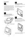
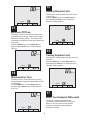
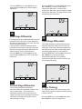
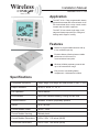
Wireless
COMF RT
Installation Manual
Model WCT-32
TM
Made in the USA
Application
The WCT-32 is a 7-day programmable, battery
powered thermostat that communicates via an
RF wireless data link to a relay control module
located near the HVAC equipment.
SYSTEM
The WCT-32 can control single stage, multistage and heat pumps with up to 3 stages of
heating and 2 stages of cooling.
FAN
Features
Manual or programmable selection with up
to four schedules per day.
Exclusive Memory Backup insures reliable
performance in the event of a
communications interruption.
Wireless 915MHz proprietary protocol with
up to 100’ transmission range.
Easy access, front-loading battery
compartment. 2 AA batteries included.
Specifications
Compatible Equipment
Single stage, multi-stage and heat pumps (3 heat / 2 cool)
Output Terminals
W1/B, O, W2/E, Y1, Y2, G
Fan Operation
Gas or electric
LED Indicator
Multi-color indicates heating, cooling and fan calls
Communications
Wireless, 915MHz, proprietary protocol
Range
Up to 100 feet
Control Module Power
24VAC, 2.4VA
Control Module Housing
Molded plastic
Control Module Dimensions
5.09 x 2.65 x 1.10 inches (WHD)
Thermostat Dimensions
5.00 x 4.50 x 1.00 inches (WHD)
2.65”
HVAC Module
.187” dia.
2 plcs
1
Installation
The HVAC module should be installed close to
the equipment being controlled. Do not install it
within a metal enclosure that might interfere with
wireless communications. Only standard 18
gauge thermostat wire is required to wire the
module to the equipment.
5.09”
4.57”
W1/B
O
W2/E
Y1
Y2
G
R
C
Two #6 sheet metal mounting screws are
included or the module can be installed with
double-backed adhesive tape.
2
1.10”
Wiring
The HVAC module is powered by the 24VAC
from HVAC system The diagrams below show
wiring when configured for Gas / Electric and
Heat Pump systems.
Gas / Electric (up to 2 heat / 2 cool)
Gas / Electric HVAC System
C
R
G
Y2
Y1
W2/E
O
W1/B
COM
R
G
Y2
Y1
W2
W1
Heat Pump (up to 3 heat / 2 cool)
Heat Pump System
COM
R
G
Y2
Y1
W2/E
O
B
C
R
G
Y2
Y1
W2/E
O
W1/B
2
Thermostat
5
3
Installing the Sub-Base
The thermostat should be installed approximately
5 feet above the floor.
Location
The thermostat should be located in an area that
represents the ambient space temperature and
within 100 feet of the HVAC Control Module. Do
not install the thermostat in an area where drafts
are present, near the floor, behind doors or on an
external wall. Avoid placing the thermsotat in
areas where the air movement is limited, affected
by direct sunlight or other areas not typical of the
temperature in the space.
Level the sub-base for appearance and use the
wall anchors and screws provided.
4
Removing the Sub-Base
Hold the sub-base with one hand, press the case
as shown below and pull the bottom of the
thermostat from the sub-base.
6
Installing the Batteries
Slide the battery cover off and install two AA
batteries included with the thermostat. Install the
batteries with the positive terminals to the right as
shown. Replace the battery cover.
Press here to release
case from sub-base.
The LCD will display the time of day, the setpoint
temperature and the room temperature.
3
Installer Options Chart
7
Option
Thermostat Installer Options
01
The installer options can be accessed by
pressing and holding the ENTER key for seven
seconds. The LCD displays Option 01 for setting
the Zone number. (See Installer Options Chart)
02
Press or hold the NEXT key to advance to the
next option. The LCD will advance through to
Option 16 and then return to Option 01.
04
03
05
Press the ENTER key to save all options in nonvolatile flash ram.
06
If only one wireless thermostat and HVAC Control
Module are used in an application, the thermostat
can be left with the factory default setting of Zone
= 01 and Home = 01.
07
08
If multiple wireless thermostats and HVAC
Control Modules are used that are less than 500
feet away from one another, each thermostat
must be set to a different Home number. For
convenience, set the Installer Options with the
thermostat off the subbase and in easy access of
its HVAC Control Module.
09
10
11
8
Setting the Zone Number
Use the Up and Down keys to set the Zone
number for the each thermostat. The Zone
number can be set from 01 to 08.
Description
Zone number
Range
01 to 08
01
Default
Home number
Range
01 to 32
Default
01
Program HVAC module with Zone
and Home address - Default 01
Equipment type
Range
00- G/E 01- Heat Pump
Default
00- G/E
Indoor Fan Operation
Range
00- Gas 01- Electric
Default
00- Gas
Minimum Off Time
Range
01 to 09 minutes
Default
00 minutes
Minimum Run Time
Range
01 to 09 minutes
00 minutes
Default
Maximum allowable heating setpoint
Range
60 to 85F
Default
85F
Minimum allowable cooling setpoint
Range
55 to 80F
65F
Default
Heat/Cool Setpoint Differential
Range
02 to 06F
02F
Default
Stage 1 Temperature Differential
Range
01 to 04F
01F
Default
12
Stage 2 Temperature Differential
Range
01 to 10F
03F
Default
13
Stage 3 Temperature Differential
Range
01 to 12F
05F
Default
14
Staging Time
Range
0 = OFF 1 = ON
Default
0
Staging Time When 14 = 1 (ON)
Range
15 - 30 (1 Minute Increments)
Default
15
15
Zone
16
Automatic Backup
Range
00- Off 01- On
01- On
Default
9
Setting the Home number
Option
CANCEL
NEXT
ENTER
Zone Numbers can be used to identify individual
thermostats. Press the NEXT key to advance to
the next option. Press the ENTER key if no more
options are to be changed.
Press the NEXT key to select Option 02. The
Home number is used to distinguish between
thermostats and HVAC Control Modules that are
less than 500 feet away from one another. This
could be a home with two HVAC systems or a
multi-family residence.
4
The LCD display for Option 03 is shown below.
Press the ENTER key to send the new address to
the HVAC module after pressing the module
program key and the LED starts to blink red and
green. When the module LED begins to flash
yellow, it will now only respond to the thermostat
with the same address. You will need to re-enter
the Installer Options menu to finish configuring the
thermostat.
Use the Up and Down keys to set the Home
number for the thermostat. The Home number
can be set from 01 to 32. Skip this option if no
other thermostats and modules are nearby.
Home
Zone
Option
CANCEL
NEXT
ENTER
10
Option
CANCEL
Programming the
HVAC Module
NEXT
ENTER
11
After selecting the Zone and Home numbers for
the thermostat, the same address must be
programmed into the HVAC Module. Power up
the module and press the program button. The
module will accept a new address for thirty
seconds. The LED on the module will alternately
blink red and green while it is waiting for a new
address after which the LED will display whatever
state the thermostat is in.
Selecting Equipment Type
The HVAC Control Module can be set for
either gas/electric or heat pump operation.
Press the NEXT key to select Option 04
and press the Up or Down key to select
00 = Gas/Electric or 01 = Heat Pump
operation.
Set To
Press Program Button
Option
CANCEL
NEXT
ENTER
12
Fan Operation
LED INDICATION
Press the NEXT key to select Option 05. The fan
can be set to 00 = Gas operation where the
equipment activates the HVAC system fan during
heating calls or to 01 = Electric operation where
the module activates the fan during heating calls.
In heat pumps and all cooling calls, the module
activates the fan (G) terminal.
Flashing Green - No calls
Solid Yellow - First stage cooling
Flashing Yellow - Second stage cooling
Solid Red - First stage heating
Flashing Red - Second stage heating
Solid Green - Fan
5
15
Set To
Heating Setpoint Limit
The maximum heating setpoint the user can set
is 60 to 85F.
Press the NEXT key to select Option 08 and
press the Up or Down key to set maximum
allowable heating setpoint.
Option
CANCEL
NEXT
ENTER
13
Set To
Minimum Off Time
The minimum Off time prevents the compressor
from restarting too quickly. Large HVAC systems
should use a longer Off time. The minimum Off
time and the minimum Run time also influence the
cycling rate.
Press the NEXT key to select Option 06 and
press the Up or Down key to set the Minimum
Off Time.
Option
CANCEL
NEXT
ENTER
16
Cooling Setpoint Limit
Set To
The minimum cooling setpoint the user can set is
55 to 80F.
Press the NEXT key to select Option 09 and
press the Up or Down key to set the minimum
allowable cooling setpoint.
Option
CANCEL
NEXT
ENTER
14
Set To
Minimum Run Time
The Minimum Run Time influences the cycling
rate and helps to evaporate condensation in heat
ex-changers.
Press the NEXT key to select Option 07 and
press the Up or Down key to set the Minimum
Run Time.
Option
CANCEL
NEXT
ENTER
17
Set To
Heat / Cool Setpoint Differential
The Heat/Cool temperature differential
prevents the heating setpoint from being set
above or too close to the cooling setpoint,
resulting in inadvertent cycling between
heating and cooling.
Option
CANCEL
NEXT
ENTER
6
Press the NEXT key to select Option 12 and the
Up or Down key to set the second stage
temperature differential. If the first stage
temperature differential is greater than third stage
temperature differential, first stage differential will
automatically be incremented.
Press the NEXT key to select Option 11 and
press the Up or Down key to set the setpoint
differential.
Set To
Set To
Option
CANCEL
NEXT
ENTER
Option
18
CANCEL
First Stage Differential
NEXT
ENTER
20
First stage temperature differential determines the
sensitivity of the thermostat. A lower differential
will cause the thermostat to cycle more often with
smaller temperature swings.
If the temperature differential between indoor
temperature and setpoint temperature is greater
than the first stage temperature differential, first
stage heating or cooling will be activated.
Press the NEXT key to select Option 11 and
press the Up or Down key to set the first stage
differential.
Third Stage Differential
Third stage temperature differential determines
when the equipment advances from second to
third stage. Setting the differential temperatures
the same for second stage and third stage turns
second and third stage on at the same time.
Press the NEXT key to select Option 13 and the
Up or Down key to set the third stage
temperature differential. The third stage
temperature differential cannot be set below the
second stage differential.
Set To
Set To
Option
CANCEL
NEXT
ENTER
Option
CANCEL
19
NEXT
ENTER
21
Second Stage Differential
Stage Timing
Second stage temperature differential
determines when the equipment advances from
first to second stage. If the temperature
differential between indoor temperature and
setpoint exceeds the second stage temperature
differential, the equipment activates second
stage heating or cooling.
The Staging Override Time will turn on the next
stage even though the temperature differential has
not been reached.
Press the NEXT key to select Option 14 and the
Up or Down key to set the stage timing.
7
comparing the temperature readings. Press and
hold the MENU key until the calibration screen
appears as shown. Use the Up and Down keys
to adjust the temperature calibration offset.
Press the ENTER key to save the setting and
return to normal thermostat operation.
Set To
Option
CANCEL
NEXT
ENTER
Inside
22
Automatic Backup
The HVAC Control Module saves the previous 24hour pattern of heating, cooling and fan calls in
memory. Should the module lose
communications with the thermostat because of a
low battery or other reason, the module
automatically repeats the call pattern of the
previous 24 hours.
MENU
CANCEL
NEXT
ENTER
Resetting Factory Defaults
To reset the factory defaults, remove the batteries
and re-install them while holding down the
SYSTEM key. All prior changes will default to the
factory settings. This will require resetting the
time of day and programming schedules if
necessary. Refer to the Installer Options Chart
default settings to make any additional changes.
Press the NEXT key to select Option 16 and the
Up or Down key to set the Backup On (01) or Off
(00). It is highly recommended that this option be
left on.
This installation manual should not be left
with unauthorized users as it contains
installer setup functions which, if not
correctly set, may cause damage to the HVAC
equipment or seriously affect performance.
Set To
This manual is to be used in conjunction with the
supplied User Manual.
Option
CANCEL
NEXT
Although great care has been taken in
preparation of this manual, Jackson Systems
takes no responsibility for errors or
omissions contained herein. It is the
responsibility of the installer to ensure that
this thermostat and the equipment connected
to it operate in a safe and efficient manner.
ENTER
23
Calibrating the Temperature
Sensor Offset
Due to ongoing product improvements, Jackson
Systems reserves the right to change the
specifications of the WCT-32 thermostat or its
components without notice.
Typically, it is not necessary to adjust the
temperature calibration offset from the factory
setting. If calibration is necessary, a high quality
electronic digital thermometer must be used. Place
the thermometer sensor probe next to the
thermostat sensor and allow five minutes before
All rights reserved.
© Jackson Systems, LLC 2010
Intellectual rights apply.
5418 Elmwood Avenue, Indianapolis, IN 46203-6025
Toll Free: 888.652.9663 Fax: 317.227.1034
www.jacksonsystems.com
8
06-1055-030211