1
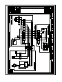
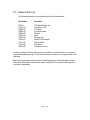
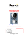
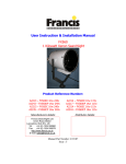
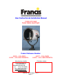
User Instruction & Installation Manual FH300 575 Watt Metal Halide Searchlight Product Reference Number: A2876 – 240v DECK A2878 – 240v DECK PEDESTAL Manufacturers details: A2877 – 240v CABIN A2879 – 240v CABIN PEDESTAL Distributor details: Francis Searchlights Ltd Union Road, Bolton Lancashire, BL2 2HJ, UK Tel: +44 (0) 1204 558960 Fax: +44 (0) 1204 558979 http://www.francis.co.uk E-mail: [email protected] Manual Part Number: C20377 Issue : 7 CONTENTS 1 - Introduction 2 - Safety Precautions 3 - Technical Information 4 - Unpacking and Installation Instructions 5 - Electrical Installation 6 - Operating Instructions 7 - Fault Finding 8 - Maintenance and Servicing 9 - Wiring Diagrams & General Assemblies 10 - Spare Parts List Back To Top 1 - Introduction It is imperative that this manual is read carefully and understood before installing your equipment. For your future reference please keep this manual in a safe place. Thank you for specifying a product from the Francis Searchlights range. All Francis products are designed to give complete customer satisfaction and are manufactured to the highest engineering standards in order to ensure optimum performance and service life. The Francis Metal Halide range combines features proven over many years service in the most hazardous conditions in both marine and land installations. In order to prolong the life and performance of your product, we recommend that you only specify Francis Searchlights spare parts. This will also ensure that any warranties on your equipment will not be invalidated. Information on spares ordering and parts is provided in this manual. Should you ever need to contact Francis Searchlights Ltd. regarding your equipment, please quote the Product Serial Number at all times. Back To Top 2 - Safety Precautions The following instructions must be adhered to, in order to ensure a safe working environment and the safety of the user. Note: When unpacking or manoeuvring the searchlight into its fixing position, suitable lifting points must be used in order to prevent damage to the equipment or personal injury. Because of the high internal pressure within the lamp, there is a risk of explosion in either a hot or cold state; During operation this lamp emits intense UV radiation which is harmful to the eyes and skin. Suitable protection should be worn; The high luminance of the arc can cause severe damage to the eye if viewed directly. ALWAYS wear suitable protective goggles when viewing the lamp; Always use protective sleeves supplied with the lamp; Should it be necessary to examine the lamp with the front bezel removed, always use a protective shield and wear goggles to ensure a safe working environment; Searchlights get hot. Never touch the unit when lit and always allow 15 to 20 minutes for cooling down after turning the searchlight off; Never place anything on or cover the searchlight when in use; Ensure the lamp has cooled sufficiently before removal; If undue force appears necessary to remove the lamp, the equipment should be inspected by a competent person or contact the manufacturer; When disposing of lamps, return the lamp, via the supplier, to the lamp manufacturer in its complete packaging; Due to the vast range of lamps available it may appear possible that more powerful lamps can be used in the equipment than for which it was designed. Even when the unit will physically accept a higher wattage or voltage lamp, this substitution is not recommended and is dangerous. This action will also void any warranties on the equipment. Always refer to the lamp manufacturers technical data when dealing with lamps. Back To Top 3 – Technical Information This product has been designed to operate in accordance with the product specification. The FH300 575 watt searchlight has the following features: All marine grade materials and fixings; Parabolic glass reflector; Stove enamel painted; Full 360° horizontal rotation; Vertical movement +45° to -25°; Remote focus facility (optional); Internal self-regulating heater.(Optional); Instant lamp re-strike. No cooling down time required; Economical 750 hour lamp life; Toughened front glass; Luminous flux 49000; Colour temperature 6000K; G.R.P. control gear protected to IP67; The searchlight also performs to the following optical data: Metal Halide light source G22; Lamp Wattage - 575 Watts; Supply voltage - 220/240V; Peak Beam Candlepower – 13,600,000 lux; Range – 3685 metres; Divergence – 2.5°; Temperature range: -50°C (with heaters fitted); In order that the searchlight operates correctly it is imperative that competent personnel are responsible for the installation, operation and servicing of this equipment. Failure to adhere to this advice may cause premature failure or incorrect operation of the searchlight, which may damage the equipment or cause personal injury. Back To Top 4 - Unpacking and Installation Instructions The following instructions should be read and fully understood prior to installing the equipment to ensure that the correct procedures are followed and all safety precautions are observed. Note: If the equipment has been in storage for a considerable amount of time, it is advisable to conduct a routine maintenance check on all parts before installation. Safety Precautions This equipment should not be connected to an electrical supply before being installed. Installation procedures should be adhered to in order to ensure a safe working environment and reduce the risk of damage or personal injury. Preparing the Mounting Position Mark out and drill the fixing holes through the deck. If anti-vibration mounts are to be fitted, the fixing holes for the mounts should also be marked out and drilled. Prior to manoeuvring the searchlight into its’ fixing position, the AV mounts should be fitted to the base. When in the desired position, bolt the searchlight firmly down. Back To Top 5 - Electrical Installation For safety purposes, only competent personnel should perform the electrical installation. All equipment should be installed to current Electrical Regulations and Standards. In order to obtain the maximum light output from the searchlight, it is essential that the full operating voltage of the lamp fitted be applied to the lampholder contacts. Method of Electrical Connection 1) Disconnect the supply before working on the electrical system; 2) The searchlight must be connected to a fused electrical supply, using suitably sized cable; 3) If the searchlight is located a considerable distance from the supply, provision must be made in the cable size in order to overcome the voltage drop. The Control Gear should NOT be positioned no more then 5 meters away from the Searchlight. The following table below indicates the maximum length of cable to be used for the AC supply cable, from the supply to the searchlight: Searchlight Cable Size (mm²) 1.5 2.5 4.0 6.0 10.0 240v 575w Distance Max 129 MTRS 210 MTRS 333 MTRS 520 MTRS 871 MTRS 4) Whenever possible cable terminations should be made below deck and with approved terminal devices; 5) If a spare auxiliary fuse or circuit breaker is not available, one of the correct type and rating should be fitted and connected to a positive supply. It is advisable to locate a bus bar or main connection and avoid any direct connection to the supply: 6) For 110/220v AC products, the following colour coding system should be used for the customer supply cable: Brown Blue Green/Yellow - Live - Negative - Earth Note: This equipment must be earthed. Installation Guideline A typical installation and connection routine for the FH300 searchlight is as follows: Referring to wiring diagram X4258, a supply is fed into the control gear enclosure, which then provides a common feed to the control gear and the searchlight. Cables required to be connected by the customer: 5 core 1.5mm cable from the Control Gear to the Searchlight, (Customer may need to provide a suitable junction box to this cable, 3 metres supplied). The Mains cable to the Control Gear is to be supplied by the customer. A typical installation and connection routine for the FH300 Remote Focus searchlight is as follows: Referring to wiring diagram C20294, a supply is fed into the control gear enclosure, which then provides a common feed to the control gear, control panel and searchlight. Cables required to be connected by the customer: 8 core 1.5mm cable from the Control Gear to the Searchlight 5 core 1.5mm cable from the Control Gear to the Control Panel. (Customer may need to provide a suitable junction box to extend these two cables, 3 metres supplied). The Mains cable to the Control Gear is to be supplied by the customer. Back To Top 6 - Operating Instructions This equipment is designed for use out of doors, in free air. Never place anything on, or cover, the searchlight when in use as this may present a hazard. The beam of the searchlight can be adjusted to give a variety of beam types. Using the lampholder focus wheel, the desired beam can be achieved for any particular application. On the Remote Focus model the beam of the searchlight can be adjusted to give a variety of beam types. Using the yellow remote focus button on the Control Unit, the desired beam can be achieved for any particular application. The beam will move continuously through ‘spot’ to ‘flood’. In order to fix the beam type; simply release the button at the desired position. Using the template provided mark out and drill the fixing holes through the deck or cabin roof. In case of cabin control models, a centre hole is also required to allow the mechanism to pass through. On an uneven surface when bolting down the searchlight it is necessary to use a suitable sealant, such as silicone, in order to ensure weather proofed joint. Please note that if a heater is fitted, it is advisable to leave the heater permanently in the ‘ON’ position in order to remove any condensation. The heater specified on this equipment is selfregulating and will shut off when the dew point temperature is reached. This product should not be used for any purpose other than for which it was designed. Any modifications to the product should not be undertaken without consulting the manufacturer. Setting to Work Safe service in use necessitates the strict observance of the following precautions. Any article fabricated from quartz or glass is inherently fragile and care should therefore be taken, at all times, when handling lamps; Eye protection must be worn when handling lamps that have been removed from their packaging materials. The protective sleeve should not be removed from the lamp for safety reasons, as there is a remote possibility of the lamp shattering violently, especially if it is subjected to mechanical shock or vibration; Ensure that the power rating of the lamp to be fitted is suitable for the lamphouse and power supply equipment; Always isolate the equipment from the supply before inserting a lamp; Before inserting the lamp ensure that all contacts are clean. Contacts must be renewed at the slightest sign of corrosion. Sanding or filing down corroded areas is not recommended as this will only make the conducting surface between the pin and lampholder smaller, thus causing the lamp to overheat; Do not twist or bend the fused quartz bulb when fitting the lamp as mechanical stresses MUST be avoided; When inserting or removing a lamp, always hold it securely by its’ base in order to prevent breakage between base and bulb; The lampholder must not exercise mechanical tensions on the lamp, neither during insertion or operation. Contacts must not discolour during use; For safety reasons, the lamp should be replaced once it has reached its’ average life, and not later than 1.25 times the stated life. With continuing use the risk of the lamp exploding increases due to alterations within the quartz; Before the protective sleeve is removed, suitable protection must be worn i.e face mask and gloves with wrist protection; Never touch the quartz bulb with bare hands, as fingerprints will make the glass cloudy and cause a severe loss of light. This may also cause recrystallisation and thus weaken the bulb material. Should the bulb be inadvertently touched, remove fingerprints with methylated spirit and a clean, soft paper towel. The bulb should then be wiped with distilled water. NOTE: ALWAYS WEAR MASK AND GLOVES DURING CLEANING); All packaging and the protective sleeve must be retained for re-use. Whenever removing a lamp, the protective sleeve must always be used for safety reasons; In all circumstances the lamp manufacturers data should be referred to when dealing with lamps. Back To Top 7- Fault Finding All fault finding must be conducted by a competent person or qualified Electrical Engineer. Failure of Lamp to ignite In the event of the lamp failing to light the following steps should be taken: 1) Check that the mains supply is connected to the input of the ballast gear and check all connections as per the wiring diagram. On operation if the lamp does not light, switch off mains supply and check all fuses; 2) Check the searchlight head. On your command get an operator to switch on the light for approximately 2 seconds. During this time listen for any noise (cracking or hissing) coming from within the barrel. If this arcing is heard switch off the supply at the mains. Remove the rear bezel to expose the two supply leads from the ignitor to the lamp. Using a dry cloth wipe these leads to remove any dust, moisture or condensation that may have formed around the inside of the barrel. Replace the rear bezel, ensure the latches are secure, and perform the check again, listening for the cracking. If the lamp still fails to ignite, switch off at the mains and replace the lamp in accordance with the safety procedures within the manual and the manufacturers information. Any further tests to be carried out with regards to lamp failure must be conducted by a competent electrical engineer and should not be carried out in an explosive atmosphere. 3) Before a metal halide lamp will ignite, the electrically insulated gas between the electrodes must be ionised. This is done by the ignitor which produces a high frequency voltage (up to 30,000 volts or higher). Switching the lamp on activates the ignitor. A cracking or hissing noise should be heard. The ignitor is housed within the rear of the searchlight barrel. If found to be faulty a new ignitor must be fitted. Failure of Remote Focus Facility (Optional facility) The remote focus mechanism is controlled by a small electric motor situated on the lampholder assembly within the searchlight barrel. If the focus of the light fails the following procedure should be adopted: 1) Remove the front bezel from the searchlight barrel and examine focus mechanism. If parts have become loose, tighten fasteners. The mechanism operates on a cam action and this should be checked for correct positioning; 2) If the mechanism is okay, check the supply to the motor. This can be done by simply placing a multimeter across the motor terminals; 3) If supply is present, this indicates that the motor has failed. Replace the focus motor ensuring that the assembly is correct; 4) If no supply is present, check the transformer in the control unit. Using a multimeter check the supply into and from the transformer. If found to be faulty, replace the transformer and check operation of focus mechanism. 5) If no supply is present there is a fault at the mains or the internal wiring of the control gear. This should be examined and rectified accordingly. Back To Top 8 - Maintenance and Servicing In order to prolong the service life and performance of your searchlight, the following maintenance guidelines are recommended: Maintenance checks should be conducted before every voyage or at least every three months; Before checking, disconnect the equipment from the supply; Visually inspect the condition of the equipment; Any major or minor structural damage should be rectified immediately in order to reduce sympathetic wear; After inspection it may be necessary to clean the inside of the searchlight. The following procedure should be adhered to: Remove the front bezel; Clean the front glass inside and out using a proprietary glass cleaner or metal polish; Clean the reflector if required; Check the reflector mounting gaskets. If signs of corrosion or damage are evident, replace as necessary; Ensure that the lampholder is free from corrosion or other damage; Check earthing point for conductivity; It is advisable to check all seals and gaskets for signs of degradation. Renew if necessary; Upon completing all maintenance requirements the searchlight should be tested for full working order (approximately 20 minutes). Every six months the external movement mechanisms i.e. lockwheels, elevation and pan mechanisms, should be lightly lubricated. If in any doubt as to the correct servicing procedures to adopt please contact your distributor/agent or the manufacturer who will be able to advise the best course of action for your product. Back To Top 9 - Wiring Diagrams & General Assemblies Drawing Number Description X4258 Wiring diagram (Manual focus) using ballast Parmar PPV575245 C20294 Wiring diagram (Remote focus) using ballast Parmar PPV575245 X4946 FH300 Deck X4947 FH300 Cabin X4948 FH300 Deck Pedestal X4949 FH300 Cabin Pedestal Remote Focus Control Unit 10 – Spare Parts List The following spare parts can be ordered directly from the manufacturer: Part Number Description D15764 C10870-00 C08890-00 C08891-00 C08884-00 C23338-00 C20070-00 C22268-01 C14143-00 C14142-00 C16488-00 575w Metal Halide Lamp Lampholder – G22 Front glass Front glass gasket Reflector Ignitor Drainage plug Breather Unit Assembly Selector Switch Push Button Transformer (Focus) In order to prolong the life and performance of your product, we recommend that you only specify Francis Searchlights spare parts. This will ensure that any warranties on your equipment will not be invalidated. When ordering spare parts please contact the Sales Department at Francis Searchlights Limited. Please quote searchlight model and serial number at all times. This will enable a fast response to your spares’ requirements. Back To Top