Transcript
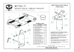
WT05134X01
(2) Accessory piping parts
MITSUBISHI ELECTRIC MULTI AIR CONDITIONERS OPTIONAL PARTS
CMY-Y100VBK2, Y200VBK2, Y300VBK2
Outdoor Twinning Kit Installation Manual
Supplied pipe
Section
Model
Liquid
OD12.7-ID9.52 (2)
OD15.88-ID12.7
OD22.2-ID19.05 (2)
CMY-Y100VBK2
Gas
OD22.2-ID28.58
Liquid
OD15.88-ID12.7 (2)
CMY-Y200VBK2
• For safe and correct use, please read this installation manual thoroughly before installation.
WARNING and
CAUTION symbols.
For your safety, follow the instructions with
Gas
OD34.93-ID41.28
Liquid
OD12.7-ID9.52
OD12.7-ID15.88 (2)
OD15.88-ID9.52
OD15.88-ID12.7
Gas
OD28.58-ID22.2 (3)
OD38.1-ID41.28 (1)
OD28.58-ID19.05 (2)
OD38.1-ID34.93
CMY-Y300VBK2
Safety Precautions
(3) Field supplied parts
• Before installing the unit, make sure you read all the “Safety precautions”.
• These precautions provide very important points regarding safety. Make sure you follow them.
• The following symbols are intended to alert the presence of danger in case of miss-operation.
WARNING
• Field supplied parts that do not come with the twinning kit
• Heat-resistant insulation material (for field piping)
• Insulation cover fixing tape
This symbol indicates that failure to follow the instructions exactly as stated poses the risk of serious injury or death.
This symbol indicates that failure to follow the instructions exactly as stated poses the risk of injury or damage to the
unit and other property.
CAUTION
2. Selecting the Size of the Refrigerant Pipe and How to Use the Twinning Kit
(1) PUHY-P500 – P900, EP400 – EP650
WARNING
Ask the dealer or an authorized technician to install
the unit.
Install the unit according to this Installation Manual.
• Select appropriate twinning types and sizes of connecting pipes.
If inappropriate types or sizes are connected, the air conditioning system cannot deliver the expected performance.
• Improper installation may result in problems such as gas
leakage.
Do not modify the unit in any way. Ask your dealer to
repair the air conditioner.
When installing or moving the unit, make sure that
the specified refrigerant (R410A only) is charged into
the refrigerant circuit.
• Improper installation by the user may result in water leakage,
electric shock, or fire.
Outdoor unit
unit 11
Outdoor
unit 22
Outdoor unit
(Outdoor unit × 2)
1 Prepare the pipe to be connected in the field.
2 Select the pipe size for each part from the table below. A (*)
mark after a pipe size indicates that the specified pipe size in
the following table can be obtained by connecting the accessory piping to the twinning kit.
3 Cut the pipe with a pipe cutter and remove the burr. Connect
the pipe after removing any dust or foreign matter.
• Any presence of foreign substance or even air can cause
abnormal pressure rise or explosion.
If refrigerant gas leaks during installation work,
ventilate the room.
After the installation is completed, make sure that the
refrigerant gas is not leaking.
• If the refrigerant gas comes into contact with a flame, poisonous
gases will be released.
c
d
ff
d
To
Indoor
To Indoor
unit unit
a
b
b
To Indoor
unitunit
To
Indoor
Gas twinning pipe
PUHY-P500 – P900
PUHY-P500
PUHY-P550
PUHY-P600
PUHY-P650
PUHY-P700
PUHY-P750
PUHY-P800
PUHY-P850
PUHY-P900
Unit 1
PUHY-P250
PUHY-P300
PUHY-P350
PUHY-P350
PUHY-P350
PUHY-P400
PUHY-P450
PUHY-P450
PUHY-P450
Unit 2
PUHY-P250
PUHY-P250
PUHY-P250
PUHY-P300
PUHY-P350
PUHY-P350
PUHY-P350
PUHY-P400
PUHY-P450
Set model
Set Unit
CAUTION
Twinning Type
Do not touch the refrigerant pipes during and
immediately after operation.
• Tear up and throw away any plastic packaging bags so that
children will not play with them. If children play with a plastic
bag which has not been torn apart, they run the risk of
suffocation.
a
Liquid twinning
pipe
Liquid
twinning
pipe
Gas twinning pipe
• If the refrigerant gas leaks into the room, and it is exposed to a
fan heater, space heater, kitchen range, or some other heat
source, it may generate a noxious gas.
Safely dispose of the packing materials.
ee
c
Indoor – Twinning
• During and immediately after the operation, the parts of the
refrigerant circuit including the refrigerant piping or the
compressor may be hot or cold, depending on the condition of
the flowing refrigerant. To prevent the risk of frostbite or burns,
do not touch these parts with bare hands.
CMY-Y200VBK2
CMY-Y100VBK2
Liquid
a
ø15.88
Gas
b
ø28.58
ø19.05
ø34.93
ø41.28 (*)
PUHY-EP400 – EP650
Set model
Set Unit
PUHY-EP400
PUHY-EP450
PUHY-EP500
PUHY-EP550
PUHY-EP600
Outdoor unit 1
PUHY-EP200
PUHY-P250
PUHY-EP300
PUHY-EP300
PUHY-EP300
PUHY-P350
Outdoor unit 2
PUHY-EP200
PUHY-EP200
PUHY-EP200
PUHY-P250
PUHY-EP300
PUHY-EP300
Outdoor Twinning Kit (optional parts)
* For general instructions on the installation of an outdoor unit, follow the Installation Manual for the outdoor unit.
1. Confirming the Supplied Parts
CMY-Y100VBK2
Indoor unit -
Liquid
a
ø15.88
Twinning pipe
Gas
b
ø28.58
Twinning kit
Twinning
kit
The twinning kit box (CMY-Y100VBK2, CMY-Y200VBK2, and CMY-Y300VBK2) contains the
following twinning and accessory piping parts. Make sure that the kit contains all of these
L-shape
pipe
d d(After
L-shape
pipe
(Afterthe
thetwinning)
twinning)
Insulation
Insulationcover
cover
parts.
Twinning
a
Twinning a
After checking, prepare the twinning kit by connecting the twinning pipes b, c, and d to the
twinning pipe a.
*Always use the twinning pipes included in the kit when preparing the twinning kit.
Depending on the model type, the size of the field piping may be different from the pipe size
b (Before
twinning)
Pipe c (After the twinning)
b (Before
the the
twinning)
of the twinning kit. In such a case, connect the following accessory piping parts to the kit. Pipe Pipe
Pipe c (After the twinning)
PUHY-EP650
Liquid
Gas
c or e
d or f
P250
ø9.52 (*)
ø22.2
P300
ø12.7
ø22.2
P350
ø12.7 (*)
ø28.58
P400
ø15.88
ø28.58
P450
ø15.88
ø28.58
EP200
ø9.52
ø19.05
EP300
ø12.7
ø22.2
Unit model
Twinning pipe - Outdoor unit
(1) Twinning pipes
Model
Section
Lebel
Twinning a
Liquid
A
15.88×12.7×12.7
Gas
D
28.58×25.4×25.4
Liquid
C
19.05×15.88×15.88
Pipe b (Before the twinning)
OD15.88-ID15.88
L83
OD28.58-ID28.58
L342
OD19.05-ID19.05
L85
OD31.75-ID34.93
L337
OD15.88-ID19.05
L85
OD19.05-ID19.05
L85
OD28.58-ID34.93
L337
OD31.75-ID38.1
L339
CMY-Y100VBK2
CMY-Y200VBK2
CMY-Y300VBK2
Gas
B
31.75×28.58×28.58
Liquid
Second row
A (Red)
15.88×12.7×12.7
Liquid
First row
C (Red)
19.05×15.88×15.88
Gas
Second row
D (Red)
28.58×25.4×25.4
Gas
First row
B (Red)
31.75×28.58×28.58
Pipe c (After the twinning)
OD12.7-ID12.7
L128
OD25.4-ID22.2
L190
OD15.88-ID15.88
L123
OD28.58-ID28.58
L192
OD12.7-ID12.7
L128
OD15.88-ID19.05
L125
OD25.4-ID28.58
L192
OD28.58-ID34.93
L187
L-shape pipe d (After the twinning)
Insulation cover
OD12.7-ID12.7
Small
OD25.4-ID22.2
Large
OD15.88-ID15.88
Small
OD28.58-ID28.58
Large
OD12.7-ID12.7
Small
OD15.88-ID15.88
Small
OD25.4-ID28.58
Large
OD28.58-ID28.58
Large
Instruction
(2) PUHY-P950 – P1250, EP700 – EP900
Outdoor
unit11
Outdoor unit
Outdoorunit
unit2 2
Outdoor
1
(This sheet)
gg
ee
hh
PUHY-P950 – P1250
d
pipe
jj
aa
ToIndoor
Indoor
To
unit
unit
Liquid
2 twinning
Liquid
2 twinning
pipe pipe
b
To Indoor unit
b
To Indoor unit
Gas
2 twinning
pipe
Gas
2 twinning
pipe
2
3. Example of a Pipe Connection
Set model
Unit 1
PUHY-P950
PUHY-P1000
PUHY-P1050
PUHY-P1100
PUHY-P1150
PUHY-P1200
PUHY-P1250
PUHY-P400
PUHY-P400
PUHY-P400
PUHY-P400
PUHY-P450
PUHY-P450
PUHY-P450
Unit 2
PUHY-P300
PUHY-P300
PUHY-P350
PUHY-P350
PUHY-P350
PUHY-P400
PUHY-P450
Unit 3
PUHY-P250
PUHY-P300
PUHY-P300
PUHY-P350
PUHY-P350
PUHY-P350
PUHY-P350
See the following drawing for connecting the pipes between the outdoor units.
<For 2 outdoor units>
CMY-Y300VBK2
Twinning Type
Twinning 1 – Twinning 2
ii
c
Liquid 1 twinning pipe
pipe
d
GasGas
1 twinning
pipe
1 twinning
1
Indoor – Twinning 2
c
Liquid 1 twinning
ff
Set Unit
Outdoor
unit33
Outdoor unit
(Outdoor unit × 3)
1 Prepare the pipe to be connected in the field.
2 Select the pipe size for each part from the
table below. A (*) mark after a pipe size
indicates that the specified pipe size in the
following table can be obtained by connecting
the accessory piping to the twinning kit.
3 Cut the pipe with a pipe cutter and remove the
burr. Connect the pipe after removing any dust
or foreign matter.
Liquid
a
ø19.05
Gas
b
ø41.28 (*)
Liquid
c
ø19.05
Gas
d
ø34.93
PUHY-EP700 – EP900
Set model
Set Unit
PUHY-EP700
PUHY-EP750
PUHY-EP800
PUHY-EP850
PUHY-EP900
Unit 1
PUHY-EP300
PUHY-EP300
PUHY-EP300
PUHY-EP300
PUHY-EP300
Unit 2
PUHY-EP200
PUHY-P250
PUHY-EP300
PUHY-EP300
PUHY-EP300
Unit 3
PUHY-EP200
PUHY-EP200
PUHY-EP200
PUHY-P250
PUHY-EP300
Outdoor Twinning Kit (optional parts)
Fieldpiping
piping
Field
Twinning
Twinning kit
kit
CMY-Y300VBK2
Indoor unit -
Liquid
a
Twinning pipe 2
Gas
b
Twinning pipe 1 –
Liquid
c
ø19.05
Twinning pipe 2
Gas
d
ø34.93
Fieldpiping
piping
Field
ø19.05
Liquid
Gas
e or g or i
f or h or j
P250
ø9.52 (*)
ø22.2
P300
ø12.7
ø22.2
P350
ø12.7 (*)
ø28.58
P400
ø15.88
ø28.58
P450
ø15.88
ø28.58
EP200
ø9.52
ø19.05
EP300
ø12.7
ø22.2
Unit model
Twinning pipe - Outdoor unit
The length of the straight pipe must
The500
length
straight
pipe must be
be
mm of
(19the
inch)
or longer.
500 mm (19 inch) or longer.
ø41.28
ø34.93
<For 3 outdoor units>
Field
Field piping
piping
(3) The angle of tilt of the twinning pipe
The angle of tilt of the twinning pipe should be within ±15° with the
ground.
Tilting the twinning pipe more than specified will cause damage to the
unit.
Twinning
Twinning kit
kit
Field
piping
Field
piping
Twinning kit
Twinning kit
The length
of theof
straight
pipe must
The length
the straight
pipe must
be 500bemm
(19 inch) or longer.
500 mm (19 inch) or longer.
Note: See the following drawing for the fitting position
Note: See
the
following
of the
twinning
pipe.drawing for the fitting position
of the twinning pipe.
Fieldpiping
piping
Field
Reducer
Reducer
The length of the straight pipe must
be
500
mm (19
inch)
or longer.
The
length
of the
straight
pipe must
be 500 mm (19 inch) or longer.
For the twinning kit, always use the accessory piping parts. The length
of the straight part of pipe connected in front of the twinning pipe must
be 500 mm (19 inch) or longer. (Connect the field piping so that the
length of the straight part of pipe connected in front of the twinning pipe
can be 500 mm (19 inch) or longer.)
If the length is less than 500 mm (19 inch), it will cause damage to the
unit.
±15°
±15°
(4) The length of the straight part of the pipe before the twinning
The angle of tilt of the reducer should be within
4. Installing the Insulation Cover
The angle of tilt of the reducer should be within
±15° with the ground.
±15° with the ground.
After brazing the pipes and the twinning kit, insulate the twinning kit with the insulation cover.
Add insulation materials on all the refrigerant piping, including the field piping. Make sure to insulate the pipes for liquid and gas
separately. When using commercially available insulation material, make sure to use heat-resistant insulation material with heatresistant temperature of 120 °C or higher.
Align the edges of the insulation cover and the heat-resistant insulation material so that there will be no gap. Seal also the periphery
and centre of the twinning part with a tape (field supply).
(5) The piping connection
When connecting the twinning kit to the outdoor unit, note the following:
· If the length of piping from the twinning kit to the outdoor unit is more than 2 m (6 ft), install a trap within 2 m (6 ft) from
the outdoor unit.
The height of the trap must be 200 mm (7 inch) or higher.
<2 m (6 ft) or less>
Insulation
material
supply)
Insulation
material
(field(field
supply)
Field
piping
Field
piping
<More than 2 m (6 ft)>
Field piping
Field
piping
Twinning kit
Twinning
kit
200
inch)
200mm
mm (7
(7 inch)
or or
over
over
To
ToIndoor
Indoorunit
unit
Insulation
Insulationcover
cover
· When installing the twinning kit in a higher
position than the outdoor unit base, make sure
that the twinning kit is installed in a position
lower than 200 mm (7 inch) from the outdoor
unit base.
Outdoorunit
unit1 1
Outoor
Outdoor
unit22
Outoor unit
Outdoor
unit3 3
Outoor unit
Insulation
cover
Insulation cover
Insulation
material
Insulation material
(field
supply)
(field supply)
Lapped
space
of taping
Lapped
space
of taping
Twinning
1
Twinning 1
Twinning
Twinning 22
Tape (field
(field supply)
Tape
supply)
To
unit
ToIndoor
Indoor
Less than
200 mm (7 inch)
Less than
200 mm
(7 inch)
As the insulation cover
contracts slightly, conduct
The insulation
coversecurely by
taping
in the field
shrinks slightly,
so parts
wrap the
providing
lapped
as
insulation cover and the
shown
in the left, so that no gap
field-installed insulation
will
exist on the insulation cover
material securely with tape
and
field supply
by overlapping
theinsulation
tape as
material.
shown left.
Tape (field
(field supply)
supply)
Tape
Tape
(field
supply)
Tape
(field
supply)
unit
3
Page 1
Insulation material
material
Insulation
(field supply)
supply)
(field
Less
Less than
than
2
2m
m (6
(6ft)
ft)
m(6
(6ft)ft)
22 m
WT05134X01_A2_P65
Fieldpiping
piping
Field
To
ToIndoor
Indoorunit
unit
4
07.4.25, 9:17 AM
Adobe PageMaker 6.5J/PPC