1
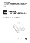
Installation Manual
Low Profile Air
Excellent System
Table of contents
Design
Serial production design
Composition of the air distribution system
Components
Air distributor
Distribution manifold components
Sealing ring
Orifice plate
Air distribution pipe
Snap connector
Pipe cap
Vertical bend 90°
Horizontal bend 90°
Connection for valve Ø125
Connection part of the floor grille
Supply air valve 125 mm
Exhaust air valve 125 mm
Floor grille 350 X 130 mm
1
1.1
1.2
1.3
1.3.1
1.3.2
1.3.3
1.3.4
1.3.5
1.3.6
1.3.7
1.3.8
1.3.9
1.3.10
1.3.11
1.3.12
1.3.13
1.3.14
1
1
2
3
4
4
5
5
5
5
6
6
6
6
7
7
7
7
Installation of the air delivery system
General
Installation of air distributor pipes to air distributor
Bends in air distribution system
Assembly of the floor grille or the supply / exhaust air valve
Change position of the air distribution pipe
Attention emphasis points on the connection of the pipe system
Air distributor
2
2
2.1
2.2
2.3
2.4
2.5
2.6
8
8
8
10
10
11
11
12
Pressure loss
Pressure loss low profile duct system – Air Excellent
3
3.1
13
13
Service
Service parts
4
4.1
14
14
Flat profile duct system Excellent
Design
1.1 Serial production design
The green plastic air distribution system is a newly
designed product by Brink Climate Systems which
is specifically intended for balanced ventilation,
demand controlled ventilation or air conditioning
with heat recovery. It is a modular system, which
is composed of a flat channel, several accessories
and an air distribution cabinet. The serrated flat
canal is delivered in the size 50 x 100 mm and is
suitable for an air volume flow rate of 30 – 35 m3
h with a flow velocity of about 3 m/s.
The flat channel can be processed easily and
connected without special tools to the auxiliary
components. The flat channel can be easily cut to
length with a saw.
The plastic parts used are antistatic and
antibacterial.
A program is made available by Brink, with which
the values of orifice plates (number of rings which
must be snipped off ) can be determined in an
easy way. A post facto adjustment of the orifice
plates is time consuming, since the pipes must be
decoupled once again for this. The orifice plates
may only be fixed on the distribution cabinet
connectors and not on the auxiliary parts.
An example which shows how all this functions is
given in the calculating program.
These assembly instructions shall not go into the
function of the calculation program any further.
The flat channel and the accessories are supplied
exclusively in green colour; exceptions are the seal
rings and the air flux flow regulator, these are
coloured red.
Low profile duct system Excellent
1
Design
1.2 Composition of the air distribution system
2
Low profile duct system Excellent
Design
A
Brink Renovent
Brink heat recovery unit type Renovent
B
Fresh air distributor
Distribution cabinet, to which all air feed channels are coupled, see § 1.3.1
C
Exhaust air distributor
Distribution cabinet, to which all air exhaust channels are coupled, see § 1.3.1
D
Thermally insulated EPE pipe system
The thermally insulated EPE pipe system is used to connect the ceiling /
roof or façade primary ducts to atmosphere and the air distributor to the
Renovent HR. The use of this EPE pipe prevents the formation of condensate.
E
Exhaust / (fresh) air roof cowl
The ventilation air exhaust through the roof / ceiling. For fixing and / or the
dimensions see the installation instructions sent regarding Renovent
F
Fresh air supply through the
façade cowl
The inner side – insulated façade cowl, through which the clean exterior air
is drawn in. For the fixing and / or the dimensions see the installation
instructions sent regarding Renovent.
G
Flat low profile duct
The flat low profile air delivery piping in the size 50 X 100 mm,
see section § 1.3.5
H
Distribution box connectors
The distribution manifold connectors are used for the connections of the
air channels; a distribution manifold has 5, 10 or 15 distribution box
connectors, see section § 1.3.2.
I
Orifice plate
The orifice plates are fixed in the distribution manifold at the assembled
seal ring of the air distributor pipe which is ; by cutting through a ring or
several rings, the air through flow can be adjusted, see section § 1.3.4.
J
Sealing ring
The sealing ring enables a good, air tight seal between the air distribution
pipe and the other components of the air distribution system,
see section § 1.3.3.
K
Duct cap
The duct cap is used for closing the connectors in the distributor manifold
or in the floor gratings which are not being used, section § 1.4.7
L
90° vertical bend
The vertical bend is used to guide an air distributor pipe towards the top
or the bottom, see section § 1.3.8.
M
90° horizontal bend
The horizontal bend is used to guide an air distributor pipe towards the
right or the left, see section § 1.3.8.
N
Snap connector
Two plastic air distributor pipes cab be connected to each other with a
snap connector, see section § 1.3.6.
O
Connection part for valve
With an angle connection part, a supply air or exhaust air valve can be
connected to the air distribution system, see section § 1.3.10.
P
Connection part floor grille
With a floor grille connection part, a floor grille can be connected to the
air distribution system, see section § 1.3.11.
Q
Floor grille 350 X 130 mm
Floor grille; can be supplied in stainless steel or white epoxy coated, see
section § 1.3.14
R
White PVC supply air valve Ø125
Through this white PVC supply air valve, fresh filtered air is supplied to the
room, see section § 1.4.12.
S
White PVC exhaust air valve Ø125
Through this white PVC exhaust air valve, stale or contaminated air is
extracted from the room, see section § 01.03.13.
T
Sealing duct dust cap to suit
floor grille.
For each connection part of the floor grilles, one right angled duct dust
cap is also supplied; this remains fitted on during the installation so that
the air ducts do not get contaminated. Only when all construction work is
completed is the floor grille fitted.
U
Sealing dust cap connection
to suit valve Ø 125 mm
For each connection part of the floor gratings, one round pipe sealing cap
Ø 125 mm is also supplied; this remains fitted on during the installation
so that the air ducts do not get contaminated. Only when all construction
work is completed, is the corresponding valve fixed.
Low profile duct system Excellent
3
Design
1.3 Components
1.3.1 Air distributor (Manifold)
The air distributor is identical for both the supply air and the
exhaust air. This air distributor is available in three models
depending on the number of the air connectors required, that is
with 5, 10 and 15 connections respectively. The connection
diameter also varies with the model. The air distributors are
manufactured from 1 mm zinc plated steel sheet and are insulated
to minimise noise pollution.
Design
Connector diameter
5 connectors
10 connectors
15 connectors
Ø 125 mm holes
Ø 150 mm holes
Ø 180 mm holes
By exchanging the plate, on which the air distributor manifold
connectors are fixed as well as the sealing cap of the air
distributors, the arrangement of the air distributor can be adapted
to the layout conditions on site, see section § 2.6.
An assembly kit is also included for the wall assembly, which
among other things has four angle brackets; these can be screwed
in a secure manner depending on the layout at the air distributor.
The air distributor can be fixed to the wall
For dimensions of the air distributor see section § 2.6
1.3.2 Distributor manifold connectors
At each air distributor connector there is a distributor manifold
connector, to which an air pipe can be connected. Thus at an air
distributor with 15 connectors, 15 distributor manifold connectors
are assembled in the factory.
The distributor manifold connectors rest in the openings of the air
distributor which are meant for them and are subsequently screwed
tight.
If it is necessary to loosen an air distributor connector, this is
possible by first removing the securing screw and lifting the
corresponding distributor connector somewhat and thereupon
pulling the distributor connector towards the front out of the
opening of the distributor manifold. While fixing the distributor
connector, it is to be pushed in and fixed down; subsequently it is
to be screwed tight again.
For dimensions of the air distributor see section § 2.6
4
Low profile duct system Excellent
C
Design
1.3.3 Sealing ring
In order to obtain an airtight seal between an air distributor
manifold pipe and an air distributor or another component of the
air distribution system, a sealing ring must be affixed at all
places where an air distributor pipe is connected.
This sealing ring is first assembled on the air distributor
connector and subsequently in the air distributor (if necessary
provided with an orifice plate) or plugged into another
component of the air distributor system. The assembly of this
sealing ring in the air distributor pipe is only possible in one way
(see for this section § 2.1); an air pipe with a sealing ring
assembled can indeed be assembled rotated (see section § 2.4).
1.3.4 Orifice plate
An orifice plate can be used in order to adjust the air quantity to
a valve or a grille. This is clamped to the sealing ring and
subsequently pushed in together with the air distributor pipe in
the air distributor manifold connector (see also section § 2.1).
The orifice plate is provided with 4 blowout rings; the higher the
number of rings that are cut out, the greater the air quantity
which is supplied to the grating or valve.
With the help of the Brink calculation program, it can be
determined as to how much air must be supplied to each
particular grille or valve and how many rings must be cut out
from the orifice plate.
1.3.5 Air distribution pipe
With the flexible flat channel, the aeration air is forwarded from
the air distributor onwards up to the grille or the valves as
applicable. The flat sided pipe with the dimensions 50 x 100 mm
is suitable for an air volume flux if 30 - 35 m3/h with a velocity
of 3 m/s.
If more air is to be forwarded to a grille or valve, 2 adjacent
pipes must be led to the grille or valve; the angle connection
part of the floor grating or the connection of to the grille or valve
is already fitted with a double barrel air connector (see also
section §1.3.10 / section §1.3.11).
The air distributor pipe must always be fitted with the flat side
to the wall or floor board as the case may be.
100
1.3.6 Snap connector
A snap connector can be supplied for joining two air distributor
pipes.
The flexible air pipe (including sealing rings) can be used on
both sides of the flexible air pipe.
Low profile duct system Excellent
5
Design
1.3.7 Duct caps
The openings on the distributor manifold connectors (or angle
connection parts of the floor grille) onto which no air distribution
pipe are connected are to be closed with a duct cap (see also
section §2.1).
While attaching the duct cap, no sealing ring needs to be fixed.
1.3.8 Vertical bend 90°
While the flexible air distribution pipe can be bent vertically, but
due to the large radius which arises from this, it is recommended
to use a vertical bend 90° for the purpose instead.
A flexible air pipe (including sealing rings) can be connected on
both sides of this arc (see section §2.2).
1.3.9 Horizontal bend 90°
The flexible air distribution pipe can be bent horizontally only very
slightly; a horizontal bend 90° is to be used for this. A flexible air
pipe (including sealing rings) can be connected on both sides of
this arc (see section §2.2).
1.3.10 Connecting part for valve Ø125
This connecting part can be supplied in order to connect valves
with a connection diameter of Ø125 mm. If the air volume coming
out of the concerned valve is less than 30 m3/h, a single air pipe
connector is sufficient; the other connector is to be closed with a
duct cap in this case (see section §1.3.7). If the air volume coming
out of the valve is between 30 and 60 m3/h, a second flexible air
pipe must be connected to the connecting part. This connecting
part for the valve is provided with a duct cap and is delivered
mounted on one of the connectors.
If there is not enough space for the connecting part for valves,
then it is possible to cut the round duct of Ø 125 diameter with the
help of a saw. For the cut to be right-angled, (perpendicular to the
pipe axis) auxiliary markings are provided on the whole length of
the shaft.
See section §2.3 for an example of assembly
This connecting part for valves is supplied together with an
assembled round duct cap 125 mm diameter. This cap is not to be
removed during the installation period (if the shaft is cut to size,
the cap is to be fixed anew). The valve desired is to be fixed only
after completion of the construction work.
6
Low profile duct system Excellent
Design
1.3.11 Connecting part of the floor grille
This connecting part can be supplied in order to connect the
floor grille with the dimensions 350 X 130 mm (see section
§1.3.14) to the air distribution system. If the air volume coming
out of the concerned grille is less than 30 m3/h, a single air pipe
connector is sufficient; the other connector is to be closed with a
duct cap in this case (see section §1.3.7). If the air volume
coming out of the grille is between 30 and 60 m3/h, a second
flexible air pipe must be connected to the connecting part. This
connecting part for floor grille is provided with a duct cap and is
delivered mounted on one of the connectors.
If there is not enough space for the floor grille connecting part,
then it is possible to cut the rectangular shaft to size with the
help of a saw. In order that the cuts are right-angled, auxiliary
markings are provided on the whole length of the shaft. The
connecting part is provided with a flange on the reverse side,
with which the connecting part can be affixed.
The desired grille is to be fixed only after completion of
the construction work.
This connecting part is supplied along with an assembled duct
cap. This cap is not to be removed during the installation period
(if the shaft is cut to size, the cap is to be fixed anew).
1.3.12 Supply air valve 125 mm
The highly induction white PVC air delivery valve (colour
RAL9016) is provided with an up stand or mounting curb so that
dirtying o the wall or ceiling is avoided.
A strip for a clean zone is delivered with this valve. The valve is
provided with three stainless steel clamp springs and a rubber
fixing ring for easy assembly. The supply air valve can be
adjusted continuously (no steps – adjusting screw reached after
detaching a round cap on the front side of the valve).
1.3.13 Exhaust air valve 125 mm
The white PVC exhaust air valve (colour RAL 9016) is especially
suitable for humid enclosures. The valve is provided with three
stainless steel clamp springs for easy assembly.
The disc of the exhaust air valve is adjustable in steps (for
adjusting the disc, the securing safety clip is to be first removed
from the back of the valve; subsequently the disc can be pushed
in or pulled out; the securing clip is to be assembled back again
after the adjustment).
6110-A
1.3.14 Floor grille 350 X 130 mm
This metallic supply air grille can be delivered in two versions,
namely in white powder coated or stainless steel versions. This
grille is clamped with two springs in the angle – angle
connection part of the floor grille
Low profile duct system Excellent
7
Installation of the air distributor system
2. General
Attention!
Always initially produce an outline with the aid of the calculation program!
Without these inputs it is not possible to install a well – functioning air distribution system.
2.1 Installation of air distributor pipes to air
distributor
-1After laying the air distributor out in an easily
accessible place, the necessary air pipes can be
connected to it. Distributor manifold connectors to the
air distributor which are not being used can be
immediately closed with duct caps.
Remove the correct number of rings from the orifice
plate according to the inputs from the calculation
program. Subsequently, clamp the volume regulator
tightly to the sealing ring and push together over the
air distributor pipe.
In order to avoid errors, it is sensible to mark the
connectors suitably mark the air distributor connectors.
The distributor manifold connectors have a flat side on
which for example it can be marked with a water proof
pencil as to which room the concerned pipe is leading
and how large the corresponding air quantity should
be.
-2The air distribution system can be easily cut to size
with a saw; after the cutting to size; after cutting the
pipes the inner sides are to be deburred.
Please ensure that the air distributor pipes do not
cross each other, and that they do not exceed the
thickness of the floor or ceiling terminations.
-4Connect the air distributor pipe including the
previously assembled sealing ring to the appropriate
distributor manifold connector. Both the outer side
noses of the sealing ring must snap in properly into
the openings of the distributor manifold connectors
meant for them, so that the pipe sits securely.
-3Air distributor pipes which are connected to the air
distributor, must be first provided with a sealing ring
and (if necessary) an orifice plate.
Push the sealing ring wide enough over the air
distributor pipe, so that the 4 noses mounted on the
inner side within the sealing ring are pushed fully over
a ripple of the air distributor pipe and snap into place.
If it is necessary to remove the air distributor pipe from
the air distributor, these two noses can be carefully
pushed in with the help of a screwdriver and the pipe
together with the sealing ring and orifice plates can be
removed.
8
Low profile duct system Excellent
Installation of the air distributor system
A = Air distributor pipe assembled on the air distributor
B = Fit the duct cap on a distributor cabinet connector
C = Duct cap fitted
D = Assemble the air distribution pipe with sealing ring on the air distributor
E = Assemble the air distribution pipe with orifice plates and sealing ring on the air distributor
Low profile duct system Excellent
9
Installation of the air distributor system
2.2 Bends in air distribution system
Two types of bends can be supplied in order to be able
to guide an air distribution pipe to individual rooms,
namely a horizontal and a vertical bend. A sealing ring
is always to be used while connecting an air
distribution pipe to a bend.
On both the bends, only an air distribution pipe can be
connected
2.3 Assembly of the floor grille or the supply or
exhaust valves
Two types of bends can be supplied in order to be able
For connecting supply and exhaust valves or a grille as
the case may be, two types of angle connecting parts
can be supplied. A sealing ring is always to be used
while connecting an air distribution pipe to an angle
connecting part.
on both sides; it is not possible to connect other
auxiliary parts directly to these bends.
The air distribution pipes must always be mounted
with the flat side towards the floor board or the wall as
the case may be; the position of the sealing ring +
pipe can be adjusted to the bends by turning the
former by 180°.
Only an air distribution pipe can be connected on both
sides of the angle connecting part; connecting other
auxiliary parts directly to these angle connecting parts
is not possible. The position of the air distribution
pipe can be adjusted to the angle connecting part /
angle connecting part of the floor grille bends by
turning the sealing ring + pipe by 180°.
A = air supply valve
B = exhaust air valve
Right angled connection for the assembly of
floor grille
10
Right
for the
B = angled
exhaust connection
air valve
assembly of the valve
Low profile duct system Excellent
Installation of the air distributor system
2.4 Change position of the air distribution pipe
The position of the pipe can be turned towards
auxiliary parts by turning the air distribution pipe
together with the assembled sealing ring by 180° and
subsequently inserting it in an auxiliary part, for
example a bend.
2.5 Attention! Emphasis points on the connection
of the pipe system air distributor
- Fire resistance:
Since all the parts of the air distributor system are
throughout and consistently located in one single fire
protection section, there is no specific requirement with
regards to the fire breakdown or the overlapping and
spreading into other rooms.
However if this air distribution system is used in high
rise buildings, other measures could be taken in
respect of fire retarding. This is possible for example
by using fire protection cuffs or sleeves in the area of
the wall / wall lead through.
In this way the plastic air distribution pipe can be set
in different assembly situations with the same auxiliary
parts, and in doing so the flat part of the pipe is
always to be aligned against the wall or the ceiling as
the case may be.
- Cross talk noise:
Since every room to be air conditioned is connected
with its own individual green PVC pipe or pipes, cross
talk between the rooms is avoided. The distributor
manifold is also sound proofed and provided with a
sound damping section, so that the sound transfer
through the distributor manifold is also avoided to the
extent possible.
Low profile duct system Excellent
11
Installation of the air distributor system
2.6 Air distributors
12
Low profile duct system Excellent
Pressure loss
3.1 Pressure losses in the Air Excellent Low Profile
duct system
However it is not only the pressure losses over the
lengths of the pipelines which is to be considered:
there are also pressure losses at the bends and other
parts which need to be taken into account. To ensure
that the pre-determined quantities of air flow through
the supply or exhaust air valves, the pipe lengths with
the lower pressure losses must also be correspondingly
curbed or throttled. This is done by adjusting the
corresponding air supply or exhaust valves.
For determining the pressure loss, the most
unfavourable pipeline run, i.e. usually the longest, is
calculated first. The pipeline runs are calculated from
entry (air delivery valve) or outlet (exhaust valve) of a
room to the corresponding exterior air supply position
or exhaust air outlet as applicable. All other lengths
are shorter and have correspondingly lower pressure
loss at the same volumes.
Pressure losses in Pa with varying air volume
Pressure losses Air Excellent
Low Profile duct system:
5
10
15
m3/h m3/h m3/h
20
25
m3/h m3/h
30
35
40
45
50
55
60
m3/h
m3/h
m3/h
m3/h
m3/h
m3/h
m3/h
Air distribution pipe 1 m long
0,1
0,3
0,8
1,3
2,1
3,0
Vertical bend 90°
0,1
0,3
0,7
1,2
1,8
2,6
Horizontal bend 90°
0,1
0,4
0,9
1,5
2,4
3,4
Terminating part floor grille plenum with floor grille
0,1
0,4
0,9
1,7
2,6
3,8
3,3
4,3
5,4
6,7
8,1
9,7
Terminating part supply air valve - 25% open
0,9
3,5
7,8
13,8
21,6
31,1
45,9
59,9
75,8
93,6
113,3
134,8
Terminating part supply air - valve 100% open
0,2
0,9
2,1
3,8
5,9
8,5
9,0
11,8
14,8
18,4
22,3
26,5
Terminating part exhaust air valve - 25 % open
2,1
8,3
18,6
33,1
51,7
74,4
133,9
174,8
221,3 273,2 330,6 393,4
Terminating part exhaust air valve - 100 % open
0,6
2,2
5,0
8,9
13,9
20,0
15,2
19,9
25,2
Orifice plates – no ring is cut through
2,4
9,5
21,3
37,8
59,1
85,1
Orifice plates – one ring is cut
0,6
2,5
5,7
10,1
15,8
22,8
Orifice plates – ring 2 is out
0,2
0,7
1,7
3,0
4,7
6,7
Orifice plates – ring 3 is out
0,1
0,2
0,5
0,9
1,4
2,0
Orifice plates – ring 4 is out
0,0
0,1
0,3
0,4
0,7
1,0
31,1
37,6
44,8
Attention! An air quantity of about 20 m_/h is recommended for the air distributor pipe for optimal operation.
In case of larger volumes of air being required, two pipes are to be laid in parallel, by which the air quantity
increases to about 40 m_/h.
Attention! Air volume greater than 50 m_/h can lead to flow noise at the valves.
Low profile duct system Excellent
13
Service
4.1 Service parts
When an unscheduled part exchange becomes necessary,
it is advisable to state the item code numbers, the article
description and the number at the time of ordering.
Right to amend is reserved.
Brink Climate Systems B V always endeavours to
improve its products and reserves the right to carry
out amendments to the specifications without any
prior notice.
14
Member of
Member of
IVIA
Irish Ventilation Industry Association
Distributed by:
Ubbink (UK) Ltd, 81 Cherry Orchard Industrial Estate, Ballyfermot, Dublin 10.
Tel: 01 – 626 2600
Email: [email protected] www.brinkclimatesystems.ie