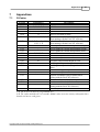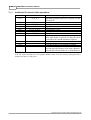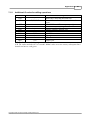
1
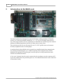
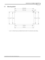
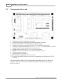
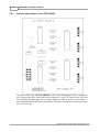
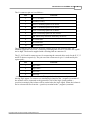
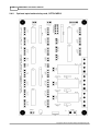
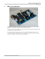
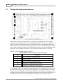
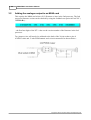
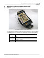
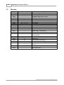
M640/M641 Installation Manual
Copyright © 2007 Conqueror Design and Engineering Ltd.
M640/M641 Installation Manual
Copyright © 2007 Conqueror Design and Engineering Ltd.
All rights reserved.
Any dispute about the use of this software and/or hardware or of these terms and conditions shall be resolved or
arbitrated under English Law.
Manuals and accompanying documentation may not be copied or printed for the purposes of training, advertising,
promotion or any other use without the permission of Conqueror Design and Engineering Limited.
Permission to copy and print manuals and documentation for personal use is granted to the owner/user of the
software supplied.
All trademarks are acknowledged to be the property of their respective owners.
This manual produced on 29/07/2007.
Warranty
This software and/or hardware and accompanying documentation are provided 'as-is' and are not warranted to be fit
for any specific purpose or usage.
The use of this software and/or hardware is undertaken at your own risk and Conqueror Design and Engineering
Limited will not be responsible for any loss of data, time or income resulting from the use of this software and/or
hardware.
Contents
I
Table of Contents
Part 1 Disclaimer of liability and limitation of warranty
1
Part 2 Introduction to the M640 card
2
1 Mounting
...................................................................................................................................
details
3
2 Components
...................................................................................................................................
of the card
4
3 RS232 ...................................................................................................................................
serial interface
5
4 Connector
...................................................................................................................................
for stepper motor drives
6
Optional opto-isolator
.........................................................................................................................................................
card, OPTOCARD
8
Optional opto-isolator/relay
.........................................................................................................................................................
card, OPTOCARD2
10
5 Connectors
...................................................................................................................................
for jog-buttons, limit-switches, optical-encoders and the safety-circuit
13
6 Relay...................................................................................................................................
driver connectors
14
7 Quadrature-encoders
...................................................................................................................................
/ closed-loop operation
16
Quadrature-encoders
......................................................................................................................................................... 17
Part 3 M641 card addendum
19
1 Changes
...................................................................................................................................
to the layout/connectors
20
2 Adding
...................................................................................................................................
the analogue output to an M640 card
22
Part 4 Encoder & photo-interrupter connections
23
1 GP1R11
...................................................................................................................................
quadrature-encoder
23
2 GP1A23
...................................................................................................................................
photo-interrupter
24
Part 5 Manual operation without a computer
25
Part 6 Direct control via the RS232
26
Part 7 Appendices
27
1 G-Codes
...................................................................................................................................
27
Additional G-codes
.........................................................................................................................................................
for lathe operations
28
Additional G-codes
.........................................................................................................................................................
for milling operations
29
2 M-codes
...................................................................................................................................
30
3 Command
...................................................................................................................................
set
31
4 Control
...................................................................................................................................
parameters
33
Copyright © 2007 Conqueror Design and Engineering Ltd.
I
II
M640/M641 Installation Manual
Index
38
Copyright © 2007 Conqueror Design and Engineering Ltd.
Disclaimer of liability and limitation of warranty
1
1
Disclaimer of liability and limitation of warranty
Where the M640/M641 is supplied as a component and not as part of a complete control
system it is assumed that the purchaser has sufficient electrical and electronic knowledge to
handle the component competently.
It is further assumed that the purchaser has sufficient knowledge of safe working practices
and the relevant Health & Safety regulations which apply to working with electrical and
electronic systems to work safely with the component.
Conqueror Design and Engineering Limited will not accept any liability for any damage to
systems or personnel that may result from the incorrect installation or usage of the
hardware supplied. Nor will Conqueror Design and Engineering Limited replace or repair
any supplied equipment that has been damaged as a result of such incorrect misuse or
installation.
Copyright © 2007 Conqueror Design and Engineering Ltd.
2
2
M640/M641 Installation Manual
Introduction to the M640 card
The M640 card has been designed to control CNC lathes, milling machines, PCB drills,
routers, etc. In fact any machine which has 1, 2, 3, 4, 5 or even 6 stepper motor driven
axes. The stepper motors can also, optionally, be controlled in a closed-loop mode with the
addition of standard quadrature encoders in either strip or rotary form.
The card also provides for on/off control for an AC or DC spindle motor and common
auxiliary equipment such as coolant pumps.
A machine fitted with an M640 can be operated in a simplified stand-alone manual mode
(for cleaning and maintenance, etc.) without requiring a host computer and, with the
addition of an optional LCD and keypad, can also operate in a fully stand-alone mode
similar to an industrial machine.
A low-cost 2-channel encoder can be connected to the quadrature encoder connector QH
to provide a hand-wheel for positioning the axes. The manual/stand-alone mode of the card
is 'hand-wheel' ready.
Copyright © 2007 Conqueror Design and Engineering Ltd.
Introduction to the M640 card
2.1
Mounting details
Copyright © 2007 Conqueror Design and Engineering Ltd.
3
4
2.2
M640/M641 Installation Manual
Components of the card
1.
2.
3.
4.
5.
6.
7.
8.
9.
10.
11.
Onboard processor for stand-alone operation.
Second processor for closed-loop operation (quadrature encoders).
Standard 9-pin RS232 for connection to a computer system.
Connector for stepper motor drives (Enable, Clock and Direction signals).
Connectors for discrete buttons for X+, X-, Y+, Y-, Z+, Z-, 9 limit switches, a control
button, 2 optical encoder channels and a safety circuit.
Spindle-motor-run relay drives - 2 12 volt 500 mA outputs.
Spindle-motor-reverse relay drive (uses general purpose relay #2).
Coolant-control relay driver.
2 general purpose relay drives.
External power supply input (12-35 volts DC).
Remotely upgradeable firmware (firmware is upgradeable from within the EaziCNC
software).
The card is supplied with EaziCNC editing and programming software for Microsoft
Windows. Please refer to the separate EaziCNC manual for details on operating the
EaziCNC software.
Copyright © 2007 Conqueror Design and Engineering Ltd.
Introduction to the M640 card
2.3
5
RS232 serial interface
Pin
Signal
2
Receive Data (RCD)
3
Transmit Data (TXD)
5
Ground
The serial port is configured as a standard PC AT 9-pin port. A standard PC-AT to PC-AT
serial cable (a cross-over cable) can be used.
The default protocols are 115200 baud, 8 data bits, no parity and 1 stop bit (older cards
may operate at either 19200 or 38400 baud until the firmware is updated).
The board will use XON/XOFF flow controls by default.
If you are making your own cable you should wire it as follows (if you use shielded cable
connect the shield to the plug casing at the PC end only!)...
Copyright © 2007 Conqueror Design and Engineering Ltd.
PC
M641
2
3
3
2
5
5
6
2.4
M640/M641 Installation Manual
Connector for stepper motor drives
Pin
Function
1
VCC (+5-volts).
2
Ground (0-volts).
3
STPX. Clock/Step-pulse for X motor.
4
STPY. Clock/Step-pulse for Y motor.
5
STPZ. Clock/Step-pulse for Z motor.
6
STPE. Clock/Step-pulse for E/U motor.
7
DIR. Motor step direction. Shared by all drives. [or
direction for X only if separate direction outputs are
selected]
8
ENABLE. Used to idle the stepper motor drives when not
in use. [or direction for Y only if separate direction outputs
are selected]
9
STPV. Clock/Step-pulse for V motor. [or direction for Z
only if separate direction outputs are selected]
10
STPW. Clock/Step-pulse for W motor. [or direction for
E/U only if separate direction outputs are selected]
Connector J2 at the bottom left of the M640 card is used to attach the separate stepper
motor drive cards.
If the stepper motor drive cards STEP1, STEP2, STEPHP1 or SERVO1 are used then the
connections to the cards can be made via a straight ribbon cable "bus" and the cards can be
configured to identify as X, Y, Z, E/U, V or W. If other drive cards are used then it will
Copyright © 2007 Conqueror Design and Engineering Ltd.
Introduction to the M640 card
7
probably be necessary to use a terminal block or Y-cables to connect the shared signals to
the different cards.
N.B. It is possible to select separate direction outputs for the X, Y, Z and E motors for
use with motor control cards that require the direction signal to be held constant
between step pulses. If this option is selected (see the control parameters section) then it
is not possible to control the V and W motors or to make use of the auto-power-down
function of the M640 card.
The timing of the motor control signals from the M640 card is...
Copyright © 2007 Conqueror Design and Engineering Ltd.
8
2.4.1
M640/M641 Installation Manual
Optional opto-isolator card, OPTOCARD
The opto-isolator card, OPTOCARD(R1), allows the external stepper drive card signals
to be connected to drive cards which do not operate at 5-volt TTL signal levels. The card
also splits the direction signal into 4 separate outputs to make it easier to connect drive
cards which need individual directions signals. The card is suitable for interfacing to logic
levels of 5-50 volts.
Copyright © 2007 Conqueror Design and Engineering Ltd.
Introduction to the M640 card
9
The J1 connector pin out is as follows...
Pin
Function
1
VCC (+5-volts).
2
Ground (0-volts).
3
STPX. Clock/Step-pulse for X motor.
4
STPY. Clock/Step-pulse for Y motor.
5
STPZ. Clock/Step-pulse for Z motor.
6
STPE. Clock/Step-pulse for E/U motor.
7
DIR. Motor step direction. Shared by all drives.
8
No connection.
9
No connection.
10
No connection.
The J2 connector can be used to invert the signals going to the external cards. The
standard signals are active-low. Connecting a shorting link across J2 will make the signals
active-high. The board is supplied with a shorting link on connector J2.
The J3, J4, J5 and J6 connectors are for connecting the external drive cards for the X, Y, Z
and E/U motors respectively. The pin out of the connectors is (pin 1 is indicated by the
square pad)...
Pin
Function
1
Step clock -
2
Step clock +
3
Direction +
4
Direction -
...each opto-isolator can shunt 25 mA. The opto-isolated outputs are only suitable for
driving logic inputs. To connect to a standard logic interface the - (negative) terminal of
the isolator will be connected to the ground (0v) rail of the logic system and the +
(positive) terminal of the isolator will be connected to the logic signal. When the isolator is
active current will flow from the + (positive) terminal to the - (negative) terminal.
Copyright © 2007 Conqueror Design and Engineering Ltd.
10
2.4.2
M640/M641 Installation Manual
Optional opto-isolator/relay card, OPTOCARD2
Copyright © 2007 Conqueror Design and Engineering Ltd.
Introduction to the M640 card
11
The opto-isolator card, OPTOCARD2, allows the external stepper drive card signals to be
connected to drive cards which do not operate at 5-volt TTL signal levels. The card also
splits the direction signal into 4 separate outputs to make it easier to connect drive cards
which need individual directions signals. The card is suitable for interfacing to logic levels
of 5-50 volts.
The OPTOCARD2 also includes power-relays for interfacing high-current loads to the
M640/M641 and optically-isolated jog-panel and limit-switch connectors which can
operate at 12-volts.
The STEPBUS connector pin out is as follows...
Pin
Function
1
VCC (+5-volts).
2
Ground (0-volts).
3
STPX. Clock/Step-pulse for X motor.
4
STPY. Clock/Step-pulse for Y motor.
5
STPZ. Clock/Step-pulse for Z motor.
6
STPE. Clock/Step-pulse for E/U motor.
7
DIR. Motor step direction. Shared by all drives.
8
No connection.
9
No connection.
10
No connection.
The XSTP, YSTP, ZSTP and USTP connectors are for connecting the external drive cards
for the X, Y, Z and E/U motors respectively. The pin out of the connectors is (pin 1 is
indicated by the square pad)...
Pin
Function
1
Step clock -
2
Step clock +
3
Direction +
4
Direction -
...each opto-isolator can shunt 25 mA. The opto-isolated outputs are only suitable for
driving logic inputs or other opto-isolators. To connect to a standard logic interface the (negative) terminal of the isolator will be connected to the ground (0v) rail of the logic
system and the + (positive) terminal of the isolator will be connected to the logic signal.
When the isolator is active current will flow from the + (positive) terminal to the (negative) terminal. The XD/S, YD/S, ZD/S and UD/S jumpers select whether the
direction outputs for each connector are from the shared direction signal or separate
direction signals.
Copyright © 2007 Conqueror Design and Engineering Ltd.
12
M640/M641 Installation Manual
The X+X-, Y+Y-, Z+Z-, etc. connect to the input plugs on the X641 card. The BX+X-,
BY+Y-, etc. are the 12-volt buffered connections for the buttons and switches on the
machine.
Copyright © 2007 Conqueror Design and Engineering Ltd.
Introduction to the M640 card
2.5
13
Connectors for jog-buttons, limit-switches, optical-encoders and
the safety-circuit
The connectors for the jog-buttons, limit-switches, optical encoders and the safety circuit
are located along the top edge of the board...
In each case the square pad located inside each connector indicates pin1 (it is at the right of
the connector in each case). FB1 and FB2 are the threading sensors - FB1 is the single-slot
(1 count/rev) and FB2 is the multi-slot.
X+, X-, Y+, Y-, Z+ and Z- axis jog-button, BN1 connectors, LIME, LIMV, LIMW
Pin
Function
1
Button signal. Short to pin 2 to activate button (i.e.,
connect the switch across the 2 pins)
2
Ground
FB1 and FB2 optical-encoder connectors
Pin
Function
1
VCC (+5-volts).
2
Encoder signal.
3
Ground (0-volts).
STP - safety-circuit connector
Pin
Function
1
Safety circuit +.
2
Safety circuit LIM1, LIM2, LIM3 and LIM4 limit-switch connectors
Pin
Function
1
Positive travel limit signal. Short to pin 2 to activate limit
(i.e., connect the switch across the 2 pins)
2
Ground (0-volts).
3
Negative travel limit signal. Short to pin 4 to activate limit
(i.e., connect the switch across the 2 pins)
4
Ground (0-volts).
Copyright © 2007 Conqueror Design and Engineering Ltd.
14
2.6
M640/M641 Installation Manual
Relay driver connectors
The relay connectors are located along the right edge of the M640.
In each case pin 1 is the square pin in the connector (In practice the polarity of the
connections does not matter unless solid-state relays are used).
Pin
Function
1
+ relay drive voltage.
2
- relay drive voltage.
The onboard relay drives can drive relays requiring up to 500 mA but the combined current
for all relays & fans should not exceed 1,250 mA.
Relay
Function
REM1
To control the spindle motor run/stop.
REM2
To control the spindle motor run/stop.
REC
To control the coolant pump if fitted.
RE1
Auxiliary relay #1
Copyright © 2007 Conqueror Design and Engineering Ltd.
Introduction to the M640 card
RE2
Auxiliary relay #2. Also used if the spindle motor is
reversed.
FAN1
Always on... can drive cooling fans, work-lights, etc.
FAN2
Always on... can drive cooling fans, work-lights, etc.
15
Any relays connected to the drivers should be fitted with suitable snubbers to protect the
loads that they are driving.
Copyright © 2007 Conqueror Design and Engineering Ltd.
16
2.7
M640/M641 Installation Manual
Quadrature-encoders / closed-loop operation
The card has connectors for 6 quadrature-encoders... for the axes X, Y, Z, E/U, V and W.
Pin 1 in each case is the square pad.
In most configurations the 6th encoder (QH) is used for an electronic hand-wheel for axis
positioning.
QH, QX, QY,QZ,QE/U and QV Quadrature Encoder connectors
Pin
Function
1
VCC (+5-volts).
2
Encoder channel A
3
Encoder channel B
4
Ground (0-volts).
Copyright © 2007 Conqueror Design and Engineering Ltd.
Introduction to the M640 card
2.7.1
17
Quadrature-encoders
Quadrature-encoders output 2 pulse trains, A and B, which are out of phase. The
'quadrature' in the name is derived from the fact that there are 4 states for the 2 signals to
be in... A-off-with-B-off, A-on-with-B-off, A-on-with-B-on and A-off-with-B-on. The
sequence of these states determines the direction of rotation of the encoder (and the motor
or shaft that it is attached too)...
For feedback from the motors optical encoders are usually used...
Copyright © 2007 Conqueror Design and Engineering Ltd.
18
M640/M641 Installation Manual
...because they place no load on the drive system and can cope with the high speeds that
motors and shafts may turn at. The encoder pictured is a rotary encoder with a slotted
disk... the disk determines the resolution of the encoder... in this case 400 counts/rev.
Optical encoders also come in strip or linear forms and there are other types of non-contact
encoders that can be used (such as capacitance strips or magnetic proximity switches).
For the hand wheel a mechanical (cheaper!) encoder/switch can be used...
...these operate using a wafer switch but provide the same quadrature outputs as an optical
encoder... they are just not suitable for high-speed or long-life applications. Another
advantage of these mechanical encoders is that they often have detents (a cogging feel as
they are rotated). The encoder shown is a Bourne ECW1J-B24-AC0024 it provides 96
counts per revolution and is the encoder we use for the hand wheel on the CNC1 and
CNC2 boxed controllers.
Copyright © 2007 Conqueror Design and Engineering Ltd.
M641 card addendum
3
19
M641 card addendum
The M641 is an update to the M640 card. An additional 2 relay drivers have been added
together with an analogue output for controlling a spindle motor.
The M641 also has an I2C (Phillips serial bus) connector so that an almost limitless amount
of expansion can be added if required.
It is possible to add the analogue speed control to an M640 card with a small external
circuit if the firmware of the 2nd processor is updated to version 0103 or later... the other
features of the M641 cannot be retro-fitted to the M640.
Copyright © 2007 Conqueror Design and Engineering Ltd.
20
3.1
M640/M641 Installation Manual
Changes to the layout/connectors
Most of the connectors are in the same locations as for the M640 card. The feedback
connectors QZ, QE/U and QV have moved slightly and there are four new connectors... an
SPI/I2C connector on the left edge of the card and two new relay connectors (RE3 and
RE4) and a new 5 pin connector on the right of the card. There is additional space between
many of the connectors to improve the way that the sockets lie on the board and the labels
have been moved slightly so that they are still visible when the connectors are fitted.
The new 5 pin connector is wired as follows...
MSPEEDMON connector (pin 1 is the square pin)
Pin
Function
1
Positive supply for analogue output
2
Analogue output
3
Negative supply for analogue output
4
Terminal 1 of 'motor on' relay (if fitted).
5
Terminal 2 of 'motor on' relay (if fitted).
If for instance a DC or AC spindle card has connections for a potentiometer to control the
speed then the analogue speed control is wired with pin 1 to the high/positive side of the
pot, pin 3 to the low/negative side of the pot and pin 2 to the wiper (or variable pin). The
analogue speed control will not put any higher loading on the motor card supply than a 10
KOhm potentiometer and it is optically isolated from the rest of the M641 control.
Copyright © 2007 Conqueror Design and Engineering Ltd.
M641 card addendum
21
If the optional spindle on/off relay is fitted then pins 4 and 5 are the contacts of the relay.
Jumper JP1 can be used to select whether the contacts are normally open (NO) or normally
closed (NC). If a spindle speed card is used which has connections for a
low-volt/low-current enable switch then it can be wired to these connections. The optional
relay should not be used to switch voltages higher than 120VAC/30VDC or loads larger
than 1 Amp (the relay is rated @ 120VA). If higher voltages or currents are required then
an off-board relay should be connected to the REM1 relay driver.
Copyright © 2007 Conqueror Design and Engineering Ltd.
22
3.2
M640/M641 Installation Manual
Adding the analogue output to an M640 card
This requires the M640 card to have 0103 firmware or later in the 2nd processor. The 2nd
processor firmware version can be checked by using the feedback test option in EaziCNC (
<CTRL+B>)...
...the first four digits of the 'ST:' value are the version number of the firmware in the 2nd
processor.
Two jumper wires will need to be soldered to the back of the 28 pin socket to pins 8
(GND/O-volts) and 13 (the PWM output) and a circuit constructed as shown below...
Copyright © 2007 Conqueror Design and Engineering Ltd.
Encoder & photo-interrupter connections
4
Encoder & photo-interrupter connections
4.1
GP1R11 quadrature-encoder
23
Sharp GP1R11 Quadrature-encoder and connections
The Sharp GP1R11 quadrature-encoder connections are shown above. There is a small
plus mark next to the +5V connection and a small negative next to the GND connection.
Pin
Function
1
+5V
2
A channel of encoder
3
B channel of encoder
4
GND
Copyright © 2007 Conqueror Design and Engineering Ltd.
24
4.2
M640/M641 Installation Manual
GP1A23 photo-interrupter
Sharp GP1A23 photo-interrupter
The Sharp GP1A23LC photo-interrupter connections are shown above. Pin 1 is closest to
the lettering/marking on the part.
Pin
Function
1
+5V
2
GND
3
SIGNAL - photo-interrupter output
Copyright © 2007 Conqueror Design and Engineering Ltd.
Manual operation without a computer
5
25
Manual operation without a computer
If no computer is attached the machine can be used in a rudimentary manner using the
following jog-button and BN1 (button 1) combinations. the jog-switches operate as normal
in manual mode when BN1 is not pressed.
Keys pressed
Action
BN1 & X+
Enter manual mode.
BN1 & X-
Exit manual mode.
BN1 & Y+
Turn spindle/spindle-relay on
BN1 & Y-
Turn spindle/spindle-relay off
BN1 & Z+
Toggle rapid and feed modes.
BN1 & Z-
Toggle coolant on/off.
If no button has been pressed for several minutes the machine will be switched out of
manual mode.
Copyright © 2007 Conqueror Design and Engineering Ltd.
26
6
M640/M641 Installation Manual
Direct control via the RS232
It is possible to control the M640/M641 directly from the serial port without using the
EaziCNC or EaziCNCLite programmes.
The M640/M641 accepts a subset of the full set of G & M codes (for instance no circular
interpolation, no splines and no canned cycles) that EaziCNC supports, coordinates need
to be in millimetres and only absolute positioning is supported. Also you need to deal with
the handshaking from the machine to make sure that commands do not get overwritten
before they can be executed.
To test this from, for instance, HyperTerminal...
1. Open a connection to the M641 at 115200 baud, 8 data bits, no-parity and 1
stop bit with Xon/Xoff handshaking.
2. Type <CTRL+E>... this will turn on the echo so that you can see the keys typed
and the responses from the M641. You should also turn on the option to add
line-feeds to carriage returns (N.B. <CTRL+N> turns the echo off... the
controller will not send anything back via the RS232 that is not requested... this
keeps the interface 'clean' for very rapid communication from a programme like
EaziCNC).
3. If you hit <Enter> you should see the '>' prompt.
4. You can now enter commands such as 'ST' to show the status, 'M3' to turn on
the spindle and 'G0 X10' to move (before you do any moves you may need to
send an 'EC' to clear the error-state... by default the controller will power-up
with error #3 - power-on).
5. If you want to see a rolling display of the coordinate changes as a movement
command is executed then enter 'D1' (and 'D0' to turn the feature off).
6. The controller will send status information back to a control programme if
certain characters are sent... for instance sending a '@' will return X, Y, Z and E
positions, the key panel code and a status byte as a packed hexadecimal string.
There are other codes which will return information from the box either as text,
packed hexadecimal or binary-blobs.
In the raw 'terminal' mode any axis commands (such as 'X10' or 'Y1.26') will be interpreted
as millimetres using the parameters to convert them into an accurate number of steps... the
coordinates shown by the status commands are also shown in millimetres with 2 decimal
places (0.01) but no decimal points are shown. Any of the commands that return data in a
packed format return the raw step values.
There are a couple of ways to go depending on how sophisticated your control of the
machine needs to be... you can either write your own interface to the controller which
sends commands out of the serial port direct *or* there is a DLL available which contains
a 'virtual'-machine that supports all of the commands that EaziCNC does and that can be
easily integrated into any programme. The DLL takes care of all the serial communication
to the machine and exposes a command function and a query function to the calling
programme.
Copyright © 2007 Conqueror Design and Engineering Ltd.
Appendices
7
Appendices
7.1
G-Codes
G-Code
G00*
G01*
G02*
G03*
G04
G06*
Parameters
X, Y, Z, E
X, Y, Z, E, F
X, Y, Z, E, I, J, K, F, R
X, Y, Z, E, I, J, K, F, R
S
X, Y, Z, E, A, B, C, D, P
27
Description
Rapid Move
Feed Move
Arc Clockwise Move
Arc Counter-Clockwise Move
Dwell. S=Seconds to delay.
Spline functions (Cubic curve) (only available
when running with the EaziCNC software)
G07*
X, Y, Z, E, A, B, C, D, Spline functions (Bezier curve) (only available
I, J,K, L, P
when running with the EaziCNC software)
G17
Use XY plane for circular interpolation (Top)
G18
Use XZ plane for circular interpolation (Front)
G19
Use YZ plane for circular interpolation (Side)
G28
X, Y, Z, E
Home Axis
G40
Tool-nose compensation off (default mode)
G41
R
Tool-nose compensation Left-of-Line
G42
R
Tool-nose compensation Right-of-Line
G43
Tool-length compensation (positive)
G44
Tool-length compensation (negative - default
mode)
G45
Cancel Tool-length compensation.
G54
X, Y, Z, E
Set home/reset position.
G70
Imperial coordinates (only available when
running with the EaziCNC software)
G71
Metric coordinates (default mode)
G90
Absolute coordinates (default mode)
G91
Incremental coordinates (only available when
running with the EaziCNC software)
G92
X, Y, Z, E
Set datum point.
N.B. The E axis can also be programmed as U.
N.B. The codes marked with * are modal. Modal codes are active on any subsequent lines
that do not have a code given.
Copyright © 2007 Conqueror Design and Engineering Ltd.
28
7.1.1
M640/M641 Installation Manual
Additional G-codes for lathe operations
G-Code
G33
Parameters
X, Z, P, I
Description
Threading(/synchronized) cut. P is pitch, I is end
pull-out in X.
G80
Cancel Canned Cycle
G81*
X, Z, P
Turning cycle
G82*
X, Z, P
Taper cycle
G83*
X, Z, I, K, R, P
Arc Clockwise Cycle
G84*
X, Z, I, K, R, P
Arc Counter-Clockwise Cycle
G85*
X, Z, P
Facing Cycle
G86*
X, Z, P, I, K, R
Threading(/synchronized) cut cycle. X is pass
offset (pass depth). P is pitch, I is end pull-out, K
is pass offset in Z and R is number of passes.
G94
Feed rates in mm./in. per minute
G95
Feed rates in mm./in. per spindle revolution
G96
Constant surface speed.
Feed rate specified in mm. at 20.0 mm. diameter.
Feed rate specified in inches at 1.0 inch diameter.
N.B. The E axis can also be programmed as U.
N.B. The codes marked with * are modal. Modal codes are active on any subsequent lines
that do not have a code given.
Copyright © 2007 Conqueror Design and Engineering Ltd.
Appendices
7.1.2
29
Additional G-codes for milling operations
G-Code
G50
G51
Parameters
X, Y, Z, E
Description
Mirror Off. Cancel any mirrored axis.
Mirror. Mirror selected axis (around coordinate
given).
G55
Offset Off. Cancel/Clear temporary origin
G56
X, Y, Z, E
Offset. Set temporary origin.
G80
Cancel/Complete Canned Cycle.
G81*
Z
Drill, Spot-Drill
G82*
Z, K
Peck Drill
G83*
Z, P
Tapping
G84*
Z
Bore
G85*
Z, P
Pocket cycle.
N.B. The E axis can also be programmed as U.
N.B. The codes marked with * are modal. Modal codes are active on any subsequent lines
that do not have a code given.
Copyright © 2007 Conqueror Design and Engineering Ltd.
30
7.2
M640/M641 Installation Manual
M-codes
M-Code
M00
M01
M02
M03
M04
M05
M06
M08
M09
M13
M14
M15
M30
M47
Parameters
S
S
R, T, X, Y, Z
S
S
R
M90
M91
M92
M93
M94
P
P
P
P
-
M98
M99
-
Description
Programme Stop
Optional Stop
Programme End (same as M30)
Spindle Start Clockwise
Spindle Start Counter-clockwise
Spindle Stop
Tool Change
Coolant On
Coolant Off
Spindle Start Clockwise + Coolant On
Spindle Start Counter-clockwise + Coolant On
Spindle Stop + Coolant Off
Programme End (same as M02)
Return to Programme Start. R is the repeat
count (if given)
Relay P On
Relay P Off
Wait for input P to be Low
Wait for input P to be High
Index tool-post. Indexes the tool-post (if fitted)
forward.
Motor Drives On
Motor Drives Off
Copyright © 2007 Conqueror Design and Engineering Ltd.
Appendices
7.3
31
Command set
Command
Ctrl-B (#2)
Ctrl-E (#5)
Parameters
-
Ctrl-N (#14)
-
<ESC>
-
@
-
D
n<CR>
EC
-
ES
-
I
n<CR>
MA
<CR>
Copyright © 2007 Conqueror Design and Engineering Ltd.
Description
Query. Used by the EaziCNC software.
Echo On. Echoes characters back to the terminal
and enables user friendly responses (data sent to
the terminal will have a tag, i.e, "P0:0" instead of
just "0").
Echo Off. Stops characters from being echoed
back to the terminal and disables user friendly
responses.
Escape. Stops any current moves or commands.
Clears the command buffers. This command does
not need to be completed with a carriage return
(CR).
At. Returns the current position and status data
in compressed hex format. This command does
not need to be completed with a carriage return
(CR).
Message-mode. Controls whether messages are
sent to the console.
n=0 - do not show messages
n=1 - show messages (including updates when
moving)
n=2 - debugging mode
Error Clear. Clears any error state on the
machine.
N.B. this clears user-stops, power-up errors, etc.
it will not and cannot clear errors such as
'safety activated'.
Error Status. Displays the error code of the
machine.
Error codes...
0 - No error
1 - Stopped by user
2 - Stopped - safety activated
3 - Power interrupted
4 - X-limit triggered
5 - Y-limit triggered
6 - Z-limit triggered
7 - E-limit triggered
Info. <n> is the item of information
0 - board ID
1 - firmware version
2 - firmware date
3 - processor type
<blank> - firmware banner
Manual Mode. To exit manual mode the <ESC>
32
M640/M641 Installation Manual
P
n[ Rv]<CR>
SX
SY
SZ
SE
SH
f<CR>
f<CR>
f<CR>
f<CR>
<CR>
ST
T
<CR>
X, Y, Z
command must be sent.
Parameter. Query (or set) a parameter. See
control parameters for a description. P99 will
display parameters 0 to 19, P199 will display
parameters 20 to 39 and P299 will display
parameters 40 to 59.
Set X coordinate to <f>
Set Y coordinate to <f>
Set Z coordinate to <f>
Set E coordinate to <f>
Show Home. Displays the currently set
home/starting position (set by a G54 command).
Status. Show current status.
Set/display tool offset. If no X, Y or Z is given
then the existing offset will be displayed. T99
will list all tool offsets.
Any valid ISO line will also be interpreted and executed on the machine tool. For a list of
valid ISO (G&M-codes) see G-Codes and M-Codes.
Copyright © 2007 Conqueror Design and Engineering Ltd.
Appendices
7.4
33
Control parameters
Parameter
0
Type
Binary
1
Binary
2
Integer
3
Integer
4
Integer
5
Integer
6
Integer
7
Integer
8
Integer
9
Integer
10
Integer
11
Integer
12
Integer
13
Integer
14
Integer
15
Integer
16
Integer
17
Integer
18
Integer
Copyright © 2007 Conqueror Design and Engineering Ltd.
Description
Configuration 1 - see detailed
explanation below.
Configuration 2 - see detailed
explanation below.
Minimum Spindle Speed. Default=200
RPM
Maximum Spindle Speed. Default=2000
RPM
Maximum Cutting Feed Rate.
Default=400 mm./min.
Rapid Feed Rate. Default=800
mm./min.
Pulses/Revolution on
Threading/Synchronizing Encoder.
Default=360
[Setting this to 0 will cause the slots to
be counted]
Default Circular Interpolation Mode.
0=XY, 1=XZ, 2=YZ.
X-scale (X-step size in millimetres =
(P9/P8)/P19)
X-divisor (X-step size in millimetres =
(P9/P8)/P19)
Y-scale (Y-step size in millimetres =
(P11/P10)/P19)
Y-divisor (Y-step size in millimetres =
(P11/P10)/P19)
Z-scale (Z-step size in millimetres =
(P13/P12)/P19)
Z-divisor (Z-step size in millimetres =
(P13/P12)/P19)
E/U-scale (E-step size in millimetres =
(P15/P14)/P19)
Also used for V & W
E/U-divisor (E-step size in millimetres =
(P15/P14)/P19)
Also used for V & W
Scalar for Feed rates.
Steps/sec=625,000*P17/(Feed*P16).
Divisor for Feed rates.
Steps/sec=625,000*P17/(Feed*P16).
Decimal digits in coordinates. Default=2
digits
34
M640/M641 Installation Manual
19
20
Integer
Binary
21
Integer
22
Integer
23
24
25
26
27
28
29
30
31
32
33
34
35
36
37
38
39
Integer
Integer
Integer
Integer
Integer
Integer
Integer
Integer
Integer
Integer
Integer
Integer
Integer
Integer
Integer
Integer
Integer
40
Integer
41
Integer
42
Integer
43
Integer
44
Integer
45
Integer
46
Integer
47
Integer
Divisor for coordinates. Default=100
Control capabilities (see detailed
description below). Do not alter!
Delays for carousel tool post.
Forward delay = (low byte + 1)*0.25
secs
Reverse delay = (high byte + 1)*0.25
secs
[For stepper driven carousels 32768
(high bit) + steps/100. Reverse is half of
forward steps]
Time-out for manual mode and
automatic motor turn-off
Ramp stages (Maximum 16)
Ramp 0
Ramp 1
Ramp 2
Ramp 3
Ramp 4
Ramp 5
Ramp 6
Ramp 7
Ramp 8
Ramp 9
Ramp 10
Ramp 11
Ramp 12
Ramp 13
Ramp 14
Ramp 15
Back-lash compensation for X axis
(steps)
Back-lash compensation for Y axis
(steps)
Back-lash compensation for Z axis
(steps)
Back-lash compensation for E/U axis
(steps)
Back-lash compensation for V axis
(steps)
Back-lash compensation for W axis
(steps)
Low byte - deadband for X, high byte deadband for Y
Low byte - deadband for Z, high byte -
Copyright © 2007 Conqueror Design and Engineering Ltd.
Appendices
48
Integer
49
50
51
52
53
54
55
56
57
58
59
Integer
Integer
Integer
Integer
Integer
Integer
Integer
Integer
Integer
Integer
Integer
Copyright © 2007 Conqueror Design and Engineering Ltd.
35
deadband for E/U
Low byte - deadband for V, high byte deadband for W
Max. encoder failure count allowed
X-encoder scale
X-encoder divisor
Y-encoder scale
Y-encoder divisor
Z-encoder scale
Z-encoder divisor
U/V/W-encoder scale
U/V/W-encoder divisor
Reserved
Reserved
36
M640/M641 Installation Manual
Configuration 1 (parameter 0)
bit 1
X axis direction
bit 2
Y axis direction
bit 3
Z axis direction
bit 4
E axis direction
bit 5
X axis home direction
bit 6
Y axis home direction
bit 7
Z axis home direction
bit 8
E axis home direction
bit 9
Turn off motor drives when inactive
bit 10
Override Safety switch (spindle and coolant will not run)
bit 11
Override Safety switch (spindle and coolant will run). MPC4 & MPC5 only.
bit 12
LED4 shows busy state (MPC4/MPC5 only)
bit 13
RELAY4 is reserved for motor reverse (MPC4/MPC5 only)
bit 14
tool carousel on motor E. [delay is (param21+1)*0.25 secs]
bit 15
Separate direction outputs for X, Y, Z & E (M640 only)
bit 16
Enable hand-wheel to be used for feed-rate override
Configuration 2 (parameter 1)
bit 1
X feedback active
bit 2
Y feedback active
bit 3
Z feedback active
bit 4
E feedback active
bit 5
X limit active
bit 6
Y limit active
bit 7
Z limit active
bit 8
U limit active
bit 9
X limit positive is NC (normally closed)
bit 10
X limit negative is NC (normally closed)
bit 11
Y limit positive is NC (normally closed)
bit 12
Y limit negative is NC (normally closed)
bit 13
Z limit positive is NC (normally closed)
bit 14
Z limit negative is NC (normally closed)
bit 15
U limit positive is NC (normally closed)
bit 16
U limit negative is NC (normally closed)
Control Capabilities (parameter 20)
bit 1
0 - Control does not support G2/G3 directly
1 - Control supports G2/G3 directly
bit 2
reserved
bit 3
reserved
bit 4
reserved
bit 5
reserved
Copyright © 2007 Conqueror Design and Engineering Ltd.
Appendices
bit 6
bit 7
bit 8
bit 9
bit 10
bit 11
bit 12
bit 13
bit 14
bit 15
bit 16
reserved
reserved
reserved
reserved
reserved
reserved
reserved
reserved
reserved
reserved
reserved
Copyright © 2007 Conqueror Design and Engineering Ltd.
37
38
M640/M641 Installation Manual
Index
-QQuadrature-encoders
-B-
16, 17
-S-
Board layout
4
Stand-alone operation
-C-
25
-T-
Closed-loop 16
Command Set 31
Connector positions 4
Connectors
Jog-buttons 13
Limit switches 13
Optical-encoders 13
Quadrature-encoders 16
Relays 14
RS232 5
Safety-circuit 13
Spindle speed control 20
Stepper motor drives 6
Threading sensors, FB1 & FB2
13
-DDisclaimer of liability
1
-GG-codes
GP1A23
GP1R11
27
24
23
-IIntroduction to the card
2
-LLathe 27, 28
Limitation of warranty
1
-MM640
Adding speed control
M641 19, 20
M-codes 30
Mill 27, 29
Mounting details
22
3
-OOPTOCARD 8
OPTOCARD2 10
Opto-isolator card 8
Opto-isolator/relay card
10
-PParameters
33
Copyright © 2007 Conqueror Design and Engineering Ltd.