1
Cat. No. W378-E1-02
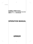
SYSMAC CS Series
CS1W-HIO01-V1/HCP22-V1/HCA22-V1/HCA12-V1
Customizable Counter Units
OPERATION MANUAL
CS1W-HIO01-V1/HCP22-V1/HCA22-V1/
HCA12-V1
Customizable Counter Units
Operation Manual
Revised December 2003
iv
Notice:
OMRON products are manufactured for use according to proper procedures by a qualified operator
and only for the purposes described in this manual.
The following conventions are used to indicate and classify precautions in this manual. Always heed
the information provided with them. Failure to heed precautions can result in injury to people or damage to property.
!DANGER
Indicates an imminently hazardous situation which, if not avoided, will result in death or
serious injury.
!WARNING
Indicates a potentially hazardous situation which, if not avoided, could result in death or
serious injury.
!Caution
Indicates a potentially hazardous situation which, if not avoided, may result in minor or
moderate injury, or property damage.
OMRON Product References
All OMRON products are capitalized in this manual. The word “Unit” is also capitalized when it refers to
an OMRON product, regardless of whether or not it appears in the proper name of the product.
The abbreviation “Ch,” which appears in some displays and on some OMRON products, often means
“word” and is abbreviated “Wd” in documentation in this sense.
The abbreviation “PLC” means Programmable Controller. “PC” is used, however, in some Programming Device displays to mean Programmable Controller.
Visual Aids
The following headings appear in the left column of the manual to help you locate different types of
information.
Note
Indicates information of particular interest for efficient and convenient operation of the product.
Reference
Indicates supplementary information on related topics that may be of interest to the user.
1,2,3...
1. Indicates lists of one sort or another, such as procedures, checklists, etc.
Ó OMRON, 2001
All rights reserved. No part of this publication may be reproduced, stored in a retrieval system, or transmitted, in any form, or
by any means, mechanical, electronic, photocopying, recording, or otherwise, without the prior written permission of
OMRON.
No patent liability is assumed with respect to the use of the information contained herein. Moreover, because OMRON is constantly striving to improve its high-quality products, the information contained in this manual is subject to change without
notice. Every precaution has been taken in the preparation of this manual. Nevertheless, OMRON assumes no responsibility
for errors or omissions. Neither is any liability assumed for damages resulting from the use of the information contained in
this publication.
v
vi
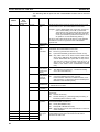
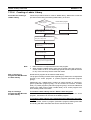
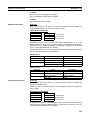
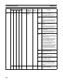
TABLE OF CONTENTS
PRECAUTIONS . . . . . . . . . . . . . . . . . . . . . . . . . . . . . . . . . . .
1
2
3
4
5
6
7
xi
Intended Audience . . . . . . . . . . . . . . . . . . . . . . . . . . . . . . . . . . . . . . . . . . . . . . . . . . . . . . . .
General Precautions . . . . . . . . . . . . . . . . . . . . . . . . . . . . . . . . . . . . . . . . . . . . . . . . . . . . . . .
Safety Precautions. . . . . . . . . . . . . . . . . . . . . . . . . . . . . . . . . . . . . . . . . . . . . . . . . . . . . . . . .
Operating Environment Precautions . . . . . . . . . . . . . . . . . . . . . . . . . . . . . . . . . . . . . . . . . . .
Application Precautions . . . . . . . . . . . . . . . . . . . . . . . . . . . . . . . . . . . . . . . . . . . . . . . . . . . .
Data Backup . . . . . . . . . . . . . . . . . . . . . . . . . . . . . . . . . . . . . . . . . . . . . . . . . . . . . . . . . . . . .
Conformance to EC Directives . . . . . . . . . . . . . . . . . . . . . . . . . . . . . . . . . . . . . . . . . . . . . . .
xii
xii
xii
xiii
xiv
xvi
xviii
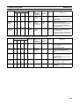
SECTION 1
Features and System Configuration . . . . . . . . . . . . . . . . . . .
1
1-1
1-2
Outline. . . . . . . . . . . . . . . . . . . . . . . . . . . . . . . . . . . . . . . . . . . . . . . . . . . . . . . . . . . . . . . . . .
Models and System Configurations . . . . . . . . . . . . . . . . . . . . . . . . . . . . . . . . . . . . . . . . . . .
2
14
SECTION 2
Specifications. . . . . . . . . . . . . . . . . . . . . . . . . . . . . . . . . . . . . .
19
2-1
2-2
Performance Specifications. . . . . . . . . . . . . . . . . . . . . . . . . . . . . . . . . . . . . . . . . . . . . . . . . .
Contact I/O Specifications (All Units) . . . . . . . . . . . . . . . . . . . . . . . . . . . . . . . . . . . . . . . . .
20
33
SECTION 3
Nomenclature, Installation, and Wiring. . . . . . . . . . . . . . . .
35
3-1
3-2
3-3
3-4
3-5
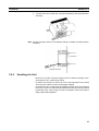
Names and Functions of Parts. . . . . . . . . . . . . . . . . . . . . . . . . . . . . . . . . . . . . . . . . . . . . . . .
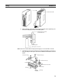
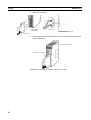
Installation. . . . . . . . . . . . . . . . . . . . . . . . . . . . . . . . . . . . . . . . . . . . . . . . . . . . . . . . . . . . . . .
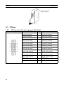
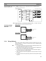
Wiring . . . . . . . . . . . . . . . . . . . . . . . . . . . . . . . . . . . . . . . . . . . . . . . . . . . . . . . . . . . . . . . . . .
Programming Devices. . . . . . . . . . . . . . . . . . . . . . . . . . . . . . . . . . . . . . . . . . . . . . . . . . . . . .
Fail-safe Circuits . . . . . . . . . . . . . . . . . . . . . . . . . . . . . . . . . . . . . . . . . . . . . . . . . . . . . . . . . .
36
39
42
53
56
SECTION 4
Exchanging Data with the CPU Unit . . . . . . . . . . . . . . . . . .
59
4-1
4-2
4-3
4-4
4-5
Overview . . . . . . . . . . . . . . . . . . . . . . . . . . . . . . . . . . . . . . . . . . . . . . . . . . . . . . . . . . . . . . . .
Words Allocated in CIO Area . . . . . . . . . . . . . . . . . . . . . . . . . . . . . . . . . . . . . . . . . . . . . . . .
Words Allocated in DM Area . . . . . . . . . . . . . . . . . . . . . . . . . . . . . . . . . . . . . . . . . . . . . . . .
LR Area. . . . . . . . . . . . . . . . . . . . . . . . . . . . . . . . . . . . . . . . . . . . . . . . . . . . . . . . . . . . . . . . .
Difference between I/O Refreshing in Customizable Counter Units and
That in Other Special I/O Units . . . . . . . . . . . . . . . . . . . . . . . . . . . . . . . . . . . . . . . . . . . . . .
SECTION 5
Unit Setup Area . . . . . . . . . . . . . . . . . . . . . . . . . . . . . . . . . . .
5-1
Unit Setup Area. . . . . . . . . . . . . . . . . . . . . . . . . . . . . . . . . . . . . . . . . . . . . . . . . . . . . . . . . . .
60
63
67
71
72
77
78
vii
TABLE OF CONTENTS
SECTION 6
I/O Memory. . . . . . . . . . . . . . . . . . . . . . . . . . . . . . . . . . . . . . .
6-1
6-2
6-3
6-4
Overview . . . . . . . . . . . . . . . . . . . . . . . . . . . . . . . . . . . . . . . . . . . . . . . . . . . . . . . . . . . . . . . .
Details . . . . . . . . . . . . . . . . . . . . . . . . . . . . . . . . . . . . . . . . . . . . . . . . . . . . . . . . . . . . . . . . . .
SR Area . . . . . . . . . . . . . . . . . . . . . . . . . . . . . . . . . . . . . . . . . . . . . . . . . . . . . . . . . . . . . . . . .
AR Area . . . . . . . . . . . . . . . . . . . . . . . . . . . . . . . . . . . . . . . . . . . . . . . . . . . . . . . . . . . . . . . .
85
86
89
93
98
SECTION 7
Special Functions . . . . . . . . . . . . . . . . . . . . . . . . . . . . . . . . . . 119
7-1
7-2
7-3
7-4
7-5
7-6
7-7
7-8
7-9
7-10
7-11
7-12
7-13
7-14
Outline. . . . . . . . . . . . . . . . . . . . . . . . . . . . . . . . . . . . . . . . . . . . . . . . . . . . . . . . . . . . . . . . . .
Interrupt Functions . . . . . . . . . . . . . . . . . . . . . . . . . . . . . . . . . . . . . . . . . . . . . . . . . . . . . . . .
Interrupt Inputs . . . . . . . . . . . . . . . . . . . . . . . . . . . . . . . . . . . . . . . . . . . . . . . . . . . . . . . . . . .
Executing Interrupt Tasks in the CPU Unit. . . . . . . . . . . . . . . . . . . . . . . . . . . . . . . . . . . . . .
Pulse Inputs . . . . . . . . . . . . . . . . . . . . . . . . . . . . . . . . . . . . . . . . . . . . . . . . . . . . . . . . . . . . . .
Pulse Outputs . . . . . . . . . . . . . . . . . . . . . . . . . . . . . . . . . . . . . . . . . . . . . . . . . . . . . . . . . . . .
Analog Outputs . . . . . . . . . . . . . . . . . . . . . . . . . . . . . . . . . . . . . . . . . . . . . . . . . . . . . . . . . . .
Functions Compatible with Servo Drivers with Absolute Encoders . . . . . . . . . . . . . . . . . .
Analog Input Functions. . . . . . . . . . . . . . . . . . . . . . . . . . . . . . . . . . . . . . . . . . . . . . . . . . . . .
Virtual Pulse Output Function (-V1 unit with lot No. 0209__or later only). . . . . . . . . . . . .
Constant Cycle Time Over Clear Function . . . . . . . . . . . . . . . . . . . . . . . . . . . . . . . . . . . . . .
Ladder Library Function . . . . . . . . . . . . . . . . . . . . . . . . . . . . . . . . . . . . . . . . . . . . . . . . . . . .
Back Up Function . . . . . . . . . . . . . . . . . . . . . . . . . . . . . . . . . . . . . . . . . . . . . . . . . . . . . . . . .
Improved Instructions . . . . . . . . . . . . . . . . . . . . . . . . . . . . . . . . . . . . . . . . . . . . . . . . . . . . . .
121
122
124
125
126
130
138
142
154
161
165
166
175
178
SECTION 8
Unit Operation and Processing Time . . . . . . . . . . . . . . . . . . 185
8-1
8-2
8-3
Customizable Counter Unit Operation . . . . . . . . . . . . . . . . . . . . . . . . . . . . . . . . . . . . . . . . .
Power Interruptions. . . . . . . . . . . . . . . . . . . . . . . . . . . . . . . . . . . . . . . . . . . . . . . . . . . . . . . .
Cycle Time . . . . . . . . . . . . . . . . . . . . . . . . . . . . . . . . . . . . . . . . . . . . . . . . . . . . . . . . . . . . . .
186
187
189
SECTION 9
Troubleshooting . . . . . . . . . . . . . . . . . . . . . . . . . . . . . . . . . . . 203
9-1
9-2
9-3
9-4
9-5
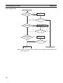
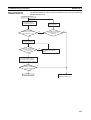
Types of Troubleshooting Information . . . . . . . . . . . . . . . . . . . . . . . . . . . . . . . . . . . . . . . . .
Error Log. . . . . . . . . . . . . . . . . . . . . . . . . . . . . . . . . . . . . . . . . . . . . . . . . . . . . . . . . . . . . . . .
Troubleshooting Tables . . . . . . . . . . . . . . . . . . . . . . . . . . . . . . . . . . . . . . . . . . . . . . . . . . . . .
User-defined Errors . . . . . . . . . . . . . . . . . . . . . . . . . . . . . . . . . . . . . . . . . . . . . . . . . . . . . . . .
Troubleshooting Flowcharts . . . . . . . . . . . . . . . . . . . . . . . . . . . . . . . . . . . . . . . . . . . . . . . . .
204
204
206
212
213
Appendix
A
Precautions when Using the CX-Programmer . . . . . . . . . . . . . . . . . . . . . . . . . . . . . . . . . . .
221
Index . . . . . . . . . . . . . . . . . . . . . . . . . . . . . . . . . . . . . . . . . . . . 225
Revision History . . . . . . . . . . . . . . . . . . . . . . . . . . . . . . . . . . . 231
viii
About this Manual:
This manual describes the installation and operation of the CS1W-HIO01-V1, CS1W-HCP22-V1,
CS1W-HCA22-V1 and CS1W-HCA12-V1 Customizable Counter Units and includes the sections
described below. The Customizable Counter Units provide both normal contact I/O with special I/O
as ideal control capabilities for many applications. The Customizable Counter Units are classified
as CS-series Special I/O Units.
Please read this manual and all other manuals for the Customizable Counter Units listed below
carefully and be sure you understand the information provided before attempting to install or operate a Customizable Counter Unit.
Manual
CS1W-HIO01-V1/HCP22-V1/
HCA22-V1/HCA12-V1
Customizable Counter Units
Operation Manual
(this manual)
Cat. No.
W378
Contents
Describes the hardware and software operation of the Customizable Counter Units.
CS1W-HIO01-V1/HCP22-V1/
HCA22-V1/HCA12-V1
Customizable Counter Units
Programming Manual
SYSMAC WS02-CX-@@-EV3
CX-Programmer
User Manual
W384
Describes the memory areas and programming instructions
of the Customizable Counter Units.
W414
Provide information on how to use the CX-Programmer, a
Windows-based Programming Device that supports the
CQM1H-series PLCs.
CQM1H Series
Programmable Controllers
Operation Manual
W363
Describes Programming Console operations that can be
used connected to the Customizable Counter Units.
Section 1 describes the features of the Customizable Counter Units and the devices required in
an extended system configuration.
Section 2 provides performance specifications and I/O specifications for the Customizable
Counter Unit.
Section 3 provides the names of the different components of the Customizable Counter Unit and
explains the procedures required for installing and wiring the Unit.
Section 4 provides details on the way in which data is exchanged between the Customizable
Counter Unit and the CPU Unit.
Section 5 provides details on the settings made using the Unit Setup Area in the Customizable
Counter Unit.
Section 6 provides details of the settings made using the I/O memory areas in the Customizable
Counter Unit.
Section 7 provides information on interrupts, pulse inputs, pulse outputs, and analog outputs.
Section 8 explains the internal processing of the Customizable Counter Unit, and the time
required for processing and execution.
Section 9 provides information on troubleshooting errors that can occur with the Customizable
Counter Unit.
The Appendix provides precautions required when programming or monitoring the Customizable
Counter Unit with the CX-Programmer.
ix
!WARNING Failure to read and understand the information provided in this manual may result in personal injury or death, damage to the product, or product failure. Please read each section
in its entirety and be sure you understand the information provided in the section and
related sections before attempting any of the procedures or operations given.
x
PRECAUTIONS
This section provides general precautions for using the CS1W-HIO01-V1, CS1W-HCP22-V1, CS1W-HCA22-V1 and
CS1W-HCA12-V1 Customizable Counter Units.
The information contained in this section is important for the safe and reliable application of the Customizable
Counter Units. You must read this section and understand the information contained before attempting to set
up or operate a Customizable Counter Unit.
1
Intended Audience . . . . . . . . . . . . . . . . . . . . . . . . . . . . . . . . . . . . . . . . . . . . .
xii
2
General Precautions . . . . . . . . . . . . . . . . . . . . . . . . . . . . . . . . . . . . . . . . . . . .
xii
3
Safety Precautions . . . . . . . . . . . . . . . . . . . . . . . . . . . . . . . . . . . . . . . . . . . . .
xii
4
Operating Environment Precautions. . . . . . . . . . . . . . . . . . . . . . . . . . . . . . . .
xiii
5
Application Precautions . . . . . . . . . . . . . . . . . . . . . . . . . . . . . . . . . . . . . . . . .
xiv
6
Data Backup . . . . . . . . . . . . . . . . . . . . . . . . . . . . . . . . . . . . . . . . . . . . . . . . . .
xvi
7
6-1
Automatic Backup . . . . . . . . . . . . . . . . . . . . . . . . . . . . . . . . . . . . . .
xvi
6-2
User Programming . . . . . . . . . . . . . . . . . . . . . . . . . . . . . . . . . . . . . .
xvii
6-3
Backing Up DM Area to Flash Memory . . . . . . . . . . . . . . . . . . . . .
xviii
Conformance to EC Directives. . . . . . . . . . . . . . . . . . . . . . . . . . . . . . . . . . . .
xviii
7-1
Applicable Directives. . . . . . . . . . . . . . . . . . . . . . . . . . . . . . . . . . . .
xviii
7-2
Concepts. . . . . . . . . . . . . . . . . . . . . . . . . . . . . . . . . . . . . . . . . . . . . .
xviii
7-3
Conformance to EC Directives . . . . . . . . . . . . . . . . . . . . . . . . . . . .
xix
xi
1
Intended Audience
1
Intended Audience
This manual is intended for the following personnel, who must also have
knowledge of electrical systems (an electrical engineer or the equivalent).
• Personnel in charge of installing FA systems.
• Personnel in charge of designing FA systems.
• Personnel in charge of managing FA systems and facilities.
2
General Precautions
The user must operate the product according to the performance specifications described in the operation manuals.
Before using the product under conditions which are not described in the
manual or applying the product to nuclear control systems, railroad systems,
aviation systems, vehicles, combustion systems, medical equipment, amusement machines, safety equipment, and other systems, machines, and equipment that may have a serious influence on lives and property if used
improperly, consult your OMRON representative.
Make sure that the ratings and performance characteristics of the product are
sufficient for the systems, machines, and equipment, and be sure to provide
the systems, machines, and equipment with double safety mechanisms.
This manual provides information for programming and operating the Unit. Be
sure to read this manual before attempting to use the Unit and keep this manual close at hand for reference during operation.
!WARNING It is extremely important that a PLC and all PLC Units be used for the specified purpose and under the specified conditions, especially in applications that
can directly or indirectly affect human life. You must consult with your OMRON
representative before applying a PLC System to the above-mentioned applications.
3
Safety Precautions
!WARNING Do not attempt to take any Unit apart while the power is being supplied. Doing
so may result in electric shock.
!WARNING Do not touch any of the terminals or terminal blocks while the power is being
supplied. Doing so may result in electric shock.
!WARNING Do not attempt to disassemble, repair, or modify any Units. Any attempt to do
so may result in malfunction, fire, or electric shock.
!WARNING Do not touch the Power Supply Unit while power is being supplied or immediately after power has been turned OFF. Doing so may result in electric shock.
!WARNING Provide safety measures in external circuits, i.e., not in the Programmable
Controller (CPU Unit including associated Units; referred to as “PLC”), in
order to ensure safety in the system if an abnormality occurs due to malfunction of the PLC or another external factor affecting the PLC operation. Not
doing so may result in serious accidents.
xii
Operating Environment Precautions
4
• Emergency stop circuits, interlock circuits, limit circuits, and similar safety
measures must be provided in external control circuits.
• The PLC will turn OFF all outputs when its self-diagnosis function detects
any error or when a severe failure alarm (FALS) instruction is executed.
As a countermeasure for such errors, external safety measures must be
provided to ensure safety in the system.
• The PLC outputs may remain ON or OFF due to deposition or burning of
the output relays or destruction of the output transistors. As a countermeasure for such problems, external safety measures must be provided
to ensure safety in the system.
• When the 24-VDC output (service power supply to the PLC) is overloaded
or short-circuited, the voltage may drop and result in the outputs being
turned OFF. As a countermeasure for such problems, external safety
measures must be provided to ensure safety in the system.
!Caution Execute online edit only after confirming that no adverse effects will be
caused by extending the cycle time. Otherwise, the input signals may not be
readable.
!Caution Confirm safety at the destination node before transferring a program to
another node or changing contents of the I/O memory area. Doing either of
these without confirming safety may result in injury.
!Caution Tighten the screws on the terminal block of the AC power supply to the torque
specified in the operation manual. The loose screws may result in burning or
malfunction.
4
Operating Environment Precautions
!Caution Do not operate the control system in the following locations:
• Locations subject to direct sunlight.
• Locations subject to temperatures or humidity outside the range specified
in the specifications.
• Locations subject to condensation as the result of severe changes in temperature.
• Locations subject to corrosive or flammable gases.
• Locations subject to dust (especially iron dust) or salts.
• Locations subject to exposure to water, oil, or chemicals.
• Locations subject to shock or vibration.
!Caution Take appropriate and sufficient countermeasures when installing systems in
the following locations:
• Locations subject to static electricity or other forms of noise.
• Locations subject to strong electromagnetic fields.
• Locations subject to possible exposure to radioactivity.
• Locations close to power supplies.
xiii
5
Application Precautions
!Caution The operating environment of the PLC System can have a large effect on the
longevity and reliability of the system. Improper operating environments can
lead to malfunction, failure, and other unforeseeable problems with the PLC
System. Be sure that the operating environment is within the specified conditions at installation and remains within the specified conditions during the life
of the system.
5
Application Precautions
!WARNING Always heed these precautions. Failure to abide by the following precautions
could lead to serious or possibly fatal injury.
• Always connect to a ground of 100 W or less when installing the Units. Not
connecting to a ground of 100 W or less may result in electric shock.
• A ground of 100 W or less must be installed when shorting the GR and LG
terminals on the Power Supply Unit.
• Always turn OFF the power supply to the PLC before attempting any of
the following. Not turning OFF the power supply may result in malfunction
or electric shock.
• Mounting or dismounting Power Supply Units, I/O Units, CPU Units, Inner Boards, or any other Units.
• Assembling the Units.
• Setting DIP switches or rotary switches.
• Connecting cables or wiring the system.
• Connecting or disconnecting the connectors.
!Caution Failure to abide by the following precautions could lead to faulty operation of
the PLC or the system, or could damage the PLC or PLC Units. Always heed
these precautions.
• Always turn ON power to the PLC before turning ON power to the control
system. If the PLC power supply is turned ON after the control power supply, temporary errors may result in control system signals because the
output terminals on DC Output Units and other Units will momentarily turn
ON when power is turned ON to the PLC.
• Fail-safe measures must be taken by the customer to ensure safety in the
event that outputs from Output Units remain ON as a result of internal circuit failures, which can occur in relays, transistors, and other elements.
• Fail-safe measures must be taken by the customer to ensure safety in the
event of incorrect, missing, or abnormal signals caused by broken signal
lines, momentary power interruptions, or other causes.
• Interlock circuits, limit circuits, and similar safety measures in external circuits (i.e., not in the Programmable Controller) must be provided by the
customer.
• Always use the power supply voltages specified in the operation manuals.
An incorrect voltage may result in malfunction or burning.
• Take appropriate measures to ensure that the specified power with the
rated voltage and frequency is supplied in places where the power supply
is unstable. An incorrect power supply may result in malfunction.
xiv
5
Application Precautions
• Install external breakers and take other safety measures against short-circuiting in external wiring. Insufficient safety measures against short-circuiting may result in burning.
• Do not apply voltages to the Input Units in excess of the rated input voltage. Excess voltages may result in burning.
• Do not apply voltages or connect loads to the Output Units in excess of
the maximum switching capacity. Excess voltage or loads may result in
burning.
• Disconnect the functional ground terminal when performing withstand
voltage tests. Not disconnecting the functional ground terminal may result
in burning.
• Install the Units properly as specified in the operation manuals. Improper
installation of the Units may result in malfunction.
• Be sure that all the mounting screws, terminal screws, and cable connector screws are tightened to the torque specified in the relevant manuals.
Incorrect tightening torque may result in malfunction.
• Leave the label attached to the Unit when wiring. Removing the label may
result in malfunction if foreign matter enters the Unit.
• Remove the label after the completion of wiring to ensure proper heat dissipation. Leaving the label attached may result in malfunction.
• Use crimp terminals for wiring. Do not connect bare stranded wires
directly to terminals. Connection of bare stranded wires may result in
burning.
• Wire all connections correctly.
• Double-check all wiring and switch settings before turning ON the power
supply. Incorrect wiring may result in burning.
• Mount Units only after checking terminal blocks and connectors completely.
• Be sure that the terminal blocks, Memory Units, expansion cables, and
other items with locking devices are properly locked into place. Improper
locking may result in malfunction.
• Check switch settings, the contents of the DM Area, and other preparations before starting operation. Starting operation without the proper settings or data may result in an unexpected operation.
• Check the user program for proper execution before actually running it on
the Unit. Not checking the program may result in an unexpected operation.
• Confirm that no adverse effect will occur in the system before attempting
any of the following. Not doing so may result in an unexpected operation.
• Changing the operating mode of the PLC.
• Force-setting/force-resetting any bit in memory.
• Changing the present value of any word or any set value in memory.
• Resume operation only after transferring to the new CPU Unit the contents of the DM Area, HR Area, and other data required for resuming
operation. Not doing so may result in an unexpected operation.
• Do not pull on the cables or bend the cables beyond their natural limit.
Doing either of these may break the cables.
• Do not place objects on top of the cables or other wiring lines. Doing so
may break the cables.
xv
6
Data Backup
• When replacing parts, be sure to confirm that the rating of a new part is
correct. Not doing so may result in malfunction or burning.
• Before touching a Unit, be sure to first touch a grounded metallic object in
order to discharge any static build-up. Not doing so may result in malfunction or damage.
• When transporting or storing circuit boards, cover them in antistatic material to protect them from static electricity and maintain the proper storage
temperature.
• Do not touch circuit boards or the components mounted to them with your
bare hands. There are sharp leads and other parts on the boards that
may cause injury if handled improperly.
• Data in the DM Area, error log, EM Area, or Timer/Counter Area may
become corrupted if power is not supplied for an extended period of time.
Program the PLC to check SR 24914 before starting operation. If SR
24914 is ON, the memory areas that are normally held during power interruptions will not have been held properly (i.e., the data will be corrupted).
(The data in the DM Area can be backed up to flash memory by turning
ON SR 25200.)
6
6-1
Data Backup
Automatic Backup
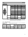
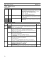
Data in the Customizable Counter Units is backed up either by a super capacitor or flash memory, as listed in the following table.
Data
DM Area (DM 0000 to DM 6143), EM Area (EM 0000 to EM
2047), error log (DM 6144 to DM 6199), and counter present
values.
A setting is provided to either enable or disable holding EM
Area data. The default is to not hold the data.
Data backup
RAM with super
capacitor
User program, read-only DM Area words (DM 6200 to DM
6599), Unit Setup Area (DM 6600 to DM 6655), expansion
instructions information, read/write DM Area words (DM 0000
to DM 6143, see note.)
Flash memory
Note The contents of DM 0000 to DM 6143 are written to flash memory only when
SR 25200 (DM Area Backup Bit) is turned ON.
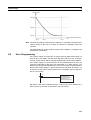
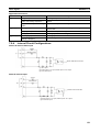
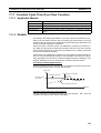
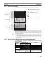
The data in RAM is backed up by the super capacitor for 10 days at 25°C. The
backup time varies with the ambient temperature as shown in the following
graph.
xvi
6
Data Backup
Backup time
10th day
5th day
1st day
Ambient temperature
25°C
40°C
75°C
Note The times give above assume that the capacitor is completely charged. Power
must be supply to the Unit for at least 15 minutes to completely charge the
capacitor.
The data backed up by the capacitor will become unstable or corrupted if the
backup time is exceeded.
6-2
User Programming
If the power supply is turned OFF for longer than the data backup time (10
days at 25°C), the data in the DM Area, EM Area, and Error Log, as well as
counter present values, will be lost and any data that is read will be unstable.
If the power supply is to be turned OFF for an extended period of time, the
contents of DM 0000 to DM 6143 can be backed up in flash memory. The
Backup Data Corrupted Flag (SR 24914) can also be used as shown below to
detect when backup data (i.e., data in the DM Area, EM Area, and Error Log,
as well as counter present values) has become corrupted to perform appropriate error processing.
24914
Processing for
corruption of data
backed up for
power interruptions
DM 0000 to DM 6143 (read/write portion of DM Area) can be backed up in
flash memory by the user as described in the next section.
xvii
7
Conformance to EC Directives
6-3
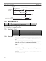
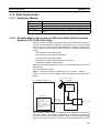
Backing Up DM Area to Flash Memory
The contents of DM 0000 to DM 6143 can be written to flash memory by turning ON SR 25200 (DM Flash Memory Backup Bit) in PROGRAM mode.
(SR 25200 will turn OFF automatically when transfer has been completed.)
The data stored in flash memory can be read back to DM 0000 to DM 6143 by
using the XFER(70) instruction as shown below.
Execution
condition
MOV(21)
#0100
LR00
MOV(21)
#0000
LR01
@XFER(70)
#9999
LR00
DM0000
25503
ER Flag
7
7-1
Conformance to EC Directives
Applicable Directives
• EMC Directives
• Low Voltage Directive
7-2
Concepts
EMC Directives
OMRON devices that comply with EC Directives also conform to the related
EMC standards so that they can be more easily built into other devices or
machines. The actual products have been checked for conformity to EMC
standards (see the following note). Whether the products conform to the standards in the system used by the customer, however, must be checked by the
customer.
EMC-related performance of the OMRON devices that comply with EC Directives will vary depending on the configuration, wiring, and other conditions of
the equipment or control panel in which the OMRON devices are installed.
The customer must, therefore, perform final checks to confirm that devices
and the overall machine conform to EMC standards.
Note Applicable EMC (Electromagnetic Compatibility) standards are as follows:
EMS (Electromagnetic Susceptibility): EN61000-6-2
EMI (Electromagnetic Interference):
EN50081-2
(Radiated emission: 10-m regulations)
Low Voltage Directive
Always ensure that devices operating at voltages of 50 to 1,000 VAC or 75 to
1,500 VDC meet the required safety standards for the PLC (EN61131-2).
xviii
7
Conformance to EC Directives
7-3
Conformance to EC Directives
The CS1W-HIO01-V1, CS1W-HCP22-V1, CS1W-HCA22-V1 and CS1WHCA12-V1 Customizable Counter Units comply with EC Directives. To ensure
that the machine or device in which the Customizable Counter Unit is used
complies with EC directives, the Unit must be installed as follows:
1,2,3...
1. The Customizable Counter Unit must be installed within a control panel.
2. Reinforced insulation or double insulation must be used for the Customizable Counter Unit DC power supplies used for the communications and
I/O power supplies.
3. The Customizable Counter Units complying with EC Directives also conform to the Common Emission Standard (EN50081-2). When a Customizable Counter Unit is built into a machine, however, changes can occur,
particularly for the radiated emission (10-m regulations), due to the structure of the machine, other connected devices, wiring, etc. The customer
must, therefore, perform final checks to confirm that devices and the overall machine using a Customizable Counter Unit conform to EC standards.
xix
Conformance to EC Directives
xx
7
SECTION 1
Features and System Configuration
This section describes the features of the Customizable Counter Units and the devices required in an extended system
configuration.
1-1
1-2
Outline . . . . . . . . . . . . . . . . . . . . . . . . . . . . . . . . . . . . . . . . . . . . . . . . . . . . . .
2
1-1-1
Outline . . . . . . . . . . . . . . . . . . . . . . . . . . . . . . . . . . . . . . . . . . . . . . .
2
1-1-2
Features . . . . . . . . . . . . . . . . . . . . . . . . . . . . . . . . . . . . . . . . . . . . . .
5
1-1-3
Application Examples . . . . . . . . . . . . . . . . . . . . . . . . . . . . . . . . . . .
7
Models and System Configurations . . . . . . . . . . . . . . . . . . . . . . . . . . . . . . . .
14
1-2-1
Models . . . . . . . . . . . . . . . . . . . . . . . . . . . . . . . . . . . . . . . . . . . . . . .
14
1-2-2
System Configurations . . . . . . . . . . . . . . . . . . . . . . . . . . . . . . . . . . .
14
1
Section 1-1
Outline
1-1
1-1-1
Outline
Outline
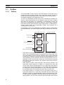
The Customizable Counter Units are CS-series Special I/O Units that can be
programmed using a ladder program and provide both standard contact I/O
and special I/O (including pulse inputs, pulse outputs, and analog outputs).
(I/O support depends on the model of the Unit.)
The I/O of a Customizable Counter Unit can be controlled by the ladder program in it without intervention from the program in the CPU Unit to achieve
high-speed I/O processing. By customizing a Customizable Counter Unit
using its I/O, programming, and interrupt functions, a wide range of applications requiring high-speed response can be implemented in a distributed processing system where the Customizable Counter Unit functions as a
coprocessor for the CPU Unit.
Customizable Counter Unit capabilities also facilitate machine modularization
and standardization, and make machine and device maintenance much easier.
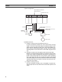
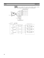
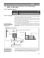
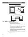
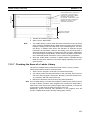
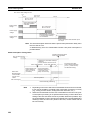
Customizable Counter Unit
Normal inputs
CS-series CPU Unit
Input data
Pulse inputs
High-speed control loop
Normal outputs
Ladder
program
Data exchange
with the CPU Unit
Output data
Pulse or analog outputs
• High-speed I/O processing is enabled by the small-capacity ladder program in the Customizable Counter Unit that achieves a high-speed cycle.
The Customizable Counter Unit also supports various types of interrupt
programming, enabling it to handle special high-speed applications previously handled by sensor controllers and microcomputer boards. The Customizable Counter Unit can also perform part of the functions previously
performed by High-speed Counter Units, Position Control Units, and Analog Output Units.
• Other features include normal interrupts, interval timer interrupts, and
high-speed counter interrupts, in addition to a high-precision timer that
uses a pulse counter (CS1W-HCP22-V1 only), target value interrupts for
a pulse output value (CS1W-HCP22-V1 only), analog output instructions
for analog slope control (CS1W-HCA22-V1 only), and range comparisons
for the present value of a high-precision pulse output counter timer.
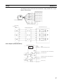
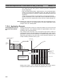
• The CS1W-HCA12-V1 is a special I/O unit of CS-series, having all of 1
high-speed analog input, 1 pulse input (compatible with servo drivers with
absolute encoders), 2 high-speed analog outputs, and operations by builtin ladder program (simplified positioning, discriminant and counting processes) within 1 unit. The unit by itself can process both the "linear sensor
2
Outline
Section 1-1
control" and "simplified position/speed control", which have been processed separately by the dedicated unit or system in existing models.
1) High-speed input of analog signals from displacement sensors etc,
which have been processed in the linear sensor controller in the existing system, enables the ladder program processing.
2) This unit can perform the simplified position controls that have been
operated with motion control and position control units in the existing
system. Taking in the encoder signals enables the unit to drive the servo driver with analog output. In addition, using the other analog output
makes it possible to limit the torque and control inverters.
3
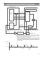
Section 1-1
Outline
High-speed input of analog signals from
displacement sensors etc.
Control the servo by the high-speed analog
output
Analog Output Unit
Motion Control Unit
Basic I/O Unit
CPU Unit
programs
contact input
Analog
Linear sensor
control
Analog output
output
(limit the torque) (speed
discrimination
Position information
(Absolute encoder
output)
control)
4 to 20 mA
Displacement sensors
Pressure sensors
Absolute encoders
servo driver
Integrate
Customizable Counter Units
High-speed analog input is
possible.
it is possible to take in the
output data directly from the
displacement sensors or the
pressure sensors etc.
Analog
output
Analog output
(speed
(limit the torque) control)
4 to 20 mA
It is possible to
encapsulate the
programs as the
ladder library.
Position information
(Absolute encoder output)
Absolute encoders
servo driver
High-speed analog input
Simplified position control
• On the models with "V1" at the rightmost 2 digits, all or a part (subroutine)
of the ladder programs in the unit are encapsulated and stored in the
Flash memory, also provided in the unit. The real customization is made
possible.
4
Section 1-1
Outline
1-1-2
Features
Programmable I/O Control
• The program capacity for the ladder program in the Customizable Counter
Unit is 4 Kwords.
• Standard features include 12 contact inputs and 8 contact outputs.
• For special I/O, the CS1W-HCP22-V1 provides 2 pulse inputs and 2 pulse
outputs, while the CS1W-HCA22-V1 provides 2 pulse inputs and 2 analog
outputs.
• Pulse inputs on the CS1W-HCP22-V1 and CS1W-HCA22-V1 can be used
for a high-speed counter (50 or 200 kHz, signal phase), and the present
value of the counter can be used to create target value interrupts or range
comparison bit pattern outputs. Trapezoid pulse (speed) outputs or conditional ON/OFF outputs can thus be created for the present value pulse
input. Furthermore, an Electronic Cam Mode can be used to change the
pulse output value for absolute positioning or the pulse output frequency
for speed control in response to the present value of the pulse input (e.g.,
for a rotational angle). You can also monitor changes in the present value
of the high-speed counter or measure the frequency from the present
value of the high-speed counter.
• Pulse outputs on the CS1W-HCP22-V1 can be used for specified frequency outputs with or without acceleration/deceleration, as well as for
one-shot outputs (turned ON for a specified time between 0.01 and
9,999 ms). The one-shot pulse output function can also be used to
achieve a high-precision pulse counter timer with a minimum time of
0.01 ms, and the present value can be used to create target value interrupts or range comparison bit pattern outputs. Trapezoid pulse (speed)
outputs or conditional ON/OFF outputs can thus be created for the
present value of the pulse output.
• Analog outputs on the CS1W-HCA22-V1 can be used with the SPED or
ACC instruction to step analog outputs or for rising or falling sloped outputs.
• Combinations with timer instructions enable time-stepped or trapezoid
analog outputs.
• Analog outputs can be set to be held at the peak, current, or cleared
value by turning OFF an Output Conversion Enable Bit when required
or for errors.
• The SPED and ACC instructions can be used to control the analog output value independent of the END refresh.
• The I/O refresh time can be reduced by disabling the analog outputs
when they are not required.
• Rate-of-change measurements are possible at a sampling time for the
high-speed counter input.
• High-speed counter input frequency measurements can be taken.
• The present value of the high-speed counters can be cleared or held
when power is turned ON.
• The high-speed counters can be started and started by controlling the
status of a control bit.
• Any of four pulse output ranges can be specified: 6 Hz to 20 kHz, 25 Hz to
50 kHz, 100 Hz to 100 kHz, or 400 Hz to 200 kHz.
• The present value of the pulse output can be reset.
5
Outline
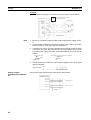
Advanced Processing
Section 1-1
• Either high-speed or normal-speed execution can be selected for basic
instructions. The execution time for basic instructions in High-speed Execution Mode is approximately twice as fast as the time in Normal Execution Mode. (The program must be approximately 1 Kword or less to use
High-speed Execution Mode.) (Example for LD instruction: Normal Execution: 0.4 ms; High-speed Execution: 0.2 ms)
• Faster execution of CTBL and other instructions using table data can be
achieved by not holding the EM Area status when power is turned OFF.
Coordinating Operation
with the CPU Unit
• Data can be exchanged in three different areas of memory shared with
the CPU Unit to perform handshaking and other operations without programming a special interface.
• Ten words of the CIO Area in the CPU Unit are shared with SR Area
Words in the Customizable Counter Unit.
• Up to 90 words of the DM Area in the CPU Unit can be shared with
user-set words in the Customizable Counter Unit.
• Up to 32 user-set words in the CPU Unit can be shared with LR Area
words in the Customizable Counter Unit.
• External interrupt tasks in the CPU Unit can be executed by programming
the MCRO instruction in the Customizable Counter Unit. The Customizable Counter Unit can thus activate programming in the CPU Unit
depending on the control status of the Customizable Counter Unit to synchronize processing with other Units.
Special I/Os that Can
Support Various
Applications
• 1 high-speed analog input (CS1W-HCA12-V1)
High-speed analog input (A/D conversion time = 50 ms) is possible. It supports 0 to 10 V, 1 to 5 V, -10 to 10 V, 0 to 5 V, and 4 to 20 mA. This
enables the control supporting the analog input from the displacement
and pressure sensors through the linear sensor.
• 2 high-speed analog outputs (CS1W-HCA12-V1)
High-speed analog output (D/A conversion time = 50 ms) is possible. It
supports 0 to 10 V, 1 to 5 V, -10 to 10 V, 0 to 5 V. The combination of this
and the use of servo drivers of an analog input type enables the speed
control, torque commands, etc. in addition, it can be used for the inverter
control (frequency commands).
• 1 input for taking in the absolute encoder output data (CS1W-HCP22-V1/
HCA22-V1/HCA12-V1)
With this input, it is possible to take in the absolute encoder output data
directly from the servo drivers manufactured by OMRON, etc. Since it
enables the feedback input of the absolute value information, the analog
output mentioned above can be used for position control.
Ladder Library Function
(All -V1 Models)
These units has the built-in ladder programs. It is possible to encapsulate the
programs as the ladder library. The ladder library is saved to the Flash memory in the unit. The encapsulation of the programs to the library enables the
"protection of the ladder software assets from the third party" and "execution
of the ladder software functions quasi-without programming".
Back-up Function (All -V1
Models)
Through the bit manipulation from the CPU unit, it is possible to back up
(write) or restore (read) the data of the unit to or from the memory card. With
the use of CS1-H CPU units, the data can be backed up or restored through
the simplified back-up operation on the front panel of the CPU unit.
6
Section 1-1
Outline
1-1-3
Application Examples
The following are a few examples of the types of applications that are possible
by combining various features.
• Contact Input ® Programming ® Contact Output:
High-speed interrupt I/O processing or IORF instruction execution can be
used to refresh outputs whenever required.
• Pulse Input ® Program ® Pulse Output for CS1W-HCP22-V1
• An Electronic Cam Mode can be used to perform a specific absolute
positioning operation and speed change for the rotational angle or current position of a workpiece. For example, the encoder output from a
main control axis can be input to the high-speed counter, and a specified movement for a target position (number of output pulses) for the
followup axis can be defined using linear approximation with the APR
instruction. The PULS instruction can also be used to change the number of output pulses (target position) based on the defined value to
change the pulse output during operation.
• Speed control via a pulse output can be achieved in response to the
position of a workpiece. The present value of either a high-speed
counter or pulse output can be used with a target value interrupt for an
interrupt program that contains an instruction to change the frequency,
i.e., SPED or ACC.
• High-speed processing, such as for coating or valve control, can be
achieved for a fast-moving object by outputting a one-shot output pulse
with a minimum unit of 0.01 ms from a specified position. This is
achieved by combining an interrupt for the present value of a pulse input, and then programming a one-shot pulse output using the STIM instruction in the interrupt program.
• Pulse Input ® Program ® Analog Output for CS1W-HCA22-V1
• Simple positioning with an analog output can be achieved with an inverter and motor. This is achieved by combining an interrupt for the
present value of a pulse input, and then programming a stepped analog output using the SPED instruction or a slopped analog output using
the ACC instruction in the interrupt program.
• Trapezoid torque control with an analog output for the position of a
workpiece. This is achieved by combining an interrupt for the present
value of a pulse input, and then programming a slopped analog output
using the ACC instruction in the interrupt program.
• Trapezoid analog output for a specified time can be achieved by combining a timer instruction with a slopped analog output using the ACC
instruction.
• Torque control (Clamping in molding applications, transfer control in injection-molding applications) (CS1W-HCA12-V1 only) ® Position control ®
pressure control (speed control and torque limit) ® position control
• Using this unit with a servo driver of an analog input type and a pressure sensor enables the control as described below. Note that the servo driver (W series manufactured by OMRON in the example) is to be
in the "speed control" mode.
7
Section 1-1
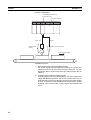
Outline
• System configuration
Customizable Counter Unit
CS1W-HCA12-V1
CS-series CPU Unit
ON/OFF
Analog input
(4 to 20 mA)
Position
detector
Analog output (−10 to +10 V):
Speed control
Analog output (0 to 10 V):
Torque limit)
Signal from
absolute encoder
Pressure
sensor
Servo driver
Servo motor
• Operation Process
1) Position control by the unit (CS1W-HCA12-V1):
A speed command is issued to the servo driver with the analog
output. The servo driver feeds back the absolute position information with the absolute encoder input. Using the feedback, position control is executed (through the speed command output)
following SPED or ACC instructions on the ladder program of the
unit.
2) Pressure control by the unit (speed control and torque limit):
Reaching a certain position (position for pressure control) causes the unit to output a speed and a torque limit command for the
speed control and torque limit. The pressure control (clamping
etc) is executed after the unit converts the analog inputs (load
cell, strain gauge, etc) from the pressure sensor to the analog
outputs (torque limit by the speed command and torque limit output) for the servo driver.
3) Position control by the unit
Once the operation (molding, etc) is completed, a speed command output from the unit returns the mechanical system to its
origin.
8
Section 1-1
Outline
Customizable Counter Unit
CS1W-HCA12-V1
Servo driver (Omron W-series)
Control mode:
Speed control (analog commands)
Position control,
or
Speed control
(SPED or ACC
instruction)
Analog output
(Speed control)
switch
−10 to 10 V, etc.
Speed control
SEN signal
Signal from
ABS encoder
Pressure
control
+
Analog output
(Torque limit)
Torque limit
−10 to 10 V, etc.
Absolute encoder signal
(line driver)
Analog input
Power cable
(U, V, W)
Pressure
sensor
4 to 20 mA,
0 to 10 V etc.
Clamping
in pressing
Servo motor
with Absolute encoder
• Linear sensor control (control based on monitoring the ups and downs/
distortion/thickness/height/diameter of objects) (CS1W-HCA12-V1 only)
• Example) Counting ups and downs (piles)
With the use of a displacement sensor, the unit can count the number
of ups and downs (piles) by monitoring the change in the displacement
amount as the sensor measures them on the surface of objects moving at high speed.
Displacement
Count
1
2
3
4
Threshold
Time
9
Section 1-1
Outline
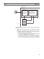
• System configuration
Customizable Counter Unit
CS1W-HCA12-V1
CS-series CPU Unit
4 to 20 mA
Displacement
Sensor
ON/OFF
Photo-electric Switches
Moving at high speed
• Operation Process
1) High-speed analog input (immediate refresh)
4 to 20 mA signals from the displacement sensor are input to and
refreshed in the unit at every PRV instruction execution. The displacement data is stored in the areas (Ex: DM) that have the I/O
memory.
2) Counting process with the ladder program
A ladder program has to be arranged (Ex: The unit compares the
ranges with BCMP instruction, and the unit counts rises of the results with INC instruction) so that the counter will count the number
of times of when the stored displacement data exceed a certain
threshold value. The execution of the program will make the unit
count.
10
Section 1-1
Outline
Customizable Counter Unit
CS1W-HCA12-V1
Ladder program
Displacement
Sensor
4 to 20 mA
Acquire the analog
input value by PRV
instruction (immediate refresh)
I/O memory
The unit compares the
ranges with BCMP
instruction, and the unit
counts rises of the results
with INC instruction
Store
Displacement
Count value
• Linear sensor control (High-speed trace of in-line quality data) (CS1WHCA12-V1 only)
• Example) Quality check of high-speed assembling process (injection
etc)
With the use of a displacement sensor, the sensor inputs the characteristic data of objects flowing at high speed, and the unit' data memory stores the input data at constant intervals.
a) The data can be transferred to the memory card by batch processing, and can be read using the PC for analyses.
b) The data can be transferred to the CPU unit's data memory by
batch processing, and the line plot of the data can be displayed on
the screen of the programmable terminal (NS series by OMRON).
11
Section 1-1
Outline
• System configuration
NS series PT
Customizable Counter Unit
CS1W-HCA12-V1
CS-series CPU Unit
Memory card
Store the line plot
Analyze
4 to 20 mA
Injection
Process
Displacement
Sensor
ON/OFF
Photo-electric Switches
Moving at high speed
12
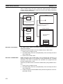
Personal computer
Section 1-1
Outline
• Operation Process
1) High-speed analog input by scheduled interrupts with the ladder
program (immediate refresh)
The PRV instruction is executed at each of constant executions of
subroutine programs with the scheduled interrupts (interval timer).
4 to 20 mA signals from the displacement sensor are input, refreshed, and stored (trace data) in the I/O memory area (Ex. DM)
of the main unit.
2) Transferring the traced data to the CPU unit
The data traced in the unit is transferred to the CPU unit. (Ex.
Through the cyclic transfer to DM allocated in the CPU unit)
3) Transferring the data to the memory card inserted in the slot of the
CPU unit
The data in the DM area is stored in the memory card as a data
file (.CSV etc) through the FWRIT instruction of the CPU unit.
4) Analysis performed on the spreadsheet software
Through the memory card adaptor connected to the PC, the data
file (.CSV etc) can be analyzed on the spreadsheet software.
5) Line plot displayed on PT (NS series)
The trace data in the CPU unit can be displayed as the line plot on
PT (NS series).
Customizable Counter Unit
CS1W-HCA12-V1
CS-series CPU Unit
Ladder program
Ladder program
PT (NS series)
Start the interval timer
by STIM instruction
Store the data to
memory card
Display
a line graph
Interrupt subroutines
SBN
Displacement
Sensor
Acquire the analog
input value by PRV
instruction (immediate
refresh)
4 to 20 mA
RET
Store
I/O memory
Traced data
Displacement
value 1
Displacement
value 2
I/O memory
Allocated DM area
Refresh
Store
Memory card
Displacement
value n
13
Section 1-2
Models and System Configurations
1-2
1-2-1
Models and System Configurations
Models
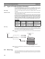
There are three models of Customizable Counter Unit, all of which are classified as CS1 Special I/O Units.
Model number
Functions
CS1W-HIO01-V1
CS1W-HCP22-V1
12 contact inputs, 8 contact outputs
12 contact inputs, 8 contact outputs, 2 pulse inputs, 2 pulse outputs
12 contact inputs, 8 contact outputs, 2 pulse inputs, 2 analog outputs
12 contact inputs, 8 contact outputs, 1 analog input, 1 pulse input
(compatible with servo drivers with absolute encoders), 2 analog
outputs
CS1W-HCA22-V1
CS1W-HCA12-V1
1-2-2
System Configurations
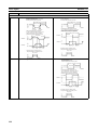
CS1W-HIO01-V1(Basic Model)
Programming
Device
CX-Programmer
Creating, transferring, and
monitoring the program for the
Customizable Counter Unit.
OR
Peripheral Port Connecting Cable
(peripheral bus)
12 contact inputs, 4 of
which can be used as
interrupt inputs
8 contact outputs
14
Contact I/O
CS1W-HIO01-V1
Customizable
Counter Unit
CS-series CPU Unit
Peripheral port
Ladder
program
Ladder
program
I/O
memory
I/O
memory
Programming
Console
Section 1-2
Models and System Configurations
CS1W-HCP22-V1 (Pulse Inputs and Pulse Outputs)
Programming
Device
CX-Programmer
Creating, transferring, and
monitoring the program for
the Customizable Counter
Unit.
OR
Programming
Console
Peripheral Port Connecting Cable
(peripheral bus)
12 contact inputs, 4 of
which can be used as
interrupt inputs
8 contact outputs
(compatible with
servo drivers with
absolute encoders)
CS-series CPU Unit
Peripheral port
Ladder
program
Ladder
program
I/O
memory
I/O
memory
Rotary encoder, etc.
Rotary encoder, etc.
Servodriver, etc.
2 pulse outputs
Special I/O
2 pulse inputs
Contact I/O
CS1W-HCP22-V1
Customizable
Counter Unit
Servodriver, etc.
15
Section 1-2
Models and System Configurations
CS1W-HCA22-V1 (Pulse Inputs and Analog Outputs)
CX-Programmer
Programming
Device
Creating, transferring, and
monitoring the program for
the Customizable Counter
Unit.
OR
Programming
Console
Peripheral Port Connecting Cable
(peripheral bus)
12 contact inputs, 4 of
which can be used as
interrupt inputs
8 contact outputs
Contact I/O
CS1W-HCA22-V1
Customizable
Counter Unit
CS-series CPU Unit
Peripheral port
Ladder
program
Ladder
program
I/O
memory
I/O
memory
(compatible with
servo drivers with
absolute encoders)
Rotary encoder, etc.
Operation
terminal,
etc.
2 analog outputs
Special I/O
Rotary encoder, etc.
2 pulse inputs
Operation
terminal,
etc.
CS1W-HCA12-V1 (Analog Inputs, Pulse Input and Analog Outputs)
CX-Programmer
Programming
Device
Creating, transferring, and
monitoring the program for
the Customizable Counter
Unit.
OR
Peripheral Port Connecting Cable
(peripheral bus)
12 contact inputs, 4 of
which can be used as
interrupt inputs
8 contact outputs
1 pulse inputs
(compatible with
servo drivers with
absolute encoders)
2 analog outputs
16
Sensor inputs
(Pressure,
displacement,
etc.)
Rotary encoder, etc.
Operation
terminal,
etc.
Operation
terminal,
etc.
Special I/O
1 analog inputs
Contact I/O
CS1W-HCA12-V1
Customizable
Counter Unit
CS-series CPU Unit
Peripheral port
Ladder
program
Ladder
program
I/O
memory
I/O
memory
Programming
Console
Section 1-2
Models and System Configurations
Programming Devices
The CX-Programmer versions that can be used with the Customizable
Counter Unit are given in the following table.
Name
CX-Programmer
Ver. 1.2 or later
(on CD-ROM)
Model number
WS02-CXPC1-E
Computer
Serial communications
mode
IBM PC/AT or compatible Peripheral bus
OS: Microsoft Windows
95 or 98
Model setting on the
CX-Programmer
CQM1H-CPU61
Note There are some functional limitations in using the CX-Programmer
with the Customizable Counter Unit. Refer to 3-4 Programming Devices for details.
The Programming Consoles that can be used with the Customizable Counter
Unit are given in the following table.
Model number
C200H-PRO27
Cable
CS1W-CN224 or CS1W-CN624 required separately.
CQM1-PRO01
2-m cable provided with Programming Console, but CS1W-N114
required separately.
2-m cable provided with Programming Console
CQM1H-PRO01
Connecting Contact and Special I/O
Special connectors are required to connect the contact I/O and special I/O to
the connectors on the Customizable Counter Unit. These connectors are provided with the Customizable Counter Unit and can be purchased separately.
The cables for these connectors must be provided and wired to the connectors by the user. An OMRON Connector–Terminal Block Conversion Unit can
also be used for the special I/O. Refer to 3-3 Wiring for details.
17
Models and System Configurations
18
Section 1-2
SECTION 2
Specifications
This section provides performance specifications and I/O specifications for the Customizable Counter Unit.
2-1
2-2
Performance Specifications . . . . . . . . . . . . . . . . . . . . . . . . . . . . . . . . . . . . . .
20
2-1-1
Available Models . . . . . . . . . . . . . . . . . . . . . . . . . . . . . . . . . . . . . . .
20
2-1-2
Specifications . . . . . . . . . . . . . . . . . . . . . . . . . . . . . . . . . . . . . . . . . .
20
2-1-3
Program and Memory . . . . . . . . . . . . . . . . . . . . . . . . . . . . . . . . . . .
22
2-1-4
Functions . . . . . . . . . . . . . . . . . . . . . . . . . . . . . . . . . . . . . . . . . . . . .
25
2-1-5
I/O Specifications. . . . . . . . . . . . . . . . . . . . . . . . . . . . . . . . . . . . . . .
28
Contact I/O Specifications (All Units) . . . . . . . . . . . . . . . . . . . . . . . . . . . . . .
33
2-2-1
Contact I/O Specifications . . . . . . . . . . . . . . . . . . . . . . . . . . . . . . . .
33
2-2-2
I/O Connector Pin Arrangement . . . . . . . . . . . . . . . . . . . . . . . . . . .
34
19
Section 2-1
Performance Specifications
2-1
2-1-1
Performance Specifications
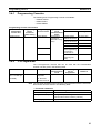
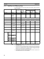
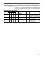
Available Models
Model number
Program
capacity
CS1W-HIO01-V1 4 Kwords
CS1W-HCP22V1
CS1W-HCA22V1
CS1W-HCA12V1
I/O points (built-in)
Contact
Contact
input
output
Pulse input (highspeed counters)
Special I/O
Pulse
Analog Analog
outputs outputs inputs
Compatible
with servo
driver with
absolute
encoder
(See note)
12 inputs 8 transistor None No
None
(24 VDC) outputs
(4 inputs (sinking)
2 pts Yes
2 pts
can be
used as
2 pts Yes
None
interrupt
inputs)
1 pts Yes
None
None
None
None
None
2 pts
None
2 pts
1 pts
Built-in
peripheral
port
For Programming
Console or
CX-Programmer
Note Supported only by lot numbers of 0209__ or higher.
2-1-2
Specifications
Item
Model number
Specification
CS1W-HIO01-V1/CS1W-HCP22-V1/CS1W-HCA22-V1/CS1WHCA12-V1
Unit classification
Applicable PLCs
CS1 Special I/O Unit
CS-series PLCs
Applicable unit numbers
Applicable Rack/slot
00 to 95 (Must not be duplicated with other Special I/O Units)
CS-series CPU Rack or Expansion Rack
Note
Exchange of
specific data
with CPU Unit
Special I/O Unit Area
(CIO n to n+9;
n = 2000 + (unit number ´ 10))
1.
2.
There are no restrictions on the mounting slot.
Mounting to C200H Expansion Racks or SYSMAC
BUS Slave Racks is not possible.
10 words per Unit (data exchanged constantly)
5 words: CPU Unit ® Customizable Counter Unit (RUN/STOP commands, general-purpose output data)
5 words: Customizable Counter Unit ® CPU Unit (Unit status, general-purpose input data)
100 words per Unit
DM Area words allocated to Special I/O Units (m to m+99;
m = D20000 + (unit number ´ 99))
Initial settings
10 words: System Setup Area (transferred from the CPU Unit to the
from the CPU
Customizable Counter Unit at startup or Unit restart).
Unit
The System Setup Area contains the following settings: Enable/disable of RUN/STOP command from the CPU Unit; startup operating
mode; specification of beginning word addresses for the output and
input areas for data exchange with the CPU Unit; number of
exchange words; the area used as the data exchange area in the
Customizable Counter Unit; address specifications, etc.
Area for
90 words: For exchanging the general-purpose data listed below.
exchanging
general-purpose data with
the CPU Unit
20
Section 2-1
Performance Specifications
Exchange of
general-purpose data with
CPU Unit
Item
Continuous data exchange
between words in the SR Area in
the Customizable Counter Unit
and CIO Area allocated words in
the CPU Unit
Specification
4 input words and 4 output words (Inputs are to Customizable
Counter Unit)
I/O refresh is performed between words in the Customizable
Counter Unit’s SR Area (SR 231 to SR 234 and SR 236 to SR 239)
and words allocated in the CPU Unit’s CIO Area.
Continuous data exchange
between user-set words in the
Customizable Counter Unit and
words allocated in the CPU Unit’s
DM Area
90 words max.
I/O refresh is performed for up to 90 words between user-set words
in the Customizable Counter Unit and words allocated in the CPU
Unit’s DM Area.
Continuous data exchange
between LR Area words in the
Customizable Counter Unit and
user-set words in the CPU Unit
Methods for making Customizable Counter Unit’s
initial settings
Mounting method
Setting switches
Display
Front panel
connections
All models
(CS1W-HIO01-V1/HCP22-V1/
HCA22-V1/HCA12-V1)
CS1W-HCP22-V1/HCA22-V1/
HCA12-V1 only
Super-capacitor backup data (in RAM)
Note Both inputs and outputs can be set in Customizable Counter
Unit’s DM, AR, IR, LR, and EM Areas.
32 words max.
I/O refresh is performed for up to 32 words between the Customizable Counter Unit’s LR Area (in the order inputs ® outputs) and
user-set words in the CPU Unit.
Note Both inputs and outputs can be set in CPU Unit’s CIO, WR,
AR, HR, DM, and EM Areas.
1. Using the initial settings in the first 10 words (m to m+9) of the
words allocated in the CPU Unit’s DM Area
2. Using the Unit Setup Area (DM 6600 to DM 6655) of the Customizable Counter Unit
Rack mounting
Rotary switches on front panel: Unit number (0 to 95)
Toggle switch: Programming Device connection switch (enables/disables servicing for the Programming Device connected to the
peripheral port)
25 LED indicators
The Unit is equipped with the following indicators: RUN (Unit operation), OPN (Unit program running), ERC (Unit error), ERH (CPU
Unit error), COMM (peripheral communications), In0 to In11 (for
inputs), and Out0 to Out7 (for outputs).
• One peripheral port (for Programming Device)
• One I/O connector (Compatible connector: FCN-361J024-AU
(socket) and FCN-360C024-J2 (connector cover) made by
Fujitsu)
In addition to the above, one special I/O connector (Compatible connector: FCN-361J040-AU (socket) and FCN-360C040-J2 (connector cover) made by Fujitsu)
DM Area (DM 0000 to DM 6143), EM Area (EM 0000 to EM 2047)
(See note 1.), Error Log Area (DM 6144 to DM 6199), counter
present values
Note
1.
2.
Flash memory data
Super-capacitor backup time
Self-diagnosis function
It is possible to set whether EM Area data is held or not
(with the default setting, data is cleared).
If the power supply to the PLC is left OFF for longer
than the super-capacitor’s backup (saving) time, the
above data will be lost. Therefore, before turning OFF
the CPU Unit’s power supply for an extended period of
time, save the data using the ladder program. (Data
memory can be saved to flash memory.)
User program, general-purpose read-only portion of DM Area
(DM 6200 to DM 6599), Unit Setup Area (DM 6600 to DM 6655),
expansion instruction information (Also DM 0000 to DM 6143)
10 days at 25°C
CPU errors (WDT), memory errors, FALS system errors (FALS
instruction execution or maximum cycle time exceeded), FAL system errors (FAL instruction execution, Unit Setup Area errors, etc.),
cycle time exceeded 10 ms, communications port errors, etc.
21
Section 2-1
Performance Specifications
Item
Effect on CPU Unit’s cycle time
Internal current consumption
34.5 ´ 130 ´ 100.5 mm (W ´ H ´ D)
CS1W-HIO01-V1:
250 g max.
CS1W-HCP22-V1/HCA22-V1/HCA12-V1:
350 g max.
CS1W-HIO01-V1
One OMRON C500-CE241 Connector Set for connecting to I/O
connector (soldered type; socket: FCN-361J024-AU made by
Fujitsu; connector cover: FCN-360C024-J2 made by Fujitsu)
CS1W-HCP22-V1/HCA22-V1/HCA12-V1
In addition to the above, one C500-CE404 Connector Set (made by
OMRON) for connecting to special I/O connector (soldered type;
socket: FCN-361J040-AU made by Fujitsu; connector cover: FCN360C040-J2 made by Fujitsu)
Dimensions
Weight
Standard accessories
2-1-3
Specification
• When data exchange is performed using the words allocated in
the CIO Area only: 0.2 ms
• When data exchange is performed using words allocated in the
DM Area or the LR Area: 0.5 ms
CS1W-HIO01-V1: 600 mA at 5 VDC
CS1W-HCP22-V1: 800 mA at 5 VDC
CS1W-HCA22-V1: 750 mA at 5 VDC, 150 mA at 26 VDC
CS1W-HCA12-V1: 750 mA at 5 VDC, 150 mA at 26 VDC
Program and Memory
Item
Specifications
Control method
I/O control method
Stored program
Cyclic scan and immediate processing are both possible.
Customizable Counter Unit operating modes
RUN/STOP specification method for Customizable Counter Unit’s program
RUN mode, MONITOR mode, PROGRAM mode
Select between the following:
1. RUN/STOP commands from the CPU Unit’s allocated memory
2. Operating mode command at startup, or command from the Programming Device after startup
Status output to CPU Unit
Unit’s operating mode (RUN/STOP), fatal errors, CYCLE TIME OVER
errors, Unit error codes, etc.
Programming Console (C200H-PRO27 or CQM1H-PRO01) or CXProgrammer Ver. 1.2 or later (Specify CQM1H as the PLC type. There
are restrictions, such as the program capacity.)
Compatible Programming Devices
Programming language
Execution modes
Program capacity
Ladder diagram
Possible to switch between Normal Execution Mode and High-speed
Execution Mode.
• Normal Execution Mode: 0.4 ms for LD instruction
• High-speed Execution Mode: 0.2 ms for LD instruction
4 Kwords (Normal Execution Mode)
Instruction length
Note In High-speed Execution Mode, the capacity for which execution (compiling) is possible is restricted. Also, whether or not
programs can be executed depends on the contents of the program. The average program capacity in High-speed Execution
Mode is approx. 1 Kword.
1 to 4 words per instruction
Number of instructions
Instruction exe- Basic instructions
cution time
Special instructions
22
113 (14 basic instructions and 99 special instructions)
Normal Execution Mode: 0.4 ms (LD instruction)
High-speed Execution Mode: 0.2 ms (LD instruction)
Normal Execution Mode: 4.8 ms (MOV instruction)
High-speed Execution Mode: 4.4 ms (MOV instruction)
Performance Specifications
Section 2-1
Item
Common processing (overhead)
Specifications
CS1W-HIO01-V1: 0.08 ms max.
CS1W-HCP22-V1/HCA22-V1/HCA12-V1: 0.1 ms max.
The above figures are for operation under the following conditions:
1. Data exchange with the CPU Unit is performed using the allocated
words in the CIO Area only.
2. The Programming Device connection switch is set to OFF.
3. With the HCP22-V1/HCA22-V1/HCA12-V1, Measurement Mode
is not being used.
4. With the HCA22-V1, analog output is disabled.
5. With the HCA12-V1, analog input is refreshed immediately, and
analog output is disabled.
I/O allocations
None (The Unit’s built-in I/O points are used for the Input and Output
Areas given below.)
23
Performance Specifications
I/O memory
Item
Input Area
Output Area
Work Area
SR Area
AR Area
TR Area
LR Area
Timer/Counter Area
DM Area
(general-purpose read/write
area)
Section 2-1
Specifications
12 bits: IR 000 (IR 00000 to IR 00011)
The Unit’s built-in input points are allocated to these bits (fixed allocations).
Note IR 00000 to IR 00003 can be used either as normal input bits
or for interrupt inputs (in Input Interrupt Mode or Counter
Mode).
8 bits: IR 001 (IR 00100 to IR 00107)
The Unit’s built-in output points are allocated to these bits (fixed allocations).
1,088 bits (68 words): IR 002 to IR 049 (IR 00200 to IR 04915), IR 200
to IR 219 (IR 20000 to IR 21915)
These bits have no specific functions and can only be used in the program.
568 bits (36 words): SR 220 to SR 255 (SR 22000 to SR 25507)
These bits have specific functions.
Note SR 230 to SR 234 and words SR 235 to SR 239 are used for
exchanging general-purpose data with the CPU Unit.
448 bits (28 words): AR 00 to AR 27 (AR 0000 to AR 2715)
These bits have specific functions.
8 bits: TR 0 to TR 7
These bits temporarily store the ON/OFF status of an instruction block
for branching.
512 bits (32 words): LR 00 to LR 31
These bits are for exchanging general-purpose data with the CPU
Unit. (Data can be exchanged cyclically with user-set words in the
CPU Unit. Up to 32 words of data can be input or output. The word
allocation are specified in the Unit Setup Area.)
256 points: TIM/CNT 000 to TIM/CNT 255 (The same numbers are
used for timers and counters.)
When using the CNT and CNTR instructions, at power interruption or
when the mode is switched, present counter values are held (with
super-capacitor backup) at the values immediately before power was
interrupted or the mode was switched. When other instructions are
used, the data in the TIM/CNT Area is cleared.
6,144 words: DM 0000 to DM 6143
Data in this area can be read or written in word (16-bit) units. It is held
(with super-capacitor backup) at power interruptions or when the
mode is switched. Writing can be performed with instructions or from
the Programming Device.
Note By turning ON bit SR 25200, it is possible to save all the data in
the range DM 0000 to DM 6143 to flash memory. The data is
read using the XFER instruction.
EM Area
24
2,048 words: EM 0000 to EM 2047
Data in this area can be read or written in word (16-bit) units. It is possible to specify whether the data is held (with super-capacitor backup)
at power interruptions or when the mode is switched. Writing can be
performed with instructions or from the Programming Device.
Section 2-1
Performance Specifications
Other memory
areas
Item
Read-only por- Error Log Area
tion of DM
Area
General-purpose read-only
area
Unit Setup
Area
Trace memory
2-1-4
Specifications
56 words: DM 6144 to DM 6199
Data in this area is held (with super-capacitor backup) at power interruptions or when the mode is switched.
400 words: DM 6200 to DM 6599
Data in this area is held (in flash memory) at power interruptions or
when the mode is switched.
Writing to this area is not possible using instructions; it is only possible
from the Programming Device. (Reading is possible with either
method.) Data in this area is protected from being changed by the ladder program.
56 words: DM 6600 to DM 6655
This area is for making the initial settings for the functions of the Customizable Counter Unit at a software level.
Data in this area is held (in flash memory) at power interruptions or
when the mode is switched.
Writing to this area is not possible using instructions; it is only possible
from the Programming Device. (Reading is possible with either
method.) Data in this area is protected from being changed by the ladder program.
None
Functions
Item
Specifications
Types of inter- Input interrupts Input Interrupt Mode
rupts
(4 points max.)
Interrupt is executed in response to
Note 1:
input to the Unit’s built-in input points Specify the mode
(input bits 00000 to 00003). Interrupts as either Input
Interrupt Mode or
can be executed when the correCounter Mode
sponding input turns ON, OFF, or
both. The response time between the using the INT
instruction.
input conditions being satisfied and
execution of the interrupt program is
Note 2:
0.08 ms (for execution at ON).
Specify ON, OFF,
or both in the Unit
Counter Mode
Interrupt is executed after input is
Setup Area.
received via the Unit’s built-in input
points a certain number of times. The
number of times is counted decrementally when the corresponding input
turns ON, OFF, or both.
Interval timer
Scheduled Interrupt Mode Program is interrupted at regular intervals measured by
interrupt (1
one of the Unit’s internal timers.
point)
One-shot Interrupt Mode
Program is interrupted once after a certain time measured
by one of the Unit’s internal timers.
CS1W-HCP22- Pulse inputs Target value Interrupt is executed when the high-speed counter PV is
V1 (pulse I/O) (high-speed interrupts
equal to a target value set with the CTBL instruction.
counter)
Pulse outTarget value Interrupt is executed when the pulse output PV is equal to
puts
interrupts
a target value set with the CTBL instruction.
CS1W-HCA22- Pulse inputs Target value Interrupt is executed when the high-speed counter PV is
V1/HCA12-V1 (high-speed interrupts
equal to a target value set with the CTBL instruction.
(pulse inputs
counter)
and analog outputs)
25
Section 2-1
Performance Specifications
Item
Bit pattern out- CS1W-HCP22- Pulse input
put for comV1 (pulse I/O) (high-speed
parison
counter)
Functions
Specifications
Range com- A specified bit pattern is output when the high-speed
parison bit
counter PV lies within a range specified with the CTBL
pattern out- instruction.
put
Pulse output Range comparison bit
pattern output
CS1W-HCA22- Pulse input Range comV1/HCA12-V1 (high-speed parison bit
(pulse inputs
counter)
pattern outand analog output
puts)
A specified bit pattern is output when the pulse output PV
or the pulse counter PV (measurement time) lies within a
range specified with the CTBL instruction.
Execution of CPU Unit’s external interrupt
tasks
The CPU Unit’s external interrupt tasks (task numbers 0 to
99) can be executed from the Unit using the MCRO
instruction in the Unit’s program.
A constant cycle time can be set in the range 0.1 to 50 ms
(in 0.1-ms units).
Using this function, even if all the necessary processing is
completed in less than the set time, the next cycle will not
start until the constant cycle time setting has elapsed. (If
the constant cycle time is exceeded, the Constant Cycle
Time Exceeded Flag turns ON.)
Constant cycle time
Cycle time monitoring
A specified bit pattern is output when the high-speed
counter PV lies within a range specified with the CTBL
instruction.
If the cycle time exceeds 10 ms, the Cycle Time Over Flag
(SR 23509) turns ON, and operation continues. (This function can be turned OFF in the Unit Setup Area.)
When the cycle time exceeds the cycle monitor time, operation stops. The cycle monitor time can be set in the range
1 to 100 ms in 1-ms units (default setting: 50 ms).
Note The cycle time’s maximum value and present value
are stored in the AR Area.
I/O refreshing
I/O memory holding when changing operating modes
Mode setting at power-ON
Cyclic refreshing, immediate refreshing by IORF
CS1W-HCA22-V1/HCA12-V1 only: Immediate refreshing
of analog output values
Note It is not possible to set immediate refreshing for
each instruction.
Not possible.
Possible (Specified in the allocated words of the DM Area.)
MCRO instruction
Calling of subroutines and passing arguments and executing CPU Unit’s external interrupt tasks
Debugging
Online editing
Differential monitoring
User programs can be overwritten in program-block units
when the CPU Unit is in MONITOR mode. With the CXProgrammer, more than one program-block can be edited
at the same time.
Note During overwriting using online editing, the Unit
cannot perform operations and the program will be
interrupted for 1,200 ms max.
Program protection
User memory
(UM) protection
26
In the Unit Setup Area, it is possible to prohibit writing to
the user program, the general-purpose read-only portion
of DM Area, the Unit Setup Area, and expansion instruction information from the Programming Device.
Section 2-1
Performance Specifications
Functions
(continued)
Item
Self-diagnosis
Specifications
User-defined self-diagnosis are possible (fatal errors and
non-fatal errors can be defined using user instructions
(FALS/FAL instructions)).
Note Operation can also be stopped automatically using
user-defined fatal error instructions. User-defined
logging in specific bits is also possible using userdefined non-fatal error instructions.
Error log
Serial communications port
Serial communications modes
Programming Console bus
Peripheral bus
Clock
Up to 11 errors (including user-defined errors) can be
recorded in the Error Log Area (DM 6145 to DM 6199).
The information recorded includes the error code, the error
details, and the time the error occurred.
Special I/O Unit error codes are stored in the Error Log
Area.
Unit error codes (SR 23500 to SR 23507) are stored in bits
00 to 07 of the error details in the Error Log Area.
One built-in peripheral port: Used for connecting Programming Device (peripheral bus, Programming Console)
Application
Built-in peripheral
port
Used for communications with ProYes
gramming Console
Used for communications with Programming Devices such as CX-Programmer
None
Yes
Note The time of error occurrence that is recorded in the
error log will depend on the time in the CPU Unit. If
it is not possible to access the time in the CPU
Unit, 0 will be recorded.
Output OFF function
None
Note The outputs from the Unit can be turned OFF from
the program when the outputs in the CPU Unit are
turned OFF. This operation must be programmed
by the user. Refer to 4-1 Overview for details.
Forced set/reset
Memory protection at power interruption
Available (When switching between PROGRAM mode and
RUN or MONITOR mode or when the power is turned ON,
the forced set/reset status is cleared.)
Note There is a part of the AR Area where forced set/
reset is possible. For details on the AR Area, refer
to 6-4 AR Area.
Held areas: DM Area (general-purpose read/write area),
EM Area, and present counter values
Note It is possible to specify whether the EM Area is held
or not in the Unit Setup Area.
Program check
Analog inputs (CS1W-HCA12-V1 only)
Compatible with servo driver with absolute
encoder (CS1W-HCP22-V1/HCA22-V1/
HCA12-V1 only)
Program checks are always performed at the beginning of
operation for items such as no END instruction and
instruction errors. It is also possible to check programs
from the CX-Programmer. (The check level can also be
set.)
High-speed input (with 50 ms of A/D conversion) of analog
data is possible. This makes the unit compatible with applications that require high-speed processing such as displacement sensor input.
Data (the number of turns) of servo driver (W series by
OMRON, etc.) with ABS encoder (multi-turn absolute
encoder) can be input (to phase A).
Note Supported only by lot numbers of 0209__ or higher.
27
Section 2-1
Performance Specifications
Functions
(continued)
Item
Ladder library (-V1 only)
Specifications
It is possible to encapsulate the entire program or the part
of subroutine programs, and to save it to the Flash memory in the unit as the ladder library. The saved library can
be executed by the following methods:
• Call the library to execute at starting operations (Boot
mode)
• Call it to execute with MCRO instruction (MCRO mode)
Back-up function (-V1 only)
It is possible to back up and restore the contents of the unit
back-up memory (user program, unit setup area, ladder
library, etc.) to the memory card as the unit back-up file
thru the simplified back-up operation on CPU unit's front
panel or the bit operation on this unit.
At the occurrence of CONSTANT CYCLE TIME OVER
error with the use of the constant cycle time function, the
error can be cleared by the bit operation on the ladder program and the cycle time can be put back to constant continuously again.
Constant cycle time refresh (-V1 only)
2-1-5
I/O Specifications
■
All Units: CS1W-HIO01-V1, CS1W-HCP22-V1, CS1W-HCA22-V1 and CS1WHCA12-V1
Contact Inputs
Item
Number of inputs
Contents
12 inputs (bits IR 00000 to IR 00011)
Details:
• 4 interrupt inputs in Input Interrupt Mode or Counter
Mode. Can also be used as normal inputs (bits IR 00000
to IR 00003)
• 8 normal inputs (bits IR 00004 to IR 00011)
Note It is possible to specify ON, OFF, or both for the timing of interrupts in Input Interrupt Mode.
Input signal type
24-VDC
Contact Outputs
28
Item
Number of outputs
Contents
8 outputs (bits IR 00100 to IR 00107)
Output signal type
Transistor NPN outputs
Section 2-1
Performance Specifications
■
CS1W-HCP22-V1 (Pulse I/O)
Pulse Inputs (High-speed Counters)
Item
Contents
Number of counters
Counting mode
2
• Linear Mode
• Ring Mode
Modes compatible with absolute encoders (Supported only
by lot numbers of 0209__ or higher)
• ABS linear (CW-) counter
• ABS linear (CW+) counter
• ABS ring mode counter
(Set in Unit Setup Area (DM 6605).)
A and B and pulse input Z
Signals
Input method
Compatible encoders
Input voltage
Output compatible
with absolute
encoder
(SEN signal)
Counter frequency
Differential-phase; x1
Differential-phase; x2
Differential-phase; x4
Increment/decrement
Pulse + direction
• Incremental encoders
• Absolute encoders (on servo drivers)
(When not using the functions compatible with servo drivers
with absolute encoders, using this unit as a normal counter
enables the incremental encoder input.)
5 VDC, 12 VDC, 24 VDC, RS-422A line driver (AM26LS31)
When SEN signal is output to servo driver, servo driver will
transmit the number of encoder's rotations to this unit. After
that, it transmits pulse train corresponding to displacement
of the turns to the unit (transmit the same pulse as incremental encoders).
(OMNUC W series servo driver by OMRON, etc.)
• 5 V PNP output
50 kHz (default) or 200 kHz
Control method
Target value comparison
Range comparison
Measurement mode
High-speed counter rate of change for port 1 or 2
High-speed frequency for port 1
Applicable Instructions
CTBL, INI, PRV(62)
PV can be compared, changed, and read with CTBL, INI, or
PRV.
Pulse Outputs
Item
Contents
Number of outputs
2 outputs
Output
Single-phase The single-phase pulse outputs can be used for positiontype
pulse output ing or speed control at a fixed duty ratio (duty ratio: 50%).
Output frequencies: 6 Hz to 200 kHz
One-shot
Output can be set to turn ON for a time specified by the
pulse outputs user. (Set in range 0.01 to 9,999 ms in 0.01-ms units.)
Pulse output High-precision timer measurement in 0.01-ms units is
counter time possible using one-shot pulse output. (In this case, exter(time meanal pulse output is not possible.)
surement)
29
Section 2-1
Performance Specifications
■ CS1W-HCA22-V1 (Pulse Inputs and Analog Outputs)
Pulse Inputs (High-speed Counters)
same as CS1W-HCP22-V1
Analog Outputs
Item
Number of outputs
Contents
2 outputs
Output signal ranges Each output can be set to any one of the following: 1 to 5 V,
0 to 5 V, 0 to 10 V, or –10 to 10 V
Accuracy
±0.3%
30
Resolution
–10 to 10 V: 1/10,000
0 to 10 V, 0 to 5 V, or 1 to 5 V: 1/4,000
D/A conversion time
Output function
validity
Output hold mode
0.05 ms max.
Each analog output can be set whether output is valid or
invalid.
Analog output values can be held. (Analog values can be
output at their peak, held, or cleared values when the Conversion Enable Flag is OFF, a fatal error occurs, or an analog output error occurs.)
Analog output
refresh method
Refreshing of analog outputs is set to one of the following:
END refresh
Immediate refresh via instructions
Offset/gain adjustment
The offset or gain can be specified and changed.
Applicable Instructions
Analog output can be controlled directly with SPED and
ACC.
Section 2-1
Performance Specifications
■ CS1W-HCA12-V1 (Pulse Inputs, Analog Inputs and Analog Outputs)
Pulse Inputs (Compatible with Servo Drivers with Absolute Encoders)
Item
Contents
Number of counters
Counting mode
1
• Linear Mode
• Ring Mode
Modes compatible with absolute encoders(Supported only
by lot numbers of 0209__ or higher)
• ABS linear (CW-) counter
• ABS linear (CW+) counter
• ABS ring mode counter
(Set in Unit Setup Area (DM 6605).)
A and B and pulse input Z
Signals
Input method
Compatible encoders
Input voltage
Output compatible
with absolute
encoder
(SEN signal)
Counter frequency
Differential-phase; x1
Differential-phase; x2
Differential-phase; x4
Increment/decrement
Pulse + direction
• Incremental encoders
• Absolute encoders (on servo drivers)
(When not using the functions compatible with servo drivers
with absolute encoders, using this unit as a normal counter
enables the incremental encoder input.)
5 VDC, 12 VDC, 24 VDC, RS-422A line driver (AM26LS31)
When SEN signal is output to servo driver, servo driver will
transmit the number of encoder's rotations to this unit. After
that, it transmits pulse train corresponding to displacement
of the turns to the unit (transmit the same pulse as incremental encoders).
(OMNUC W series servo driver by OMRON, etc.)
• 5 V PNP output
50 kHz (default) or 200 kHz
Control method
Target value comparison
Range comparison
Measurement mode
High-speed counter rate of change
High-speed frequency
Applicable Instructions
CTBL, INI, PRV(62)
PV can be compared, changed, and read with CTBL, INI, or
PRV.
Analog Input
Item
Contents
Number of inputs
Input signal range
1
One of the following ranges can be selected for each input:
-10 to +10 V, 0 to 10 V, 1 to 5 V/4 to 20 mA, or 0 to 5 V.
Resolution
Varies depending on the range
-10 to +10 V: 1/16,000 (14 bits)
0 to 10 V: 1/8,000 (13 bits)
0 to 5 V: 1/4,000 (12 bits)
1 to 5 V: 1/4,000 (12 bits)
4 to 20 mA: 1/4,000 (12 bits)
31
Section 2-1
Performance Specifications
Item
Accuracy
A/D conversion time
Contents
• Voltage input
±0.2% (23±2°C)
±0.4% (0 to 55°C)
• Current input
±0.4% (23±2°C)
±0.6% (0 to 55°C)
0.05 ms max.
Input response time
1.5 ms or less (See Specification of Analog Input Functions
on page 155 for details.)
Output hold mode
Analog output values can be held. (Analog values can be
output at their peak, held, or cleared values when the Conversion Enable Flag is OFF, a fatal error occurs, or an analog output error occurs.)
Refreshing of analog outputs is set to one of the following:
END refresh
Immediate refresh via instructions
The offset or gain can be specified and changed.
Analog input refresh
method
Offset/gain adjustment
Applicable Instructions
Analog input value can be read directly with PRV.
Analog Outputs
Item
Number of outputs
Contents
2 outputs
Output signal ranges Each output can be set to any one of the following: 1 to 5 V,
0 to 5 V, 0 to 10 V, or –10 to 10 V
Accuracy
±0.3%
32
Resolution
–10 to 10 V: 1/10,000
0 to 10 V, 0 to 5 V, or 1 to 5 V: 1/4,000
D/A conversion time
Output function
validity
Output hold mode
0.05 ms max.
Each analog output can be set whether output is valid or
invalid.
Analog output values can be held. (Analog values can be
output at their peak, held, or cleared values when the Conversion Enable Flag is OFF, a fatal error occurs, or an analog output error occurs.)
Analog output
refresh method
Refreshing of analog outputs is set to one of the following:
END refresh
Immediate refresh via instructions
Offset/gain adjustment
The offset or gain can be specified and changed.
Applicable Instructions
Analog output can be controlled directly with SPED and
ACC.
Section 2-2
Contact I/O Specifications (All Units)
2-2
2-2-1
Contact
inputs
Contact I/O Specifications (All Units)
Contact I/O Specifications
Item
Number of inputs
Specifications
12 inputs
• 4 inputs (input bits IR 00000 to IR 00003) can be used either as interrupt inputs or
normal inputs.
Note Each of these 4 inputs can be set to be used as either interrupt inputs or normal
inputs in the Unit Setup Area (DM 6620). It is also possible to specify the ON,
OFF, or both for the interrupt timing for each point (Input Interrupt Mode or
Counter Mode) in the Unit Setup Area (DM 6620).
• 8 inputs (input bits IR 00004 to IR 00011) can be used as normal inputs only.
Input voltage/current
24 V +10%/–15%, 5 mA typical
Min. ON voltage
Max. OFF voltage
15.2 V
4.8 V
Input response
Inputs for interrupt input or normal input (4 points with one common):
ON delay time: 50 ms
OFF delay time: 200 ms max.
Inputs for normal input (8 points with one common):
ON delay time: 100 ms
OFF delay time: 1 ms max.
Circuit configuration
Customizable Counter Unit
Input
indicator
Interrupt inputs
4.7 kΩ
750 Ω
Internal circuit
Input
indicator
Normal inputs
4.7 kΩ
750 Ω
Internal circuit
33
Section 2-2
Contact I/O Specifications (All Units)
Contact
outputs
Item
Number of outputs
Specifications
8 outputs (used as normal outputs only)
Output type
Switching capacity
Sinking (NPN)
4.5 to 30 VDC, 0.3 A per output
Maximum inrush
current
Leakage current
3.0 A per point, 10 ms max.
Residual voltage
ON delay time
0.4 V max.
0.1 ms max.
OFF delay time
External power
supply
Circuit configuration
1 ms max.
4.5 to 26.4 VDC
0.1 mA max.
Customizable Counter Unit
Internal circuit
+V
OUT00
to
OUT07
COM
Output
indicator
Note Information on input interrupts applies to both Input Interrupt Mode and
Counter Mode. Only single-phase inputs are possible for interrupt inputs.
2-2-2
I/O Connector Pin Arrangement
Pin arrangement
34
Row B
External input 0 (Interrupt input or
normal input; bit 00000)
External input 1 (Interrupt input or
normal input; bit 00001)
Common for external inputs 0 to 3
Pin
12
External input 4
(Normal input; bit 00004)
9
External input 8
(Normal input; bit 00008)
External input 5
(Normal input; bit 00005)
External input 6
(Normal input; bit 00006)
External input 7
(Normal input; bit 00007)
External output 0
(Normal output; bit 00100)
8
External input 9
(Normal input; bit 00009)
External input 10
(Normal input; bit 00010)
External input 11
(Normal input; bit 00011)
External output 4
(Normal output; bit 00104)
External output 1
(Normal output; bit 00101)
4
External output 5
(Normal output; bit 00105)
External output 2
(Normal output; bit 00102)
3
External output 6
(Normal output; bit 00106)
External output 3
(Normal output; bit 00103)
Common for external outputs 0 to 7
2
External output 7
(Normal output; bit 00107)
Power supply for external outputs 0
to 7
11
10
7
6
5
1
Row A
External input 2 (Interrupt input or
normal input; bit 00002)
External input 3 (Interrupt input or
normal input; bit 00003)
Common for external inputs 4 to 11
SECTION 3
Nomenclature, Installation, and Wiring
This section provides the names of the different components of the Customizable Counter Unit and explains the procedures
required for installing and wiring the Unit.
3-1
3-2
3-3
3-4
3-5
Names and Functions of Parts. . . . . . . . . . . . . . . . . . . . . . . . . . . . . . . . . . . . .
36
3-1-1
Names and Functions of Parts . . . . . . . . . . . . . . . . . . . . . . . . . . . . .
36
Installation. . . . . . . . . . . . . . . . . . . . . . . . . . . . . . . . . . . . . . . . . . . . . . . . . . . .
39
3-2-1
Applicable Racks . . . . . . . . . . . . . . . . . . . . . . . . . . . . . . . . . . . . . . .
39
3-2-2
Mounting the Unit (All Units) . . . . . . . . . . . . . . . . . . . . . . . . . . . . .
40
3-2-3
Handling the Unit . . . . . . . . . . . . . . . . . . . . . . . . . . . . . . . . . . . . . . .
41
Wiring . . . . . . . . . . . . . . . . . . . . . . . . . . . . . . . . . . . . . . . . . . . . . . . . . . . . . . .
42
3-3-1
42
I/O Connector Pin Arrangement (All Units) . . . . . . . . . . . . . . . . . .
3-3-2
Special I/O Connector Pin Arrangement . . . . . . . . . . . . . . . . . . . . .
43
3-3-3
Wiring Examples . . . . . . . . . . . . . . . . . . . . . . . . . . . . . . . . . . . . . . .
45
3-3-4
Wiring Methods . . . . . . . . . . . . . . . . . . . . . . . . . . . . . . . . . . . . . . . .
49
Programming Devices. . . . . . . . . . . . . . . . . . . . . . . . . . . . . . . . . . . . . . . . . . .
53
3-4-1
Programming Consoles. . . . . . . . . . . . . . . . . . . . . . . . . . . . . . . . . . .
55
3-4-2
CX-Programmer . . . . . . . . . . . . . . . . . . . . . . . . . . . . . . . . . . . . . . . .
55
Fail-safe Circuits . . . . . . . . . . . . . . . . . . . . . . . . . . . . . . . . . . . . . . . . . . . . . . .
56
35
Section 3-1
Names and Functions of Parts
3-1
3-1-1
Names and Functions of Parts
Names and Functions of Parts
CS1W-HIO01-V1
Front View
Side View
Rear View
HIO01-V1
RUN
ERC
OPN
ERH
Indicators
COMM
0 1 2 3 4 5 6 7
8 9 10 11
OUT 0 1 2 3 4 5 6 7
IN
109
32
X101
654
87
32
109
654
TOOL ON
87
MACH
No.
Unit number switches
(Rotary switches):
Setting range: 0 to 95
X100
OFF
Programming Device
connection switch
Peripheral port
130 mm
PERIHERAL
12
12
1
Backplane
connector
I/O connector
1
B
A
000906
34.5 mm
100.5 mm
CS1W-HCP22-V1/HCA22-V1
Front View
HCP22-V1
RUN
ERC
OPN
ERH
COMM
0 1 2 3 4 5 6 7
8 9 10 11
OUT 0 1 2 3 4 5 6 7
Side View
Rear View
Indicators
IN
32
109
X101
654
87
32
109
87
MACH
No.
X100
654
A1
B1
A2
B2
Programming Device
connection switch
1
130 mm
Unit number switches
(Rotary switches):
Setting range: 0 to 95
Indicators
Peripheral port
PERIHERAL
12
I/O connector
Backplane
connector
CN2
Special I/O connector
CN1
20
1
B
A
A
B
000906
34.5 mm
36
100.5 mm
Section 3-1
Names and Functions of Parts
CS1W-HCA12-V1
Front View
HCA12-V1
RUN
ERC
OPN
ERH
COMM
0 1 2 3 4 5 6 7
8 9 10 11
OUT 0 1 2 3 4 5 6 7
Side View
Rear View
Indicators
IN
32
109
654
TOOL ON
X101
654
87
32
109
87
MACH
No.
X100
OFF
A1
B1
1
130 mm
Unit number switches
(Rotary switches):
Setting range: 0 to 95
Indicators
Programming Device
connection switch
Peripheral port
PERIHERAL
12
I/O connector
Backplane
connector
CN2
Special I/O connector
CN1
20
1
B
A
A
B
000906
34.5 mm
Unit Number Switches
(Rotary Switches)
100.5 mm
Data is exchanged between the CPU Unit and the Customizable Counter Unit
via the Special I/O Unit Area and DM Area words allocated to Special I/O
Units. The words in these two areas that are allocated to the Customizable
Counter Unit are determined by the setting of the unit number switch on the
front of the Unit.
Unit number
Unit Number Switches
Words allocated from
Special I/O Unit Area
Words allocated from
DM Area
0
1
CIO 2000 to CIO 2009
CIO 2010 to CIO 2019
D20000 to D20099
D20100 to D20199
2
3
CIO 2020 to CIO 2029
CIO 2030 to CIO 2039
D20200 to D20299
D20300 to D20399
4
5
CIO 2040 to CIO 2049
CIO 2050 to CIO 2059
D20400 to D20499
D20500 to D20599
6
7
CIO 2060 to CIO 2069
CIO 2070 to CIO 2079
D20600 to D20699
D20700 to D20799
8
9
CIO 2080 to CIO 2089
CIO 2090 to CIO 2099
D20800 to D20899
D20900 to D20999
10
...
CIO 2100 to CIO 2109
...
D21000 to D21099
...
n
CIO 2000 + (n ´ 10) to
CIO 2000 + (n ´ 10) + 9
D20000 + (n ´ 100) to
D20000 + (n ´ 100) + 99
...
95
...
CIO 2950 to CIO 2959
...
D29500 to D29599
Note If the same unit number that is used for another Special I/O Unit is set, a Unit
Number Duplication Error (fatal error) will occur in the CPU Unit (“UNIT No.
DPL ERROR” displayed at Programming Console), and the PLC will not operate. A40113 in the CPU Unit will turn ON.
37
Section 3-1
Names and Functions of Parts
Programming Device
Connection Switch
Turn ON this switch to enable Programming Device servicing at the peripheral
port and turn it OFF to disable it. Operational errors related to the connection
of a Programming Device (such as changes in the operating mode) can be
prevented by turning OFF this switch.
Programming Device connection
switch
Set to ON:
TOOL ON
Set to OFF:
Note
TOOL ON
OFF
OFF
Programming Device
Connection enabled
(The switch must be turned ON to use a
Programming Device.)
Connection disabled
(Turn OFF the switch to prevent
operational errors.)
1. If the switch is turned OFF, Programming Device servicing is not performed
and so the scan time is shorter.
2. This switch can also be used as a restart switch for connection with the
Programming Device.
Peripheral Port
The peripheral port is used for connecting to a Programming Device (i.e., a
Support Software installed on a computer or a Programming Console).
Note The Unit automatically recognizes the serial communications mode (i.e., Programming Console bus, peripheral bus).
I/O Connector
(All Units)
The I/O connector is for contact I/O. Make a cable for this connector with the
24-pin connector provided with the Unit. (For details, refer to 3-3 Wiring.)
Special I/O Connector
(CS1W-HCP22-V1/HCA22V1/HCA12-V1 Only)
The special I/O connector is for special I/O: Pulse inputs and pulse outputs for
the CS1W-HCP22-V1, pulse inputs and analog outputs for the CS1W-HCA22V1, and pulse inputs, analog input and analog outputs for the CS1W-HCA12V1. Either make a cable for this connector with the 40-pin connector provided
with the Unit, or using a special OMRON cable, connect to an OMRON Connector Terminal Conversion Unit. (For details, refer to 3-3 Wiring.)
Indicators
HCP22-V1
Indicator
Name
Color
Status
Meaning
RUN
Running
Green
Lit
Not lit
The Unit is operating normally.
One of the following:
• The system in the Unit is stopped.
• The Unit is performing initialization processing.
• There is a hardware error at the Unit.
• There is no power supply from the Power Supply Unit.
• Unit WDT error.
• Unit recognition error (recognized as CPU Bus Unit)
• Unit not recognized (The data for this Unit in the registered
I/O table does not correspond with the mounted Unit.)
• CPU bus error
• Unit number error
• Unit RAM error
OPN
Program execution
Green
Lit
Not lit
The Unit’s program is being executed.
The Unit’s program is stopped.
38
Section 3-2
Installation
Indicator
ERC
Name
Unit error
Color
Red
Status
Lit
Fatal error at the Unit.
Meaning
Flashing
Not lit
A non-fatal error at the Unit, or an error at the CPU Unit.
No errors at the Unit.
ERH
CPU Unit error
Red
Lit
An error at the CPU Unit (fatal error, WDT error, monitor error, or
bus error) or an initial setting error in the CPU Unit’s allocated
words in the DM Area.
COMM
Peripheral communications
Yellow
Not lit
Lit
No errors at the CPU Unit.
Communications at the peripheral port.
IN0 to
IN11
Input signals
Yellow
Not lit
Lit
No communications at the peripheral port.
Input signal ON
OUT0 to
OUT7
Output signals
Yellow
Not lit
Lit
Input signal OFF
Output signal ON
A
Phase A input
(See note)
Yellow
Not lit
Lit
Output signal OFF
Phase A input ON
B
Phase B input
(See note)
Yellow
Not lit
Lit
Phase A input OFF
Phase B input ON
Not lit
Phase B input OFF
Note Supported by CS1W-HCP22-V1/HCA22-V1/HCA12-V1 only.
3-2
3-2-1
Installation
Applicable Racks
The Customizable Counter Unit is a CS-series Special I/O Unit.
• It can be mounted to a CS-series CPU Rack or a CS-series Expansion
Rack.
• It cannot be mounted to a C200H Expansion Rack or a SYSMAC BUS
Slave Rack.
The number of Units that can be mounted on one Rack (CPU Rack or Expansion Rack) depends on the maximum supply current of the Power Supply Unit
and the current consumption of the other Units.
Note The CIO Area words that are allocated to Special I/O Units depends on the
setting of the unit number switch on the front of the Unit, not on the slot in
which the Unit is mounted.
39
Section 3-2
Installation
CS-series CPU Rack
I/O Unit
CPU Unit
Power Supply Unit
CS-series Expansion Rack No. 1
I/O Unit
CS-series Expansion Rack No. 2
I/O Unit
Up to 7 Expansion Racks
can be connected.
CS-series Expansion Rack No. 7
I/O Unit
3-2-2
Mounting the Unit (All Units)
Use the following procedure to mount the Customizable Counter Unit to the
Backplane.
1,2,3...
1. Hook the top end of the Unit onto the Backplane as shown below.
Hook
Backplane
2. Make sure that the connector on the back of the Unit is properly inserted
into the connector in the Backplane, and tighten the screw on the bottom
of the Unit securely. The tightening torque for the screw is 0.4 N×m.
40
Section 3-2
Installation
3. To remove the Unit, loosen the screw at the bottom of the Unit before dismounting.
Note Provide the space shown in the diagram below to enable mounting and dismounting.
Duct
20 mm min.
Backplane
20 mm min.
Duct
Phillips screwdriver
3-2-3
Handling the Unit
• Be sure to turn OFF the power supply to the PLC before mounting or dismounting the Unit, or performing wiring.
• To reduce the influence of noise, do not run I/O signal lines in the same
ducts as power cables or lines carrying high voltages.
• To prevent the wire cuttings that are scattered during wiring from entering
the interior of the Unit, leave the label attached to the top of the Unit when
performing wiring. After wiring has been completed, remove the label to
allow proper heat dissipation.
41
Section 3-3
Wiring
Remove the label after
wiring is completed.
3-3
3-3-1
Wiring
I/O Connector Pin Arrangement (All Units)
Pin arrangement
42
Row B
Pin
Row A
External input 0 (Interrupt input or
normal input; bit 00000)
12
External input 2 (Interrupt input or
normal input; bit 00002)
External input 1 (Interrupt input or
normal input; bit 00001)
11
External input 3 (Interrupt input or
normal input; bit 00003)
Common for external inputs 0 to 3
External input 4
(Normal input; bit 00004)
10
9
Common for external inputs 4 to 11
External input 8
(Normal input; bit 00008)
External input 5
(Normal input; bit 00005)
8
External input 9
(Normal input; bit 00009)
External input 6
(Normal input; bit 00006)
7
External input 10
(Normal input; bit 00010)
External input 7
(Normal input; bit 00007)
6
External input 11
(Normal input; bit 00011)
External output 0
(Normal output; bit 00100)
External output 1
(Normal output; bit 00101)
External output 2
(Normal output; bit 00102)
External output 3
(Normal output; bit 00103)
5
External output 4
(Normal output; bit 00104)
External output 5
(Normal output; bit 00105)
External output 6
(Normal output; bit 00106)
External output 7
(Normal output; bit 00107)
Common for external outputs 0 to 7
1
4
3
2
Power supply for external outputs 0
to 7
Section 3-3
Wiring
3-3-2
Special I/O Connector Pin Arrangement
CS1W-HCP22-V1
Pin arrangement
Pulse input 1
Pulse input 2
Pulse output 1
Row A
Pin number
Row B
Phase A LD–/0 V
Phase A 5 V
1
2
Phase B LD–/0 V
Phase B 5 V
3
4
Phase B LD+
Phase B 24 V
Phase Z LD–/0 V
Phase Z 5 V
5
6
Phase Z LD+
Phase Z 24 V
Phase A LD–/0 V
Phase A 12 V
7
8
Phase B LD–/0 V
Phase B 12 V
9
10
Phase B LD+
Phase B 24 V
Phase Z LD–/0 V
Phase Z 12 V
11
12
Phase Z LD+
Phase Z 24 V
SEN output (See
note.)
13
SEN_DC5V (See
note.)
Not used.
CW
14
15
Pulse input 1
Pulse input 2
Phase A LD+
Phase A 24 V
Phase A LD+
Phase A 24 V
SEN_0V (See note.)
Pulse output 2 CW
CW (with 1.6-kW resis- 16
tance)
CW (with 1.6-kW resistance)
CCW/one-shot pulse
output
CCW/one-shot pulse
output (with 1.6-kW
resistance)
17
CCW/one-shot pulse
output
CCW/one-shot pulse
output (with 1.6-kW
resistance)
Output power supply:
24 V
Common
19
18
20
Output power supply:
24 V
Common
Note Supported only by -V1 units with lot numbers of 0209__ or higher. SEN output
can be used for Servo Drivers with Absolute Encoders.
43
Section 3-3
Wiring
CS1W-HCA22-V1
Pin arrangement
Pulse input 1
Pulse input 2
---
Analog output 1
Row A
Phase A LD–/0 V
Pin number
1
Pulse input 1
Row B
Phase A LD+
Phase A 5 V
Phase B LD–/0 V
2
3
Phase A 24 V
Phase B LD+
Phase B 5 V
Phase Z LD–/0 V
4
5
Phase B 24 V
Phase Z LD+
Phase Z 5 V
Phase A LD–/0 V
6
7
Phase A 12 V
Phase B LD–/0 V
8
9
Phase A 24 V
Phase B LD+
Phase B 12 V
Phase Z LD–/0 V
10
11
Phase B 24 V
Phase Z LD+
Phase Z 12 V
SEN output (See
note.)
Not used.
12
13
14
Phase Z 24 V
SEN_DC5V (See
note.)
SEN_0V (See note.)
Not used.
Not used.
15
16
Not used.
Not used.
Not used.
Not used.
17
18
Not used.
Not used.
Voltage output (+)
Voltage output (–)
19
20
Pulse input 2
---
Analog output 2
Phase Z 24 V
Phase A LD+
Voltage output (+)
Voltage output (–)
Note Supported only by -V1 units with lot numbers of 0209__ or higher. SEN output
can be used for Servo Drivers with Absolute Encoders.
44
Section 3-3
Wiring
CS1W-HCA12-V1
Pin arrangement
Row A
Phase A LD–/0 V
Pulse input 1
A1
B1
A2
B2
A9
B9
A10
B10
A19
B19
A20
B20
Analog input 1
Analog output 1
Note
Row B
Phase A LD+
Phase A 5 V
Phase B LD–/0 V
2
3
Phase A 24 V
Phase B LD+
Phase B 5 V
Phase Z LD–/0 V
4
5
Phase B 24 V
Phase Z LD+
Phase Z 5 V
6
SEN output (See note 7
1.)
Not used.
8
B
A
Pin number
1
Pulse input 1
Not used.
9
Phase Z 24 V
SEN_DC5V (See note
1.)
SEN_DC0V (See note
1.)
Not used.
Not used.
Not used.
10
11
Not used.
Not used.
Not used.
Not used.
12
13
Not used.
Not used.
Not used.
Not used.
14
15
Not used.
Voltage input (+)
16
17
Voltage input (–)
18
Voltage output (+)
Voltage output (–)
19
20
Pulse input 2
---
Not used.
Not used.
Analog intput 2
Not used.
Current input (See
note 2.)
(Current input common)
Analog output 2
Voltage output (+)
Voltage output (–)
1. Supported only by -V1 units with lot numbers of 0209__ or higher. SEN output can be used for Servo Drivers with Absolute Encoders.
2. When using current inputs (4 to 20 mA), always short the Pin17 in row A
(Voltage input (+)) to the Pin17 in row B (Current input).
3-3-3
Wiring Examples
Pulse Inputs (CS1WHCP22-V1/HCA22-V1/
HCA12-V1)
Port 1
Pin number
24 V: B2(A1)
5 V: A2(A1)
24 V: B4(A3)
5 V: A4(A3)
Connect the output from an encoder to the connector in the following way,
according to the port’s counting mode.
Port 2
Pin number
24 V: B8(A7)
12 V: A8(A7)
24 V: B10(A9)
12 V: A10(A9)
Signal name
Encoder input A
Encoder input B
Differentialphase Input
Mode
Encoder phase-A
input
Encoder phase-B
input
Encoder output
Increment/
Pulse+Direction
Decrement Pulse
Input Mode
Input Mode
Increment pulse
Pulse input
input
Decrement pulse Direction signal
input
input
Note The symbols in parentheses indicate the pin numbers on the minus side.
45
Section 3-3
Wiring
Example
The wiring for an encoder (24 V) with an open-collector output is shown
below. These examples are for encoders with A, B, and Z phases.
Customizable Counter Unit
(Differential-phase Input Mode)
(Pulse input 1: Phase A, 24 V)
Phase A
Black
Encoder
(power supply: 24 VDC)
Phase B
White
Phase Z
Example: E6B2-CWZ6C
NPN open-collector
output
Orange
Phase +Vcc
Brown
0 V (COM)
Blue
24 VDC power supply
(Pulse input 1: Phase A, 0 V)
(Pulse input 1: Phase B, 24 V)
(Pulse input 1: Phase B, 0 V)
(Pulse input 1: Phase Z, 24 V)
(Pulse input 1: Phase Z, 0 V)
0V
+24 V
(Do not share the power supply with other I/O circuits.)
Power supply
Encoder
−
+
0 V Power
supply
24 V 0 V
Customizable Counter Unit
Shielded twisted-pair cable
Phase A
Phase B
Phase Z
46
Section 3-3
Wiring
The wiring for when the encoder has a linedriver output (Am26LS31 or equivalent) is shown below.
Customizable Counter Unit
(Differential-phase Input Mode)
Encoder
A+
Black
Black with
A−
stripes
(Pulse input 1: Phase A, LD+)
(Pulse input 1: Phase A, LD−)
B+
White
White with
B−
stripes
Example: E6B2-CWZ1X
Line driver output
(Pulse input 1: Phase B, LD+)
(Pulse input 1: Phase B, LD−)
Orange
Z+
Orange with
Z−
stripes
Brown
5 VDC
Blue
0V
(Pulse input 1: Phase Z, LD+)
(Pulse input 1: Phase Z, LD−)
5-VDC power supply
+5 V
0V
Power supply
Encoder
Customizable Counter Unit
Shielded twisted-pair cable
A+
A−
B+
B−
Z+
Z−
Pulse Outputs (CS1W-HCP22-V1)
Customizable Counter Unit
Constantvoltage
circuit
Port 1
Pin No.
Name
Output power supply, 24 VDC
1.6 kΩ
(1/2 W)
CCW pulse output (with 1.6-kΩ resistance)
CCW pulse output
1.6 kΩ
(1/2 W)
CW pulse output (with 1.6-kΩ resistance)
CW pulse output
Common (0 V)
47
Section 3-3
Wiring
Example
As an example, the wiring for connection to a motor driver is shown below.
Customizable Counter Unit
24-VDC
power
supply
+
Output
power
supply
(Do not share the power supply
with other I/O circuits.)
Motor driver
−
(+)
1.6 kΩ
CCW
input
(−)
CCW
pulse
output
(+)
1.6 kΩ
CW
input
(−)
CW
pulse
output
Twisted-pair wires
Note
1. Be sure to connect the input (24 VDC) for the output power supply correctly.
2. Connect loads of between 7 and 30 mA to pulse output. (When connecting
loads of less than 7 mA, add a bypass resistance.)
3. A resistance of 1.6 kW (1/2 W) is included in the internal circuits for pulse
output (A16, A18, B16, B18). Use in one of the ways shown below, according to the power supply, the motor driver specifications, and other specifications.
Open-collector output with 1.6-kΩ series resistance
Open-collector output
Output
Output
7 to 30 mA
7 to 30 mA
Output transistor
4. The transistors in the internal circuits for pulse output turn OFF when pulse
output is stopped.
Output transistor
During pulse output
Analog Outputs
(CS1W-HCA22-V1/HCA12V1)
Connect the output signals to the connector as shown below.
Customizable Counter Unit
Special I/O connector
Pin number
B19 (V2+)
+
B20 (V2−)
−
A19 (V1+)
+
A20 (V1−)
−
Shield
48
Analog output 2
Analog output 1
Section 3-3
Wiring
Connection with a Servo Driver (OMRON's W Series) with an Absolute Encoder (CS1W-HCP22-V1/
HCA22-V1/HCA12-V1)
Servo driver with an absolute encoder
(OMRON's W series)
Customizable Counter Unit
Twisted-pair shielded cable
B1
Encoder phase-A output
IA
A1
B3
Encoder phase-B output
IB
A3
B5
Encoder phase-Z output
IZ
A5
SEN
A7
SENGND
B7
B8
External power
supply (5 VDC)
Note Supported only by -V1 units with lot numbers of 0209__ or higher. SEN output
can be used for Servo Drivers with Absolute Encoders.
Connection of Analog
Inputs (Model CS1WHCA12-V1)
Voltage Input
Customizable Counter Unit
Special I/O Connector
Pin No.
A17 (V1+)
+
A18 (V1−)
−
Analog input
Shielded
Current Input
Customizable Counter Unit
Special I/O Connector
Pin No.
B17 Current input
A17 (V1+)
+
A18 (V1−)
−
Analog input
Shielded
3-3-4
Wiring Methods
Either make a cable using the special connector (included with Unit or purchased separately), or connect to a terminal block using an OMRON special
cable with a connector.
Note
1. Do not apply voltages that exceed the maximum switching capacity of output circuits and the input voltage of I/O circuits.
2. When wiring the power supply, where there are positive or negative terminals; be sure not to mistake positive and negative.
3. To conform to the EC Low Voltage Directive, use a DC power supply for
I/O that has reinforced or double insulation.
4. When mounting I/O connectors, tighten the connector screws to a torque
of 0.2 N×m.
5. Check that connector wiring has been performed correctly before supplying power.
49
Section 3-3
Wiring
6. Do not pull on cables. Doing so may result in disconnection.
7. Do not bend cables beyond their natural limit. Doing so may result in disconnection.
Connectors
Connections to the I/O Connector
Connector type
Number of pins
Soldered
(See note.)
24 pins
Ordering as a
set (OMRON)
C500-CE241
Crimp
24 pins
C500-CE242
Pressure welded
24 pins
C500-CE243
Ordering individually
(Fujitsu)
Socket: FCN-361J024-AU
Connector cover:
FCN-360C024-J2
Housing: FCN-363J024
Connector cover:
FCN-360C024-J2
Contact: FCN-363J-AU
FCN-367J024-AU/F
Note A soldered connector is provided with the Unit.
Connections to the Special I/O Connector
Connector type
Number of pins
Ordering as a
set (OMRON)
Ordering individually
(Fujitsu)
Soldered
(See note.)
40 pins
C500-CE404
Crimp
40 pins
C500-CE405
Socket: FCN-361J040-AU
Connector cover:
FCN-360C040-J2
Socket: FCN-363J040
Connector cover:
FCN-360C040-J2
Contact: FCN-363J-AU
Pressure welded
40 pins
C500-CE403
FCN-367J040-AU
Note A soldered connector is provided with the Unit.
Applicable Connector Terminal Conversion Units
Connecting Cable
XW2Z-@@@B
XW2Z-@@@BU
Recommended Wire Size
Connector–
Terminal
Conversion Unit
XW2D-40G6
XW2B-40G5
Number of pins
40 pins
XW2B-40G4
XW2D-40C6
Size
Miniature
Standard
Standard
Miniature
The recommended size for cable wires is AWG 24 to 26 (0.2 to 0.13 mm2).
Use a cable with an outer diameter of less than 1.61 mm.
Wiring Method
1,2,3...
1. Check that all the Units are mounted securely.
Note Ensure that pressure is not exerted on cables.
2. To prevent the wire cuttings that are scattered during wiring from entering
the interior of the Unit, leave the label attached to the top of the Unit when
performing wiring. After wiring has been completed, remove the label to allow proper heat dissipation.
50
Section 3-3
Wiring
After wiring
Hook
Remove the label.
3. When soldering, take care not to short the terminal to the neighboring one.
Cover the soldered part with an insulating tube.
Soldered-type connector
included with Unit
Insulating tube
Wire (0.2 to 0.13 mm2)
Note Be sure to check that the output power supply is not connected in reverse.
4. Assemble the connector (included or purchased separately) as shown below. The shape of the 40-pin connector is different to that shown in the diagram.
Connector cover
Small screws (3)
Small screws (2)
Socket
Connector lock screw
Nuts (3)
Cable clamp
Nuts (2)
51
Section 3-3
Wiring
5. Mount the connector.
Customizable
Counter Unit
Connector
Customizable Counter Unit
Connector
6. After wiring has been completed, be sure to remove the label to allow proper heat dissipation.
After wiring
Remove the label.
Connector lock screw
Tighten the connector lock screw to a torque of 0.2 N×m.
52
Section 3-4
Programming Devices
Mounting Dimensions
The dimensions when the Unit is mounted to the Rack and the cable connectors are connected are shown below.
Rack
With soldered or crimped Fujitsu connector:
Approx. 179
Rack
With pressure-welded Fujitsu connector;
Connecting cable: G79-@@@C-@@@-@@@
XW2Z-@@@
3-4
Programming Devices
Development, transfer, and monitoring of ladder programs, editing and monitoring of I/O memory, and settings for the Unit Setup Area are carried out
using a Programming Device. Programming Devices include Hand-held Programming Consoles and the CX-Programmer, which is installed onto a computer. Connection to either is made using the peripheral port on the front of
the Unit.
Note
1. The Programming Device cannot be used for the Unit if it is connected to
a serial communications port (peripheral port, RS-232C port) on the CPU
Unit.
2. When using the CX-Programmer, register the Customizable Counter Unit
as a CQM1H-CPU61.
53
Section 3-4
Programming Devices
Compatible Programming
Devices
The following Programming Devices can be used.
• Programming Consoles
• CX-Programmer Ver. 1.2 or later (register the PLC model as a CQM1HCPU61.)
Note
1. The Customizable Counter Unit cannot be used with CX-Programmer Ver.
1.1 or earlier.
2. The SYSMAC-CPT or SYSMAC Support Software cannot be used.
Functions Supported by
Programming Devices
The functions available when using a Programming Device with the Customizable Counter Unit are the same as when using one with a CPU Unit with the
following exceptions.
• PLC Setup functions
• Reading the error log
• PLC clock
• Forced set/reset of the PLC
• Data trace
• Reading the cycle time
• PLC information display
Note Before using the CX-Programmer, refer to the appendix, Precautions in Using
the CX-Programmer.
Settings
The following settings are required when using a Programming Device.
Programming Device Connection Switch
You must turn ON the Programming Device connection switch on the front of
the Unit before connecting a Programming Device to the peripheral port. It will
not be possible to connect to the Programming Device if this switch is turned
OFF. (Turn OFF this switch, however, to prevent malfunctions due to operational errors.)
Programming Device connection
switch
Set to ON:
TOOL ON
Set to OFF:
TOOL ON
Programming Device
Connection enabled
(The switch must be turned ON to use a
Programming Device.)
OFF
OFF
Connection disabled
(Turn OFF the switch to prevent
operational errors.)
Unit Setup Area
When connecting a Programming Device to the peripheral port, depending on
the type of Programming Device, the serial communications mode, and communications conditions used, the Unit Setup Area (DM 6650 to DM 6651) settings may or may not be necessary. This is shown in the following table.
Programming Device
Serial
communications
mode (recognized by
Unit)
Programming Console (Programming Console bus)
CX-Programmer
Peripheral bus
54
Communications
conditions
---
Unit Setup Area
(DM 6650 to
DM 6651)
Setting in CXProgrammer
Settings not required
---
9,600 bps
Settings not required
Other than above
Set in DM 6650 to
DM 6651 (baud rate
only)
Set to the same communications conditions.
Section 3-4
Programming Devices
3-4-1
Programming Consoles
The following three Programming Console are available:
• CQM1H-PRO01
• CQM1-PRO01
• C200H-PRO27
Programming Console Connections
Port at the
Customizable
Counter Unit
Peripheral port
Programming
Device
connection
switch setting
ON
Programming
Console model
C200H-PRO27
Type of network
(serial
communications
mode)
Programming
Console bus
(automatic recognition)
Model number
Length
C200H-CN222
2 m and 0.05 m
and CS1W-CN114
C200H-CN422
4 m and 0.05 m
and CS1W-CN114
CS1W-CN224
2m
CS1W-CN624
6m
Cable included
2 m and 0.05 m
with Programming
Console and
CS1W-CN114
CQM1-PRO01
CQM1H-PRO01
3-4-2
Cables
(Included with Pro- 2 m
gramming Console.)
CX-Programmer
The CX-Programmer versions that can be used with the Customizable
Counter Unit are given in the following table.
Name
Model number
CX-Programmer
WS02-CXPC1-E
Ver. 1.2 or later (on
CD-ROM)
Computer
IBM PC/AT or
compatible
OS: Microsoft
Windows 95 or 98
Serial
communications
mode
Model setting on
the CXProgrammer
Peripheral bus
CQM1H-CPU61
Functional
limitations
Yes
Note The functional limitations when using the CX-Programmer with the Customizable Counter Unit are shown in the following table.
• Functional Limitations
Item
Selected device type
CX-Programmer Ver. 1.2 or later
Select CQM1H-CPU61.
Editing the PLC Setup
Not supported. (The settings in DM 6600 to DM 6655
must be made in the PLC Memory Window.)
Displayed for CQM1H.
Memory displays
55
Section 3-5
Fail-safe Circuits
Connecting Cables
Connecting to the Computer
Computer
IBM PC/AT or compatible
(D-sub, 9-pin male)
Connecting to peripheral port
IBM PC/AT computer
(9-pin, male)
Customizable
Counter Unit
CS-series
CPU Unit
Peripheral port
CS1W-CN226/-CN626
Connecting Cable
(for IBM PC/AT or
compatible)
Available Connecting Cables
Customizable
Counter Unit
port
Peripheral port
Programming
Device
connection
switch setting
ON
Computer
IBM PC/AT or
compatible
Port: D-sub,
9-pin, male
Serial
communications
mode
Peripheral bus
Model number
Length
CS1W-CN226/626
2 m/6 m
CS1W-CN118 and XW2Z- 0.1 m + 2 m/5 m
200S-CV/500S-CV (Use
XW2Z-@@@S-CV for which
ESD countermeasures
have been taken.)
Note The CS1W-CN225/-CN625/-CN227/-CN627 Connecting Cables and the
FIT10/20 CQM1-CIF11 Connecting Cables cannot be used with the Customizable Counter Unit.
3-5
Fail-safe Circuits
You must set up safety circuits outside of the Customizable Counter Unit to
prevent dangerous conditions in the event of errors in the Unit or external
power supply. Take particular care of the following points.
!WARNING Take any safety measures necessary outside of the Unit to ensure the safety
of the system in the event of an error due to Unit malfunction or external factors. Failure to do so could lead to a serious accident.
• Provide interlock circuits, limit circuits, emergency stop circuits, and similar safety measures in the PLC’s external control circuits.
• Operation will stop and all contact and pulse outputs will turn OFF when
the PLC detects an error or when a FALS(07) (fatal error) instruction is
executed. You must take any safety measures necessary outside of the
Unit to ensure the safety of the system in the event that all contact and
pulse outputs turn OFF.
• It is possible for an output to remain ON or OFF due to a factors, such as
damage to a transistor in the internal circuit of a contact output. Provide
any circuits necessary outside of the PLC to ensure the safety of the system in the event that a contact output fails to turn OFF or ON.
• If there is an overload or a short-circuit in the Power Supply Unit’s 24-VDC
output (service power supply), the voltage may drop and the outputs may
56
Section 3-5
Fail-safe Circuits
turn OFF. Take any safety measures necessary outside of the Unit to
ensure the safety of the system in the event that outputs turn OFF.
Supply Power to the PLC
before Outputs
If the PLC’s power supply is turned ON after the controlled system’s power
supply, contact outputs may malfunction momentarily and, as a result, the
controlled system’s outputs may operate incorrectly for a short time. To prevent any malfunction, add an external circuit that prevents the power supply to
the controlled system from going ON before the power supply to the PLC
itself.
Unit Errors
When any of the following fatal errors occur at the Customizable Counter Unit,
the Unit will stop operation (and processing) and all contact outputs and pulse
outputs will be turned OFF:
• A Unit WDT error, a Unit RAM error, a memory error, a no END instruction
error, a FALS instruction execution, or a CYCLE TIME OVER error
Note For analog outputs, either the value set (maximum value, present value, clear)
with the output hold function in the Unit Setup Area (DM 6614) or 0 V will be
output. (For details, refer to 7-7 Analog Outputs.)
Set up safety circuits outside of the Customizable Counter Unit to prevent
dangerous conditions in the event of the above errors.
Contact Output Failures
It is possible for an output to remain ON due to a malfunction in the internal
circuitry of a contact output, such as a transistor failure. Provide any circuits
necessary outside of the PLC to ensure the safety of the system in the event
that a contact output fails to turn OFF.
Interlock Circuits
When the PLC output controls opposite operations, such as forward and
reverse operation of a motor, or in cases where incorrect PLC operation may
cause an accident or damage to equipment, set up interlock circuits outside
the PLC. An example is given below.
Interlock circuit
Forward rotation of motor
PLC
Reverse rotation of motor
In the above example, if outputs IR 00100 and 00102 both turn ON together
(incorrect operation), the interlock circuit will stop MC1 and MC2 turning ON
together.
57
Fail-safe Circuits
58
Section 3-5
SECTION 4
Exchanging Data with the CPU Unit
This section provides details on the way in which data is exchanged between the Customizable Counter Unit and the
CPU Unit.
4-1
4-2
4-3
4-4
4-5
Overview . . . . . . . . . . . . . . . . . . . . . . . . . . . . . . . . . . . . . . . . . . . . . . . . . . . .
60
4-1-1
Overview of Data Exchange Areas . . . . . . . . . . . . . . . . . . . . . . . . .
60
4-1-2
Data Exchange Using the Words Allocated in CIO Area . . . . . . . .
61
4-1-3
Data Exchange Using the Words Allocated in DM Area. . . . . . . . .
62
4-1-4
Data Exchange Using the LR Area Words. . . . . . . . . . . . . . . . . . . .
63
Words Allocated in CIO Area . . . . . . . . . . . . . . . . . . . . . . . . . . . . . . . . . . . .
63
4-2-1
Allocated Words. . . . . . . . . . . . . . . . . . . . . . . . . . . . . . . . . . . . . . . .
63
4-2-2
CIO Area Allocation Details . . . . . . . . . . . . . . . . . . . . . . . . . . . . . .
65
Words Allocated in DM Area. . . . . . . . . . . . . . . . . . . . . . . . . . . . . . . . . . . . .
67
4-3-1
Allocated Words. . . . . . . . . . . . . . . . . . . . . . . . . . . . . . . . . . . . . . . .
67
4-3-2
DM Area Allocation Details . . . . . . . . . . . . . . . . . . . . . . . . . . . . . .
68
4-3-3
Example Allocations . . . . . . . . . . . . . . . . . . . . . . . . . . . . . . . . . . . .
71
LR Area . . . . . . . . . . . . . . . . . . . . . . . . . . . . . . . . . . . . . . . . . . . . . . . . . . . . .
71
4-4-1
Data Exchange Using the LR Area . . . . . . . . . . . . . . . . . . . . . . . . .
71
4-4-2
Unit Setup Area . . . . . . . . . . . . . . . . . . . . . . . . . . . . . . . . . . . . . . . .
72
4-4-3
Example . . . . . . . . . . . . . . . . . . . . . . . . . . . . . . . . . . . . . . . . . . . . . .
72
Difference between I/O Refreshing in Customizable Counter Units and
That in Other Special I/O Units . . . . . . . . . . . . . . . . . . . . . . . . . . . . . . . . . . .
72
59
Section 4-1
Overview
4-1
Overview
The Customizable Counter Unit exchanges data with the CPU Unit in the following 3 areas.
1. Using allocated words in the CPU Unit’s CIO Area.
2. Using allocated words in the CPU Unit’s DM Area.
3. Using the Customizable Counter Unit’s LR Area.
4-1-1
Overview of Data Exchange Areas
Customizable Counter Unit
CPU Unit
12 contact inputs
Contact I/O
Ladder program
8 contact outputs
Ladder program
1. Data exchanged using
allocated CIO Area words
SR Area
Exchanged at I/O refresh.
2. Data exchanged using
allocated DM Area words
Initial Setup Area
Allocated CIO
Area words
Allocated DM Area words
Transferred at startup
or at Unit restart.
User-set words
2 pulse outputs or 2
analog outputs
Special I/O
2 pulse inputs
Transferred at I/O
refresh.
User-set words
3. Data exchanged using
LR Area words.
User-set words
LR Area
Transferred at I/O
refresh.
User-set words
60
Section 4-1
Overview
n = CIO 2000 + (unit number ´ 10) in the CPU Unit
m = D20000 + (unit number ´ 100) in the CPU Unit
Method
1.
Data
exchanged
using allocated CIO
Area words
2.
Data
exchanged
using allocated DM
Area words
Customizable
Counter Unit
words
CPU Unit
words
SpecialFrom CPU
ized or
Unit to Cusgeneraltomizable
purpose
Counter Unit
Specialized 1 word (n)
From Custom- Timing of Specification
izable Counter transfer
method
Unit to CPU
Unit
1 word (n+5)
At I/O
Fixed
refresh
4 words
(See note.)
(n+6 to n+9)
SR Area
(SR 230 to
SR 239)
Allocated
CIO Area
words
(n to n+9)
Generalpurpose
4 words
(n+1 to n+4)
User-set words
(in the DM, EM,
CIO, LR, or AR
Area)
Allocated
DM Area
words
(m to m+99)
Specialized (Initial
Setting
Area)
10 words
(m to m+9)
Generalpurpose
90 words total
(m+10 to m+99)
At I/O
refresh
(See note.)
32 words total
At I/O
The user-set
refresh
words in the
(See note.) CPU Unit are
specified in
the Unit Setup
Area in the
Customizable
Counter Unit.
3.
LR Area
Data
exchanged
using LR
Area words
User-set
Generalwords (in the purpose
CIO, WR,
AR, HR, DM,
or EM
Areas)
None
At startup
or Unit
restart
The user-set
words in the
Customizable
Counter Unit
are specified
in allocated
DM Area
words (m+1 to
m+5).
---
Note Data is exchanged during the I/O refresh period of the CPU Unit.
4-1-2
Data Exchange Using the Words Allocated in CIO Area
Data is exchanged cyclically (i.e., at I/O refresh) between the CPU Unit’s
words allocated in CIO Area (n to n+9) and Customizable Counter Unit’s SR
Area words SR 230 to SR 239. This data exchange consists of two types of
data.
1,2,3...
1. CIO Area words allocated to special functions (n, n+5): These words are
used for commands from the CPU Unit and status notification from the
Customizable Counter Unit.
2. CIO Area words for general-purpose data (n+1 to n+4, n+6 to n+9)
61
Section 4-1
Overview
Note n = 2000 + (unit number ´ 10) in the CPU Unit
Customizable Counter Unit
CPU Unit
SR Area
230
231
to
234
235
236
to
239
4-1-3
Commands
General-purpose words
Status
Exchanged
cyclically
General-purpose words
Words allocated in CIO Area
n
Commands
n+1
General-purto
pose words
n+4
n+5
n+6
to
Status
General-purpose words
n+9
Data Exchange Using the Words Allocated in DM Area
The data exchanged using the words allocated in DM Area consists of two
types of data.
1,2,3...
1. At startup or Unit restart, the Customizable Counter Unit’s initial settings
(e.g., the startup operating mode) are transferred from the CPU Unit’s DM
Area words m to m+9.
2. General-purpose data is exchanged cyclically between the DM Area words
m+10 to m+99 and the user-set words (e.g., in the DM Area or CIO Area)
in the Customizable Counter Unit.
Note m = D20000 + (unit number ´ 100) in the CPU Unit
Customizable Counter Unit
Unit Setup Area
CPU Unit
Words allocated in DM Area
m
Initial settings
to
Initial settings
m+9
User-set words
Userdefined General-puraddress pose words
User-set words
Userdefined General-puraddress pose words
62
m+10
to
General-purpose output
words
First input
word
to
m+99
General-purpose input
words
Section 4-2
Words Allocated in CIO Area
4-1-4
Data Exchange Using the LR Area Words
General-purpose data is exchanged cyclically between user-set words in the
CPU Unit (e.g., in the CIO, WR, or DM Area) and the Customizable Counter
Unit’s LR Area words.
Customizable Counter Unit
LR Area
LR0
First output
word
General-purpose input
words
General-purpose output
words
CPU Unit
User-set words
User-de- General-purfined
pose output
address words
User-set words
User-de- General-purpose input
fined
address words
Note If the Load OFF Bit, A50015, in the CPU Unit is turned ON, the following
words will be turned OFF in the Customizable Counter Unit at the next I/O
refresh.
a) Words n to n+4 (CIO Area words transferred from CPU Unit)
b) Words m+10 to specified last word (DM Area words transferred from
CPU Unit)
c) LR 00 to specified last word (CPU Unit words transferred to LR Area
in Customizable Counter Unit)
If the RUN/STOP Command Bit is enabled (i.e., if word m bits 00 to 07 are
00 Hex), the RUN/Stop Command Bit (word n bit 00) will turn OFF and the
operation of the Customizable Counter Unit will stop.
If the RUN/STOP Command Bit is disabled (i.e., if word m bits 00 to 07 are
01 Hex), the following type of programming is required to turn OFF Customizable Counter Unit outputs: Turn ON one of the general-purpose bits
in the allocated words in the CIO Area and when the bit turns OFF (as a
result of A50015 turning ON), use it in the Customizable Counter Unit to
turn OFF the outputs.
4-2
4-2-1
Words Allocated in CIO Area
Allocated Words
SR 230 to SR 239 (10 words) in the Customizable Counter Unit’s SR Area are
allocated to words in the Special I/O Unit Area in the CPU Unit’s CIO Area
(CIO 2000 to CIO 2959) according to the unit number (0 to 95) set for the
Customizable Counter Unit using the rotary switches on the front of the Unit.
The following table shows the relationship between the unit number setting
and the CPU Unit’s word allocations.
63
Section 4-2
Words Allocated in CIO Area
0
Unit number
Allocated words
CIO 2000 to CIO 2009
1
2
CIO 2010 to CIO 2019
CIO 2020 to CIO 2029
3
4
CIO 2030 to CIO 2039
CIO 2040 to CIO 2049
5
6
CIO 2050 to CIO 2059
CIO 2060 to CIO 2069
7
8
CIO 2070 to CIO 2079
CIO 2080 to CIO 2089
9
10
CIO 2090 to CIO 2099
CIO 2100 to CIO 2109
...
n
...
CIO 2000 + (n´10) to CIO 2000 + (n´10) + 9
...
95
...
CIO 2950 to CIO 2959
Data in the 10 allocated words is exchanged at the CPU Unit’s I/O refresh (on
the CPU Unit’s timing). The data exchanged consists of the following 2 types:
1,2,3...
1. Words to which special functions have been allocated (n bit 00, n+5)
2. General-purpose words to which functions have not been allocated (n bits
08 to 15, n+1 to n+4, n+6 to n+9)
64
Section 4-2
Words Allocated in CIO Area
4-2-2
CIO Area Allocation Details
The following data is output from the CPU Unit to the Customizable Counter
Unit.
n = CIO 2000 + (unit number ´ 10)
CPU Unit
word
address
n
Customizable
Counter
Unit word
SR 230
Bits
00
Name
RUN/STOP
Command
Function
This bit is used to start and stop Customizable Counter Unit
operation from the CPU Unit. (Valid only when 00 Hex is
stored in bits 00 to 07 in word m allocated in the DM Area.)
OFF: STOP command (switches to PROGRAM mode)
ON: RUN command (switches to RUN or MONITOR mode)
Note If 00 Hex is stored in word m bits 00 to 07, the operating mode at startup is determined by this RUN/STOP
command. (The mode can be switched between RUN
mode and MONITOR mode from the Programming
Device connected to the Customizable Counter Unit.)
If anything other than 00 Hex is stored in word m bits
00 to 07, this RUN/STOP command will be ignored.
If the RUN/STOP command is enabled (i.e., 00 Hex is
stored in word m bits 00 to 07), the RUN/STOP Command Bit will turn OFF and the program in the Customizable Counter Unit will stop whenever the Load
OFF Bit in the CPU Unit (A50015) is turned ON.
---
01 to 05
(Reserved
by system.)
06
Back up data OFF to ON: Commands to write back up data in the unit to
write
memory card inserted in CPU unit (At rise)
Corresponds to SR 230, bit 06 of special auxiliary bits in the
unit
Back up data OFF to ON: Commands to read back up data from memory
read
card inserted in CPU unit to the unit
Corresponds to SR 230, bit 07 of special auxiliary bits in the
unit
07
08 to 15
n+1
SR 231
00 to 15
n+2
n+3
SR 232
SR 233
00 to 15
00 to 15
n+4
SR 234
00 to 15
General- purpose output
data
General- purpose output
data
These bits are used to send general-purpose data from the
CPU Unit to the Customizable Counter Unit’s SR Area
(SR 23008 to SR 23015).
These bits are used to send general-purpose data from the
CPU Unit to the Customizable Counter Unit’s SR Area
(SR 231 to SR 234).
65
Section 4-2
Words Allocated in CIO Area
The following data is input from the Customizable Counter Unit to the CPU
Unit.
CPU Unit
address
n+5
Customizable
Counter
Unit word
SR 235
Bits
Name
Function
00 to 07
Unit error
code
08
(Reserved by --system.)
09
Unit Cycle
Time
Exceeded
These bits are used to notify the CPU Unit of the error code
for errors that occur in the Customizable Counter Unit.
Example: CYCLE TIME OVER error (more than 10 ms): F8;
Unit Function Setting error: 9B; Cycle Monitor
Time Overrun error (more than the time set in DM
6618): 9F; FALS (fatal error) instruction execution
or FAL (non-fatal error) instruction execution: 01 to
99. (Refer to 9-3 Troubleshooting Tables.)
The error code is also stored in bits 00 to 07 of the detailed
information in the error log stored in the Customizable
Counter Unit.
This bit is used to notify the CPU Unit when the cycle time is
exceeded in the Customizable Counter Unit.
OFF: No error (cycle time less than 10 ms)
ON: Cycle time exceeded (cycle time more than 10 ms)
Note Only valid when set to detect CYCLE TIME OVER
errors (set in DM 6655). SR 23509 turns ON when a
CYCLE TIME OVER error (more than 10 ms) occurs.
The Unit error code F8 is stored in bits 00 to 07 of
word n+5 in the CPU Unit (and consequently SR
23500 to SR 23507 in the Customizable Counter
Unit).
10
Unit non-fatal
error (including FAL execution)
Unit fatal
error (including FALS
execution)
OFF:
ON:
13
(Reserved
by system.)
---
14
Unit busy
This bit indicates whether or not the Customizable Counter
Unit is busy.
OFF: The Unit is not busy.
ON: The Unit is busy (i.e., performing initial processing, or
transferring data to memory card).
15
Unit operating status
This bit is used to notify the CPU Unit of the operating status
of the Customizable Counter Unit.
OFF: STOP (PROGRAM mode)
ON: RUN (RUN or MONITOR mode)
11
12
No non-fatal error
Non-fatal error occurred (e.g., Unit function setting
error, CPU Unit fatal error)
OFF:
ON:
None of the errors below have occurred.
One of the following errors has occurred:
FALS instruction executed; no END instruction; error
with special I/O, Cycle Monitor Time Exceeded (set in
DM 6618 in the Unit Setup Area).
Memory card 0: No error
transfer error 1: Transfer error occurred
Note When this bit turns ON, the OPN indicator on the front
of the Unit lights.
n+6
n+7
SR 236
SR 237
00 to 15
00 to 15
n+8
n+9
SR 238
SR 239
00 to 15
00 to 15
66
General-pur- These bits are used to send general-purpose data from the
pose input
Customizable Counter Unit’s SR Area word SR 236 to
data
SR 239 to the CPU Unit.
Section 4-3
Words Allocated in DM Area
4-3
4-3-1
Words Allocated in DM Area
Allocated Words
A total of 100 words are allocated from words in the CPU Unit’s DM Area for
Special I/O Units (D20000 to D29599) according to the unit number (0 to 95)
set for the Customizable Counter Unit using the rotary switches on the front of
the Unit.
• The following table shows the relationship between the unit number setting
and the CPU Unit’s allocations.
Unit number
Allocated words
0
1
D20000 to D20099
D20100 to D20199
2
3
D20200 to D20299
D20300 to D20399
4
5
D20400 to D20499
D20500 to D20599
6
7
D20600 to D20699
D20700 to D20799
8
9
D20800 to D20899
D20900 to D20999
10
...
D21000 to D21099
...
n
...
D20000 + (n´100) to D20000 + (n´100) + 99
...
95
D29500 to D29599
The allocated words are divided into two areas: The Initial Setting Area (m to
m+9), to which specific functions have been allocated, and general-purpose
words (m+10 to m+99), to which functions have not been allocated.
1,2,3...
1. The contents of the Initial Setting Area (m to m+9) are transferred from the
CPU Unit to the Customizable Counter Unit at startup or when the Customizable Counter Unit is restarted.
2. General-purpose words (m+10 to m+99) can be allocated to user-set
words in the DM, EM, IR, LR, or AR Area in the Customizable Counter Unit.
The contents of general-purpose words are exchanged with the CPU Unit
at the CPU Unit’s I/O refresh (i.e., on the CPU Unit’s timing).
67
Section 4-3
Words Allocated in DM Area
4-3-2
DM Area Allocation Details
Initial Setting Area (m to m+9)
Word
Bits
Function
Contents
Setting
m
00 to 07
RUN/STOP
command
enable/disable
and operating
00 Hex
mode at startup
01 Hex
02 Hex
03 Hex
08 to 15
68
04 Hex
(Reserved by system.)
RUN/STOP
command
enabled
RUN/STOP
command
disabled
Condition
Operating mode at Operating mode
startup
specification after
startup
Determined by the status of the RUN/
STOP Command Bit (n, bit 00). The
operating mode can be switched
between RUN mode and MONITOR
mode using the Programming Device
connected to the Customizable
Counter Unit.
Determined by the
operating mode
specification of the
Programming
Console.
Note: If there is no
Programming
Console connected or if the
Programming
Device connection switch on the
front of the Unit is
set to OFF, the
mode is automatically set to RUN
mode.
Determined by
commands from
the Programming
Device (CX- Programmer or the
Programming
Console).
Note: The RUN/
STOP command
(n, bit 00) is disabled.
PROGRAM mode
MONITOR mode
RUN mode
---
Operation for error
at PLC (SR 24915
turns ON)
The RUN/STOP
Command Bit (n,
bit 00) turns OFF
and Customizable
Counter Unit operation stops.
Note: There are
errors for which
the RUN/STOP
Command Bit may
not turn OFF. For
details, refer to 9-3
Troubleshooting
Tables.
Customizable
Counter Unit operation continues.
Section 4-3
Words Allocated in DM Area
Word
Bits
m+1
00 to 07
m+2
Function
Input and output of generalpurpose data
from/to the
Customizable
Counter Unit
Contents
First word address of the output words in
00 (BCD): Disabled (i.e., no transfer
the words allocated in DM Area (for output from the CPU Unit to the Customizable
from the CPU Unit to the Customizable
Counter Unit)
Counter Unit)
01 to 09 (BCD): Invalid (read as incorrect setting)
10 to 99 (BCD): Offset address for first
word (i.e., first word address = m + this
setting)
08 to 15
First word address of the input words in the
words allocated in DM Area (for input from
the CPU Unit to the Customizable Counter
Unit)
00 (BCD): Disabled (i.e., no transfer
from the Customizable Counter Unit to
the CPU Unit)
01 to 09 (BCD): Invalid (read as incorrect setting)
10 to 99 (BCD): Offset address for first
word (i.e., first word address = m + this
setting)
00 to 11
Output refresh (for output from the CPU Unit
to the Customizable
Counter Unit)
0001 to 090 (BCD): 1 to 90 words
Note: There are various restrictions on
the transfer of data. For example, the
total number words transferred at input
and output refresh must not exceed 90
words. (See note.)
Number of words
transferred from
the CPU Unit to
the Customizable
Counter Unit
12 to 15
Area in the Cus0 Hex: DM
tomizable Counter 1 Hex: IR
Unit
2 Hex: LR
3 Hex: AR
4 Hex: EM
m+3
00 to 15
First word address 0000 to the highest address in the area
in the Customizspecified above (BCD)
able Counter Unit
m+4
00 to 11
Input refresh (for input
from the Customizable Counter Unit to
the CPU Unit)
Number of words
transferred from
the Customizable
Counter Unit to
the CPU Unit
04 to 15
0001 to 0090 (BCD): 1 to 90 words
Note: There are various restrictions on
the transfer of data. For example, the
total number words transferred at input
and output refresh must not exceed 90
words. (See note.)
0 Hex: DM
Area in the Customizable Counter 1 Hex: IR
Unit
2 Hex: LR
3 Hex: AR
4 Hex: EM
First word address 0000 to the highest address in the area
in the Customizspecified above (BCD)
able Counter Unit
Communications settings for peripheral port
0 Hex: Communications settings are
determined by the settings in DM 6651
of the Unit Setup Area.
1 Hex: Standard settings (baud rate:
9,600 bps; data length: 7 bits; 1 start
bit; 2 stop bits; even parity). The Unit
Setup (DM 6650 and DM 6651) is
invalid.
(Reserved by system.)
---
m+7
m+8
00 to 15
00 to 15
(Reserved by system.)
(Reserved by system.)
-----
m+9
00 to 15
(Reserved by system.)
---
12 to 15
m+5
00 to 15
m+6
00 to 03
69
Section 4-3
Words Allocated in DM Area
Note In the following circumstances, an error for the initial setting data transferred
from the CPU Unit’s words allocated in DM Area occurs, and SR 24903 turns
ON.
• The total number of input and output transfer words exceeds 90.
• The offset value of the first word address + the number of transfer words
exceeds 100. (The range of the words allocated in DM Area is exceeded.)
• An address that does not exist in the Customizable Counter Unit is specified.
• The first word address + the number of transfer words exceeds the range
of the memory area in the Customizable Counter Unit.
• One of the following settings, which exceed the setting range, has been
made.
• The first word address for the words allocated in DM Area is set to a
value between 01 and 09.
• The number of transfer words is set to 91 or higher.
• The area is set to a value outside the range 0 to 4 Hex.
• A hexadecimal value that does not conform to BCD format (i.e., A to F)
is set.
No errors occur in the following circumstances.
• The input and output words overlap.
• The words (in the CPU Unit) that exchange data with the LR Area and the
words that exchange data with the DM Area overlap.
There is an order for exchanging data using the LR and DM Areas. When
words (in the CPU Unit) overlap, it is the contents of the data sent later that
remain effective. The order is as follows:
1,2,3...
1. Outputs to the DM Area
2. Inputs from the DM Area
3. Outputs to the LR Area
4. Inputs from the LR Area
General-purpose I/O Words (m+10 to m+99)
Word addresses
m+10 to m+99
70
Bits
00 to 15
Contents
Words for exchanging generalpurpose I/O with user-set words
in the Customizable Counter Unit.
Section 4-4
LR Area
4-3-3
Example Allocations
An example of a possible configuration for exchanging data using the words
allocated in DM Area is shown below. In this example, the unit number = 0 and
the first word in the words allocated in DM Area (m) is D20000.
Customizable Counter Unit
CPU Unit
General-purpose words
Words allocated in DM Area
User-set words
m+ 10: D20010
DM 0100
to
General-purpose words
to
40 words
General-purpose input
words
50 words
m+49: D20049
m+ 50: D20050
DM0139
User-set words
to
DM 0600
General-purpose words
to
General-purpose output
words
m+99: D20099
DM0649
For the configuration shown above, set m+1 to m+5 of the words allocated in
DM Area as shown below.
Initial Setting Area
Bit
15
12
08 07
00
m+1: D20001
5
0
1
0
Sets 50 and 10 (offset values) as the first word addresses of the input and output
area in the words allocated in DM Area.
m+2: D20002
0
0
4
0
Sets the DM Area (0 Hex) as the area and 40 words as the number of the output
area in the Customizable Counter Unit.
m+3: D20003
0
1
0
0
Sets the first word address of the output area in the Customizable Counter
Unit to 100 (BCD).
m+4: D20004
0
0
5
0
Sets the DM Area (0 Hex) as the area and 50 words as the number of the
input area in the Customizable Counter Unit.
m+5: D20005
0
6
0
0
Sets the first word address of the input area in the
Customizable Counter Unit to 600 (BCD).
4-4
4-4-1
LR Area
Data Exchange Using the LR Area
An example of a possible configuration for exchanging data using the LR Area
is shown below.
Customizable Counter Unit
CPU Unit
LR Area
General-purpose words
LR00
to
D00100
Input
words
LR09
LR10
to
to
D00109
Output
words
Generalpurpose
output
words
10 words (0A Hex)
Generalpurpose
input
words
20 words (14 Hex)
W300
to
LR29
W319
71
Section 4-5
Difference between I/O Refreshing in Customizable
The configuration for exchanging data using the LR Area is set in the Unit
Setup Area as shown below.
4-4-2
Unit Setup Area
Bit
15
08 07
00
DM6601 Area for input words in the CPU Unit
Number of input words (BCD)
DM6602 Area for output words in the CPU Unit
Number of output words (BCD)
DM6603
First word address of input words in the CPU Unit (BCD)
DM6604
First word address of output words in the CPU Unit (BCD)
Settings
Function
Address
Input refresh (for
DM 6601
input from the CPU
Unit to the Customizable Counter
Unit)
Bit
00 to 07
Output refresh (for DM 6602
output from the
Customizable
Counter Unit to the
CPU Unit)
00 to 07
Input refresh
DM 6603
00 to 15
Output refresh
DM 6604
00 to 15
4-4-3
Contents
Number of refresh 00 (BCD): Not refreshed
words
01 to 32 (BCD): 1 to 32 words
CPU Unit area
00 (BCD): CIO
03 (BCD): HR
01 (BCD): WR
04 (BCD): DM
02 (BCD): AR
05 (BCD): EM
Number of refresh 00 (BCD): Not refreshed
words
01 to 32 (BCD): 1 to 32 words
CPU Unit area
00 (BCD): CIO
03 (BCD): HR
01 (BCD): WR
04 (BCD): DM
02 (BCD): AR
05 (BCD): EM
First word address 0000 to 9999 (BCD): 0 to 9999
of CPU Unit area
First word address 0000 to 9999 (BCD): 0 to 9999
of CPU Unit area
08 to 15
08 to 15
Example
For the configuration shown previously, set the Unit Setup Area as shown
below.
Bit
4-5
15
08
07
00
DM6601
0
4
1
0
Sets the area for the input words in the CPU Unit to DM
Area (04 BCD), and sets its size to 10 words (BCD).
DM6602
0
1
2
0
Sets the area for the output words in the CPU Unit to
WR Area (01 BCD), and sets its size to 20 words (BCD).
DM6603
0
1
0
0
Sets the first word address for input words in the CPU
Unit to 0100 (BCD).
DM6604
0
3
0
0
Sets the first word address for output words in the CPU
Unit to 300 (BCD).
Difference between I/O Refreshing in Customizable
Counter Units and That in Other Special I/O Units
The following describes the difference between I/O refreshing in Customizable Counter Units and that in other Special I/O Units. Please note that the
time it takes to update data on both sides when a CPU Unit shares data with a
Customizable Counter Unit will significantly affect system operation.
72
Section 4-5
Difference between I/O Refreshing in Customizable
Exchanging Data between a Customizable Counter Unit and the CPU Unit
A CS1W-H@@@@ Customizable Counter Unit exchanges data with the CSseries CPU Unit in an asynchronous system using I/O refreshing timing on
both sides. (See Figure 1.)
CPU Unit
Customicable Counter Unit
Cycle time
Cycle Time
Common processing
The CPU Unit has
priority in accessing
shared memory.
Status processing
Common processing
Status processing
Program execution
Program execution
Shared
memory
I/O refresh
Peripheral service
I/O refresh
Peripheral service
Asynchronous refresh
Figure 1
• The Customizable Counter Unit refreshes its own I/O by reading the
shared memory inside it.
• The CPU Unit, on the other hand, refreshes its own I/O by reading the
shared memory in the Customizable Counter Unit.
This allows the Customizable Counter Unit and the CPU Unit to exchange
data (I/O refreshing). The CPU Unit, however, always has priority in accessing
the shared memory in the Customizable Counter Unit.
If the I/O refresh timing in the Customizable Counter Unit and the CPU Unit
synchronizes by chance, then the Customizable Counter Unit will not refresh
its data because the CPU Unit has priority in accessing the shared memory.
This means that the Customizable Counter Unit may not be refreshed for several cycles.
Problem
The following problem may occur.
■
When the Same Constant Cycle Time Is Set for Both the CPU Unit and the
Customizable Counter Unit
When the constant cycle time function is used to set the same cycle time
interval for the CPU Unit and the Customizable Counter Unit, the I/O refresh
rate for both will overlap in consecutive cycles if the cycles ever become synchronized. This means that the Customizable Counter Unit may not refresh
the I/O for several cycles. (See Figure 2.)
1 cycle
CPU Unit
Customizable
Counter Unit
1 cycle
I/O refresh
Figure 2
73
Section 4-5
Difference between I/O Refreshing in Customizable
Note Even if the same interval is set using the constant cycle time function, synchronization actually will not last long even when it does occur because the
intervals are not that precise. This means that a period of overlap will be followed by a period of non-overlap.
■
Other Cases
The I/O refresh timing on both sides may or may not overlap consecutively
under certain conditions in items (1) to (3) below.
1. When the cycle times of both the CPU Unit and the Customizable Counter
Unit are constantly changing.
2. When the cycle times of both the CPU Unit and the Customizable Counter
Unit are stable yet different.
3. When the constant cycle time function is used to set a different cycle time
interval for the CPU Unit and the Customizable Counter Unit.
When the I/O Refresh Timing on Both Sides Overlaps Consecutively:
When the CPU Unit cycle time - the Customizable Counter Unit cycle time <
the I/O refresh time of the Customizable Counter Unit in the CPU Unit
When the I/O Refresh Timing on Both Sides Will Not Overlap
Consecutively:
When the CPU Unit cycle time - the Customizable Counter Unit cycle time >
the I/O refresh time for the Customizable Counter Unit in the CPU Unit
Even if the I/O refresh timing on both sides overlaps momentarily, it will not
overlap in the next cycle in these cases. This means that the I/O can be
refreshed (data exchanged) within the maximum output response time (2
cycles) of the PLC. (See Figure 3.)
Note The I/O refresh time for the Customizable Counter Unit under the CPU Unit is
equivalent to the time it takes the CPU Unit to access the shared memory.
I/O refresh time for the Customizable Counter Unit in the
CPU Unit
If this difference is longer than the I/O refresh time
for the Customizable Counter Unit in the CPU Unit,
there are no consecutive overlaps.
Start
CPU Unit
I/O refresh overlap (the
Customizable Counter Unit
does not refresh the I/O.)
Customizable
Counter Unit
1 cycle
I/O refresh time for the
Customizable Counter Unit
CPU Unit
cycle time
Customizable
Counter Unit
cycle time
>
I/O refresh time for the
Customizable Counter
Unit in the CPU Unit
Thus, overlapping does not occur consecutively.
Figure 3
74
−
Section 4-5
Difference between I/O Refreshing in Customizable
Preventing the Customizable Counter Unit from Missing Consecutive I/O Refreshes
■
When the Cycle Time of the CPU Unit Can Be Changed
Use the constant cycle time function on the CPU Unit to change the cycle time
of the Unit so it is longer than the sum total of the cycle time for the Customizable Counter Unit and the I/O refresh time of the CPU Unit as expressed by
the formula below.
CPU Unit
cycle
■
>
Customizable
Counter Unit
cycle time
+
CPU Unit I/O refresh
time
When the Cycle Time of the CPU Unit Cannot Be Changed
If the cycle time for the CPU Unit cannot be changed because of the effect the
change would have on system performance, then perform steps (1) and (2)
below.
1,2,3...
1. Use the PLC Setup in the CPU Unit to disable cyclic refresh for the Special
I/O Unit number corresponding to the Customizable Counter Unit.
2. Use a timer or some other means to execute the IORF instruction in the
ladder program in the CPU Unit at a time interval longer than the cycle time
of the Customizable Counter Unit. Be sure to refresh the I/O in shared
memory in the Customizable Counter Unit as needed.
Note For customers using -V1 lot No. 0302 or later products
Use the I/O Refresh Monitor Error Flag (CIO 23513 in the Customizable Counter Unit, bit 13 word n+5 in the CPU Unit) to verify whether
the Customizable Counter Unit has performed consecutive I/O refreshes.
Customizable Counter Unit
I/O Refresh Monitor Error Flag:
CPU Unit
bit 13 in word n+5
CIO 235 bit 13
This flag turns ON when the number of consecutive I/O refreshes missed in
shared memory by I/O refreshing the Customizable Counter Unit exceeds a
preset monitored count.
The monitored count can be set to any number in bits 08 to 15 in word m+6 in
the initial setting area (word m to m+9) in the DM Area words allocated to the
Counter Unit in the CPU Unit (00: 10 times (default), 01 to FF: (1 to 255)).
If a non-fatal error (FAL 99) occurs with the following ladder program for example, check the cycle times and change one or the other so the cycle time of
the CPU Unit is longer than the sum total of the cycle time of the Customizable Counter Unit and the I/O refresh time of the CPU Unit.
Example: Customizable Counter Unit
235.13
FAL 99
I/O Refresh Monitor Error Flag
This flag turns OFF when the Customizable Counter Unit enters RUN mode,
and turns ON as soon as the number of missed I/O refreshes exceeds the
preset monitored count.
75
Section 4-5
Difference between I/O Refreshing in Customizable
Reference: The Customizable Counter Unit refreshes I/O by performing a handshake
with the CPU Unit at any time (with -V1 lot No. 0302 or later Units only)
The Customizable Counter Unit can refresh the I/O by performing a handshake with the CPU Unit at any time. Execute the IORF instruction (with operands set to 002 and 002) in the Customizable Counter Unit to refresh the I/O
data in its shared memory. At the same time, start an interrupt task in the CPU
Unit so the IORF instruction can be executed on the shared memory in the
Customizable Counter Unit from within the interrupt task.
Example:
In a ladder program in the Customizable Counter Unit
Refresh launched
[IORF 002 002] Executes I/O refresh on its own shared memory.
= flag
[MCRO 110 000 000] Starts CPU interrupt task 10.
= flag
(A) Interrupt task started successfully
In interrupt task No. 10 in the CPU Unit
[IORF 20 00 2009]
Executes I/O refresh on shared memory in
Unit No. 0 (Customizable Counter Unit).
This way, the Customizable Counter Unit can refresh its data in the CPU Unit
immediately at any specified time.
76
SECTION 5
Unit Setup Area
This section provides details on the settings made using the Unit Setup Area in the Customizable Counter Unit.
5-1
Unit Setup Area . . . . . . . . . . . . . . . . . . . . . . . . . . . . . . . . . . . . . . . . . . . . . . .
78
5-1-1
Overview . . . . . . . . . . . . . . . . . . . . . . . . . . . . . . . . . . . . . . . . . . . . .
78
5-1-2
Details of Overall Unit Settings . . . . . . . . . . . . . . . . . . . . . . . . . . . .
79
5-1-3
Details of Special I/O Setup Area . . . . . . . . . . . . . . . . . . . . . . . . . .
82
77
Section 5-1
Unit Setup Area
5-1
Unit Setup Area
5-1-1
Overview
The Unit Setup Area enables the user to set the functions of the Customizable
Counter Unit through initial software settings. Connect a Programming Device
to the Unit’s peripheral port and make the settings in DM 6600 to DM 6655 of
the Unit’s DM Area.
Note It is not possible to make the settings for the Unit Setup Area in the Customizable Counter Unit from a CX-Programmer using the PLC Setup functions.
Make the settings for in DM 6600 to DM 6655 from the PLC Memory Window
on the CX-Programmer.
Unit Setup Area
The Unit Setup Area consists of DM 6600 to DM 6655. These words are
divided according to function and enable timing as shown below.
Address
DM 6600 to DM 6604
Function
Overall Unit Settings
DM 6605 to DM 6614
DM 6615 to DM 6629
Special I/O
Overall Unit Settings
DM 6630 to DM 6639
DM 6640 to DM 6644
Special I/O
Overall Unit Settings
DM 6645 to DM 6655
Overall Unit Settings
Enable timing
Enabled at Startup
Operation for setting error
SR 24900 turns ON.
Enabled at Startup and when SR 24901 turns ON.
operation starts
Enabled whenever changed
SR 24902 turns ON.
Default Settings
The default setting (factory setting) for all words in the Unit Setup Area is
0000.
Resetting
All words in the Unit Setup Area can be reset to 0000 by turning ON
SR 25210 (Unit Setup Area Reset Bit) using the Programming Device in PROGRAM mode.
Note
1. When the DM Area is cleared by performing the memory clear operation
from a Programming Console, the Unit Setup Area is also reset.
2. The Unit Setup Area can also be read from the user program. It cannot,
however, be written from the user program. Write to the User Setup Area
using a Programming Device.
3. The Unit Setup Area settings are saved in flash memory. Therefore, even
if the super-capacitor’s saving time elapses, the data will be saved.
78
Section 5-1
Unit Setup Area
5-1-2
Details of Overall Unit Settings
Settings Enabled at Startup
Address
DM 6600
DM 6601
Bits
00 to 03
Function
Disable writing to user memory (UM protect)
Contents
0 Hex: Writing enabled
1 Hex: Writing disabled
Note: Set these bits to 1 (Hex) to
prohibit writing to the following
areas from the Programming
Device: User program, read-only
portion of the DM Area, Unit Setup
Area (except for bits 00 to 03 in DM
6600), and expansion function
data.
04 to 07
Switch between English and Japanese for Programming
Console messages
0 Hex: English
1 Hex: Japanese
08 to 11
Enable user settings for expansion instructions
0 Hex: Default settings
1 Hex: User settings
12 to 15
Holding EM Area
00 to 07
General-purpose
I/O between the
LR Area and userset words in the
CPU Unit
0 Hex: Clear
1 Hex: Held
00 (BCD): Not refreshed
01 to 32 (BCD): 1 to 32 words
00 (BCD): CIO
01 (BCD): WR
02 (BCD): AR
03 (BCD): HR
04 (BCD): DM
05 (BCD): EM
08 to 15
DM 6602
00 to 07
Input refresh (for
inputs from the
CPU Unit to the
Customizable
Counter Unit)
No. of refresh
words
CPU Unit area
08 to 15
Output refresh (for No. of refresh
outputs from the
words
Customizable
CPU Unit area
Counter Unit to
the CPU Unit)
DM 6603
00 to 15
Input refresh
DM 6604
00 to 15
Output refresh
DM 6605
to
DM 6614
00 to 15
Special I/O Setup Area
00 (BCD): Not refreshed
01 to 32 (BCD): 1 to 32 words
00 (BCD): CIO
01 (BCD): WR
02 (BCD): AR
03 (BCD): HR
04 (BCD): DM
05 (BCD): EM
First word in CPU 0000 to 9999 (BCD): 0 to 9999
Unit area
First word in CPU 0000 to 9999 (BCD): 0 to 9999
Unit area
---
79
Section 5-1
Unit Setup Area
Settings Enabled at Startup and when Operation Starts
Address
DM 6615
Bits
Function
00 to 15 Enable high-speed execution
Contents
Setting other than 5A5A Hex: Normal Execution Mode
5A5A: High-speed Execution Mode
DM 6616
DM 6617
00 to 15 (Reserved by system.)
00 to 15 Peripheral port servicing time
--0000 (BCD): Default (0.2 ms)
0001 to 0500 (BCD): Sets peripheral port servicing time in the
range 0.1 to 50.0 ms (0.1-ms units).
DM 6618
00 to 15 Cycle monitor time
DM 6619
00 to 15 Constant cycle time
0000 (BCD): Default (50 ms)
0001 to 0100 (BCD): Sets cycle monitor time in the range 1 to
100 ms (in 1-ms units).
Note: If the cycle monitor time is exceeded, a system error
(fatal error; error code: 9F), is generated.
0000 (BCD): Variable cycle time
0001 to 0500 (BCD): Sets a constant cycle time in the range
0.1 to 50.0 ms (in 1-ms units). (Even if all the necessary processing is completed in less than the set time, the next cycle
will not start until the constant cycle time setting has elapsed.)
Note: If the constant cycle time setting is exceeded, SR 24905
turns ON.
DM 6620
00 to 03 Interrupt input 0 (IR 00000)
function
04 to 07 Interrupt input 1 (IR 00001)
function
DM 6621
to
DM 6623
DM6624
(-V1 only)
DM6625
(-V1 only)
DM6626
(-V1 only)
DM6627
08 to 11 Interrupt input 2 (IR 00002)
function
12 to 15 Interrupt input 3 (IR 00003)
function
00 to 15 (Reserved by system.)
0 Hex: Normal input
1 Hex: Interrupt input for ON
2 Hex: Interrupt input for OFF
3 Hex: Interrupt input for ON
and OFF
---
00 to 15 Ladder library execution mode Specify either "Boot mode execution" where a ladder library
stored in the Flash is opened and executed at starting an operation, or "execution with MCRO instruction" where a ladder
library is called by MCRO subroutine and used.
Other than 5A5A, A5A5: Ladder library not used
5A5A Hex: Boot mode
A5A5 Hex: Execution with MCRO instruction
00 to 15 Ladder library ID (4 digits)
0000 to FFFF Hex
At creating a ladder library, the ID code of the library is stored in
the Flash memory.
00 to 15 Ladder library name
Arbitrary 16-digit hexadecimal code (8 characters in ASCII). At
creating a ladder library, the name of the library is stored in the
Flash memory.
00 to 15
(-V1 only)
DM6628
00 to 15
(-V1 only)
DM6629
00 to 15
(-V1 only)
DM 6630
to
DM 6639
DM 6640
to
DM 6644
80
Note: Settings 1 to 3 Hex are
valid in both Interrupt Input
Mode and Counter Mode.
00 to 15 Special I/O Setup Area
---
00 to 15 (Reserved by system.)
---
Section 5-1
Unit Setup Area
Settings Enabled whenever Changed
Address
DM 6650
Bits
00 to 03
Function
Communications settings for peripheral port
04 to 15
(Reserved by system.)
Contents
0 Hex: Standard settings (baud rate:
9,600 bps; data length: 7 bits; 1 start bit; 2 stop
bits; even parity).
1 Hex: Communications settings are determined by the setting of DM 6651.
If the setting of bits 00 to 03 in word m+6
(Communications Settings for Peripheral Port)
of the DM Area memory is 1 Hex (standard settings), the setting of DM 6651 will be ignored.
Note: The Customizable Counter Unit automatically recognizes the following and switches
to the appropriate serial communications
mode:
• Connection to a Programming Console
(Programming Console bus)
• Peripheral bus
---
DM 6651
00 to 07
Peripheral port baud rate
Note: This setting is valid when connected to
the CX-Programmer via peripheral bus. The
baud rate setting must agree with the baud rate
set for the CX-Programmer.
00 Hex: 1,200 bps
01 Hex: 2,400 bps
02 Hex: 4,800 bps
03 Hex: 9,600 bps
04 Hex: 19,200 bps
08 to 15
00 to 15
(Reserved by system.)
(Reserved by system.)
-----
00 to 03
Error log storage method
04 to 07
(Reserved by system.)
0 Hex: Shift (The oldest entries are deleted.)
1 Hex: Don’t shift (New errors are ignored.)
---
08 to 11
Cycle time exceeded (10 ms) detection
0 Hex: Detected
1 Hex: Not detected
Note: If detection is enabled, when a cycle
time overrun is detected, bit SR 23509 turns
ON.
12 to 15
(Reserved by system.)
---
DM 6652
to
DM 6654
DM 6655
81
Section 5-1
Unit Setup Area
5-1-3
Details of Special I/O Setup Area
Settings for Pulse Inputs (Enabled at Startup; CS1W-HCP22-V1/HCA22-V1/HCA12-V1 Only)
Address
DM 6605
DM 6606
DM 6607
Bits
00 to 03
Counter reset method
08 to 11
Input pulse frequency
12 to 15
Counting mode
00 to 03
Measurement mode specification
04 to 07
PV of high-speed counter operation at startup
08 to 15
Sampling time for high-speed
counter rate-of-change measurement (for measurement mode 1)
Used to set the sampling time for highspeed counter rate-of-change measurement (measurement mode).
00: Scan time
01 to 99 (BCD): 1 to 99 ms (1-ms units)
Note: This setting is valid when the Measurement Mode Specification (bits 00 to
03 in DM 6606) is set to 1 Hex.
Pulse input mode
Counter reset method
Same as for high-speed counter 1.
Note: Frequency measurement is not
possible with high-speed counter 2.
00 to 03
04 to 07
00 to 03
04 to 07
08 to 15
DM 6609
00 to 15
DM 6610
00 to 15
82
Details
0 Hex: Differential-phase input x1
1 Hex: Differential-phase input x2
2 Hex: Differential-phase input x4
3 Hex: Increment/decrement pulse input
4 Hex: Pulse + direction
0 Hex: Software reset
1 Hex: Phase Z + software reset
0 Hex: 50 kHz
1 Hex: 200 kHz
04 to 07
08 to 11
12 to 15
DM 6608
High-speed
counter 1
Function
Pulse input mode
High-speed
counter 2
Note: Only
HCP22-V1 and
HCA22-V1
Input pulse frequency
Counting mode
Measurement mode specification
PV of high-speed counter held/
cleared at Startup
Sampling time for high-speed
counter rate of change measurement (for measurement mode 1)
Rightmost 4 digits
Maximum ring
counter value for
high-speed
Leftmost 4 digits
counter 1
0 Hex: Linear counter
1 Hex: Ring counter
The followings are available only on
HCA12-V1:
2 Hex: ABS linear (CW-)
3 Hex: ABS ring
4 Hex: ABS linear (CW+)
0 Hex: No measurement
1 Hex: High-speed counter rate of
change (measurement mode 1)
2 Hex: Frequency measurement (measurement mode 2)
Note: Frequency measurement is only
possible with counter 1.
0 Hex: Cleared (The high-speed counter
PV is cleared to 0 at startup or when the
Unit is restart.)
1 Hex: Held (The value of the high-speed
counter that was saved at power interruption is preset at startup or when the
Unit is restart.)
Note: The timing of power interruption
for the encoder must be considered
when using the present high-speed
counter value saved using this setting.
Used to set the maximum ring counter
value when the counting mode is set to
ring counter (bits 12 to 15 in DM 6605).
Range: 0000 0001 to FFFF FFFF Hex
Section 5-1
Unit Setup Area
Address
DM 6609
Bits
00 to 15
DM 6610
00 to 15
DM 6611
00 to 15
DM 6612
00 to 15
DM6645
00 to 15
DM6646
00 to 15
Function
ABS resolution Rightmost 4 digits
(the No. of input
pulses for
Leftmost 4 digits
encoder's 1 revolution)
Note: HCA12V1 Only
Details
0000 0001 to 0000 8000 Hex
Note: Set the resolution considering
servo driver's "encoder dividing rate" and
unit's "pulse input multiplication setting".
Ex: “Driver: 1000, unit: with multiplication
of 4”: FA0 (4000)
Maximum ring
counter value for
high-speed
counter 2
Note: HCP22V1/HCA22-V1
Only
ABS offset value
Note: HCA12V1 only
As above.
Rightmost 4 digits
Leftmost 4 digits
Rightmost 4 digits
Leftmost 4 digits
80000000 to 7FFFFFFFHex
This is the application origin when using
an absolute encoder.
Settings for Pulse Outputs (CS1W-HCP22-V1 Only)
Settings Enabled at Startup
Address
DM 6613
Bits
00 to 07
08 to 15
DM 6614
00 to 07
08 to 15
Function
Details
Pulse output 1 operation mode 00 Hex: Relative pulse output (No. of output pulses = pulse output value)
01 Hex: Linear-mode absolute pulse output (No. of output
pulses = |PV of pulse output – target pulse amount)|
02 Hex: Ring-mode absolute pulse output (As above. If the ring
set value is exceeded, the count value returns to 0000 0000
Hex.)
03 Hex: Electronic cam mode (Linear) (output with absolute
position specification)
04 Hex: One-shot pulse output
05 Hex: Output pulse counter timer
06 Hex: Electronic cam mode (Ring) (output with absolute
position specification) (-V1 only)
Pulse output 1 clock frequency 00 Hex: 25 MHz
Pulse output frequency
01 Hex: 6.25 MHz (25/4)
ranges:
02 Hex: 1.5625 MHz (25/16)
00 Hex: 400 Hz to 200 kHz
03 Hex: 390.625 kHz (25/64)
01 Hex: 100 Hz to 100 kHz
02 Hex: 25 Hz to 50 kHz
03 Hex: 6 Hz to 20 kHz
Pulse output 2 operation mode Same as for pulse output 1.
Pulse output 2 clock frequency
Settings Enabled at Startup and when Operation Starts
Address
Bits
DM 6630
00 to 15
DM 6631
00 to 15
Function
Details
Ring set value for pulse output Rightmost 4 digits
counter 1
Leftmost 4 digits
Used to set the maximum ring
value when the pulse output 1
operation mode is set to Ring
Mode for absolute pulse output (Set 02 Hex to DM 6613
bit 00 to 07), or electric cam
mode (Ring) (Set 06 Hex to
DM 6613 bit00 to 07).
Range: 0000 0001 to FFFF
FFFF Hex (8 digits)
83
Section 5-1
Unit Setup Area
Address
DM 6632
Bits
00 to 15
DM 6633
00 to 15
Function
Ring set value for pulse output Rightmost 4 digits
counter 2
Leftmost 4 digits
Details
Same as for ring set value for
pulse output counter 1.
Settings for Analog Inputs/Outputs (CS1W-HCA22-V1/HCA12-V1 Only)
Settings Enabled at Startup
Address
Bits
Function
Details
DM6612
00 to 07
Analog input
Analog input range
DM 6613
00 to 07
Analog output 1
Output signal range
08 to 15
DM 6614
00 to 07
08 to 15
Analog output 2
00Hex: -10 to +10 V
01Hex: 0 to 10 V
02Hex: 1 to 5 V (4 to 20 mA)
03Hex: 0 to 5 V
00 Hex: –10 to 10 V
01 Hex: 0 to 10 V
02 Hex: 1 to 5 V
03 Hex: 0 to 5 V
5A Hex: Output disabled (See note.)
Note: Setting 5A can be used to
shorten the I/O refresh time.
Operation when output turned OFF
00 Hex: Cleared
01 Hex: Held
02 Hex: Peak value
Output signal range
Operation when output turned OFF
Same as for analog output 1.
Settings Enabled at Startup and when Operation Starts
Address
DM 6630
Bits
00 to 07
08 to 15
DM 6631
00 to 15
DM 6632
to
DM 6643
00 to 15
84
Function
Details
For both analog out- Analog output
puts 1 and 2
refresh method
00 Hex: END refresh (The values stored in AR 14
and AR 15 are output as analog signals after execution of the END instruction.)
01 Hex: Immediate refresh using instructions (Analog signal output with execution of SPED or ACC
instruction. Output values are stored in AR 14 and
AR 15 for monitoring.)
Analog inputs
Analog input refresh 00 Hex: END refresh
method
01 Hex: Immediate refresh using PRV instruction
For both analog out- Adjustment mode
5A5A Hex: Adjustment mode enabled
puts 1 and 2
password
Setting other than 5A5A: Adjustment mode disabled
(Reserved by system.)
---
SECTION 6
I/O Memory
This section provides details of the settings made using the I/O memory areas in the Customizable Counter Unit.
6-1
Overview . . . . . . . . . . . . . . . . . . . . . . . . . . . . . . . . . . . . . . . . . . . . . . . . . . . .
86
6-1-1
I/O Memory Areas . . . . . . . . . . . . . . . . . . . . . . . . . . . . . . . . . . . . . .
86
6-1-2
Hold/Clear for I/O Memory Data. . . . . . . . . . . . . . . . . . . . . . . . . . .
88
Details. . . . . . . . . . . . . . . . . . . . . . . . . . . . . . . . . . . . . . . . . . . . . . . . . . . . . . .
89
6-2-1
Input and Output Areas . . . . . . . . . . . . . . . . . . . . . . . . . . . . . . . . . .
89
6-2-2
SR Area . . . . . . . . . . . . . . . . . . . . . . . . . . . . . . . . . . . . . . . . . . . . . .
89
6-2-3
TR Area . . . . . . . . . . . . . . . . . . . . . . . . . . . . . . . . . . . . . . . . . . . . . .
89
6-2-4
AR Area . . . . . . . . . . . . . . . . . . . . . . . . . . . . . . . . . . . . . . . . . . . . . .
90
6-2-5
LR Area . . . . . . . . . . . . . . . . . . . . . . . . . . . . . . . . . . . . . . . . . . . . . .
90
6-2-6
Timer/Counter Area . . . . . . . . . . . . . . . . . . . . . . . . . . . . . . . . . . . . .
91
6-2-7
DM Area . . . . . . . . . . . . . . . . . . . . . . . . . . . . . . . . . . . . . . . . . . . . .
91
6-2-8
EM Area . . . . . . . . . . . . . . . . . . . . . . . . . . . . . . . . . . . . . . . . . . . . . .
92
6-3
SR Area . . . . . . . . . . . . . . . . . . . . . . . . . . . . . . . . . . . . . . . . . . . . . . . . . . . . .
93
6-4
AR Area . . . . . . . . . . . . . . . . . . . . . . . . . . . . . . . . . . . . . . . . . . . . . . . . . . . . .
98
6-2
85
Section 6-1
Overview
6-1
Overview
6-1-1
I/O Memory Areas
Data area
Input Area
Word addresses
IR 000
Bit addresses
IR 00000 to IR 00011
Size
12 bits
Function
Bits in the Input Area are allocated to input
terminals. These allocations are fixed and
cannot be changed.
IR 00000 to IR 00003 can be used either
as normal inputs or as interrupt inputs.
Interrupt inputs are used in Input Interrupt
Mode or Counter Mode.
Output Area
IR 001
IR 00100 to IR 00107
8 bits
Work Area
IR 002 to IR 049
IR 00200 to IR 04915
1,088 bits
IR 200 to IR 219
IR 20000 to IR 21915
Bits in the Output Area are allocated to
output terminals. These allocations are
fixed and cannot be changed.
IR 00108 to IR 00115 can also be used as
work bits in programming.
Work bits do not have any specific function, and they can be freely used within the
program.
SR Area
SR 220 to SR 255
SR 22000 to SR 25507 568 bits
AR Area
AR 00 to AR 27
AR 0000 to AR 2715
448 bits
TR Area
---
TR 0 to TR 7
8 bits
These bits are used to temporarily store
ON/OFF status at program branches.
LR Area
LR 00 to LR 31
LR 0000 to LR 3115
256 bits
These bits are used to exchange generalpurpose data with the CPU Unit. Cyclic
data transfers can be set up with user-set
words in the CPU Unit.
Up to 32 I/O words of data can be
exchanged. The LR Area allocations are
set in DM 6601 to DM 6604 of the Unit
Setup Area in the Customizable Counter
Unit.
Timer/Counter
Area
TIM/CNT 000 to TIM/CNT 255
(timer/counter numbers)
256 bits
Read/Write
portion of DM
Area
DM 0000 to DM 6143 (Designation not possi- 6,144
ble in bit units.)
words
The timer numbers in the Timer/Counter
Area are allocated to create timers and
counters. The same numbers are used for
both timers and counters.
DM Area data can be read and written
using instructions or the Programming
Device in word units only. Word values are
retained when power is turned OFF or
when the operating mode is switched.
The contents of the DM Area can be
backed up in flash memory by turning ON
a control bit (SR 25200). Data can be read
from flash memory using XFER(70).
EM Area
EM 0000 to EM 2047
86
(Designation not possi- 2,048
ble in bit units.)
words
These bits serve specific functions such
as flags and control bits.
SR 230 to SR 239 are used to exchange
general-purpose data with the memory in
the CPU Unit’s CIO Area allocated to the
Customizable Counter Unit.
These bits serve specific functions such
as flags and control bits.
EM area data can be read and written
using instructions or the Programming
Device in word units only.
It is possible to set whether or not word
values are retained when power is turned
OFF or when the operating mode is
switched.
Section 6-1
Overview
Other Areas
The following words in the DM Area cannot be used as I/O memory (i.e., they
cannot be written to from the ladder program).
Data area Addresses
Size
DM Area
DM 6144 to 56 words
DM 6199
DM 6200 to 400 words
DM 6599
DM 6600 to 56 words
DM 6655
Function
Error Log Area
Words in this area are used for general-purpose data. They cannot be written to using
instructions. They can be written to only by
using a Programming Device. Reading is
possible using either instructions or a Programming Device.
Unit Setup Area
This area is used to make initial settings for
the functions of the Customizable Counter
Unit on a software level. When the power is
turned OFF or the operating mode is
switched, the settings are held.
Writing is not possible using instructions. It
is possible only by using a Programming
Device. Reading is possible using either
instructions or a Programming Device.
87
Section 6-1
Overview
6-1-2
Hold/Clear for I/O Memory Data
The following table shows when the status of the memory areas is held and
when it is cleared.
Name
Input Area
IR 000
Yes
Operating
Fatal errors
mode
FALS error
Other fatal
changed
errors
(See note 1.)
Cleared
Held
Cleared
Output Area
Work Area
IR 001
IR 002 to
IR 049,
IR 200 to
IR 219
Yes
No
Cleared
Cleared
SR Area
SR 220 to
SR 255
AR 00 to
AR 27
LR 00 to
LR 31
TIM/CNT 000
to TIM/CNT
255
TIM/CNT 000
to TIM/CNT
255
No
(Refer to the individual explanations for the functions.)
No
Held or cleared depending on the address.
No
Cleared
Held
Cleared
Cleared
No
Held
(See note 1.)
Held
Held
Cleared
No
Held
(See note 2.)
Held
Held
Cleared
AR Area
LR Area
Timer Completion
Flags
Timer PVs
Addresses
External I/O
allocation
Cleared
Held
Cleared
Cleared
Power supply
turned ON
Cleared
Cleared
Cleared
Counter Completion
Flags
TIM/CNT 000
to TIM/CNT
255
No
Held
Held
Held
Cleared
Counter PVs
TIM/CNT 000
to TIM/CNT
255
No
Held
Held
Held
Held
DM Area
Generalpurpose
read/write
words
Generalpurpose
read-only
words
DM 0000 to
DM 6143
No
Held
Held
Held
Held
Error Log
Area
DM 6144 to
DM 6199
No
According to
setting.
(See note 3.)
According to
setting.
(See note 3.)
According to
setting.
(See note 3.)
According to
setting.
(See note 3.)
DM 6200 to
DM 6599
Unit Setup DM 6600 to
Area
DM 6655
EM Area
EM 0000 to
EM 2047
Note
1. “Operating mode changed” means between RUN or MONITOR mode and
PROGRAM mode.
2. The status of Timer Completion Flags and Timer PVs is held when the operating mode changes from RUN mode or MONITOR mode to PROGRAM
mode, but it is cleared when the operating mode is changed from PROGRAM mode to RUN mode or MONITOR mode.
3. It is possible to set whether data in the EM Area is held or cleared in the
Unit Setup Area (bits 12 to 15 in DM 6600).
88
Section 6-2
Details
4. With the Customizable Counter Unit, there is no function (e.g., such as an
IOM Hold Bit) for holding the bit status in the cleared areas above when the
operating mode is changed or the power supply is turned ON.
6-2
Details
Explanations of the I/O memory areas in the Customizable Counter Unit are
given in this section.
6-2-1
Input and Output Areas
The bits in the Input and Output Areas are allocated to the input and output
terminals on the Customizable Counter Unit.
Note
1. Inputs bits cannot be used with the OUT, OUT NOT, SET, and RSET instructions.
2. Do not use the same output bit for more than one of the following instructions: OUT, OUT NOT, SET, or RSET instructions. Doing so may result in
incorrect execution of the program.
Customizable Counter Unit’s Built-in Inputs: 12 Points (IR 000)
Out of the 12 inputs that are built into the Customizable Counter Unit, 4 inputs
(IR 00000 to IR 00003) can also be used as interrupt inputs.
Address
IR 000
Bits
04 to 11
Function
These bits can be used as either normal inputs or interrupt inputs (in either
Input Interrupt Mode or Counter Mode). (Set in the Unit Setup Area.)
These bits can be used as normal inputs.
12 to 15
These bits cannot be used as work bits.
00 to 03
Customizable Counter Unit’s Built-in Outputs: 8 Points (IR 001)
Address
IR 001
6-2-2
Bits
00 to 07
08 to 15
Function
These bits are used as normal outputs.
These bits can be used as work bits.
SR Area
SR bits are used for specific functions related to general operation of the Customizable Counter Unit. For details on the functions of individual bits, refer to
6-3 SR Area.
6-2-3
TR Area
TR bits temporarily store the ON/OFF status of branch points of instruction
blocks. They are useful when programming in mnemonic code if there are output branches in the program that cannot be input without storing the execution
conditions. When programming is performed using a ladder diagram, processing is performed internally and so no consideration of TR bits is required.
The same TR bit cannot be used more than once in the same instruction
block. They can, however, be used as many times as required in different
instruction blocks. The ON/OFF status of TR bits cannot be monitored from a
Programming Device.
89
Section 6-2
Details
6-2-4
AR Area
AR bits are used for specific functions related to the operation of the Customizable Counter Unit’s special I/O. For details on the functions of individual bits,
refer to 6-4 AR Area.
6-2-5
LR Area
This area can be used for data exchange with user-set words (in the CIO, WR,
AR, HR, DM, or EM Area) in the CPU Unit.
Customizable Counter Unit
LR Area
Number of refreshed words
in input area
Number of refreshed words
in output area
LR 00
Input area
First word
of output
area
CPU Unit
General-purpose area
User-defined
address
General-purpose
output area
Number of refreshed words
in output area
General-purpose
input area
Number of refreshed words
in input area
Output area
User-defined
address
Unused words
The words used in the CPU Unit are set in the Unit Setup Area (DM 6601 to
DM 6604) as shown below. The input and output areas in the LR Area are
allocated in the order input area ® output area starting from the first word of
the LR Area. The number of words in the areas are determined by the refresh
settings.
General-purpose I/O is exchanged between the LR Area and the user-set
words in the CPU Unit, as shown in the following table.
Address
DM 6601
Bits
00 to 07
08 to 15
Output area (output from the
Customizable Counter Unit to
the CPU Unit)
CPU Unit area
DM 6603
00 to 15
Input area
First word in CPU Unit area
Contents
00 (BCD): Not refreshed
01 to 32 (BCD): 1 to 32 words
00 (BCD): CIO
01 (BCD): WR
02 (BCD): AR
03 (BCD): HR
04 (BCD): DM
05 (BCD): EM
00 (BCD): Not refreshed
01 to 32 (BCD): 1 to 32 words
00 (BCD): CIO
01 (BCD): WR
02 (BCD): AR
03 (BCD): HR
04 (BCD): DM
05 (BCD): EM
0000 to 9999 (BCD)
DM 6604
00 to 15
Output area
First word in CPU Unit area
0000 to 9999 (BCD)
08 to 15
DM 6602
00 to 07
Function
Input area (input from the CPU Number of refreshed words
Unit to the Customizable
Counter Unit)
CPU Unit area
Number of refreshed words
Note When LR Area bits are not being used for the above functions, they can be
used as work bits.
90
Section 6-2
Details
6-2-6
Timer/Counter Area
This area is used to manage the TIM, TIMH(15), TMHH(––), CNT, and
CNTR(12) instructions. The same numbers are used for timers and counters;
do not use the same number twice even for different instructions.
If TIM/CNT number is designated for word data, it will access the present
value (PV); if it is used for bit data, it will access the Completion Flag for the
timer/counter.
The Completion Flag turns ON when the PV of the timer/counter that is being
used goes to 0.
Interrupt processing is not performed for TIMH(15), i.e., timing processing is
performed only when the instructions is executed. If the cycle time is longer
than 10 ms, counting may not be reliable.
For details on using these instructions, refer to the individual explanations in
the Customizable Counter Units Programming Manual (W384).
6-2-7
DM Area
This area is used in word units. The DM Area is contained in I/O memory (i.e.,
areas that can be freely read and written from the ladder program) and areas
to which functions are allocated.
Read/Write Words in
DM Area
The words in this area do not have any special functions and can be used as
required in programming. They can be read and written to using instructions
or a Programming Device.
Area type
Addresses
Instructions
Reading
Writing
Read/write portion of DM Area (for DM 0000 to OK
general-purpose data)
DM 6143
Other Parts of DM Area
Programming Device
Reading
OK
OK
Writing
OK
Error Log Area
When a fatal or non-fatal error occurs in the Customizable Counter Unit, the
Special I/O Unit error code and the error contents are stored automatically in
this area along with the time and date at which the error occurred.
Area
Error Log Area
Addresses
DM 6144 to
DM 6199
Instructions
Reading
Writing
OK
Programming Device
Reading
Writing
NO
OK
OK
The contents of one record are shown below:
15
00 07
00
Special I/O Unit error code
Details 1
Details 2
Minutes
Seconds
Day
Hours
Year
Month
Error contents: If the Special I/O Unit error code is 0360 Hex, the Customizable Counter Unit’s error code is stored in bits 00 to 07.
91
Section 6-2
Details
Read-only Words in DM Area
Reading is possible for these words using instructions, but writing is not possible. Using a Programming Device, both reading and writing are possible. Use
this area for storing data that must not be changed.
Area
Addresses
Read-only portion of DM Area (for
general-purpose data)
Instructions
Reading
Writing
DM 6200 to OK
DM 6599
NO
Programming Device
Reading
Writing
OK
OK (See note.)
Note Writing is not possible when bits 00 to 03 in DM 6600 are set to 1 Hex (writing
to user memory disabled).
Unit Setup Area
This area is used for making settings for the Customizable Counter Unit’s
functions.
Area
Address
Unit Setup Area
Instructions
Reading
Writing
DM 6600 to DM 6655
OK
NO
Programming Device
Reading
Writing
OK
OK (See note.)
Note Writing is not possible when bits 00 to 03 in DM 6600 are set to 1 Hex (writing
to user memory disabled). (Except for bits 00 to 03 in DM 6600.)
6-2-8
EM Area
This area is used in word units (EM 0000 to EM 2047). The EM Area is contained in I/O memory (i.e., memory that can be freely read and written to from
the ladder program). It is possible to specify whether or not EM Area settings
are cleared at power interruptions. This setting is made in bits 12 to 15 of DM
6600 in the Unit Setup Area as shown below.
Address
DM 6600
92
Bits
12 to 15
Function
Hold function for EM Area
(EM 0000 to EM 2047)
Contents
0 Hex: Cleared
1 Hex: Held
Note: Set to 0 Hex to clear the EM Area and
subsequently reduce the execution time for
instructions that access (i.e., read/write) this
area.
Section 6-3
SR Area
6-3
SR Area
In the following table, Unit in the Controlled by column indicates areas for
which only reading is possible using instructions from the ladder program, and
User indicates areas for which both reading and writing is possible from the
ladder program.
Address
Bits
Function
SR 220 to 00 to 15
SR 223
...
00 to 15
Library name display
At the rise from 0 to 1 of bit 09 in SR 252, the ladder library name is stored in SR
220 to 223. (Only in Program mode)
SR 220 to 00 to 15
SR 224
...
Arguments for MCRO instruction
00 to 15
SR 225 to 00 to 15
SR 229
...
Controlled
by
Unit
Return values for MCRO instruction
00 to 15
SR 230
00
For exchanging data
with words allocated in
CPU Unit’s CIO Area
(for commands from
CPU Unit to Customizable Counter Unit)
01 to 05
(Reserved by system.)
06
Back up data write
07
Back up data read
08 to 15
For exchanging data
with words allocated in n+1
CPU Unit’s CIO Area
(from CPU Unit to Cus- n+2
tomizable Counter Unit) n+3
n+4
SR 231
SR 232
00 to 15
00 to 15
SR 233
SR 234
00 to 15
00 to 15
CorrespondDetails
ing word in
CIO Area
n
Monitors RUN/STOP commands from
the CPU Unit
Note: This function is enabled only when
bits 00 to 07 in word m allocated in DM
Area are set to 00 Hex.
(Reserved by system.)
ON when the data is backed up to the
unit to memory card inserted in CPU unit
ON when the back up data is read from
the memory card inserted in CPU unit
General-purpose input (i.e., from the
CPU Unit) area
93
Section 6-3
SR Area
Address
SR 235
Bits
00 to 07
08
09
Function
For exchanging data
with words allocated in
CPU Unit’s CIO Area
(from Customizable
Counter Unit to CPU
Unit)
n+5
Unit error code
Note: The error codes are also stored in
bits 00 to 07 of the error information portion of error logs.
08
09
(Reserved by system.)
Unit CYCLE TIME OVER (non-fatal
error)
OFF: No error (cycle time less than
10 ms)
ON: CYCLE TIME OVER error (cycle
time more than 10 ms)
Note: Valid only when the system is set
to detect CYCLE TIME OVER (set in DM
6655). When the cycle time is exceeded
(more than 10 ms), the Unit error code
F8 is stored in SR 23500 to SR 23507.
Non-fatal Unit error (including FAL
instruction execution)
OFF: No non-fatal error
ON: Non-fatal error occurred (e.g., Unit
setup error, fatal CPU Unit error)
Unit fatal error (including FALS instruction execution)
OFF: None of the errors below have
occurred.
ON: One of the following fatal errors has
occurred: FALS instruction executed; no
END instruction; special I/O error, Cycle
Monitor Time Exceeded (set in DM 6618
in the Unit Setup Area).
Memory card transfer error
0: No error
1: Transfer error occurred
10
10
11
11
12
12
13
14
13
14
(Reserved by system.)
--Unit busy
Unit
OFF: The Unit is not busy.
ON: The Unit is busy (i.e., performing initial processing, or transferring data to
memory card).
15
15
Unit operating status
OFF: STOP (PROGRAM mode)
ON: RUN (RUN or MONITOR mode)
Note: When this bit is ON, the OPN indicator on the front of the Unit lights.
SR 236
SR 237
00 to 15
00 to 15
n+6
n+7
SR 238
SR 239
00 to 15
00 to 15
n+8
n+9
94
00 to
07
Controlled
by
Unit
General-purpose input words (i.e., to the User
CPU Unit)
Section 6-3
SR Area
Address
Bits
Function
SR 240
00 to 15
Input Interrupt 0 (IR 00000) Counter
Mode SV
Input Interrupt 1 (IR 00001) Counter
Mode SV
Input Interrupt 2 (IR 00002) Counter
Mode SV
SR 241
00 to 15
SR 242
00 to 15
SR 243
00 to 15
Input Interrupt 3 (IR 00003) Counter
Mode SV
SR 244
00 to 15
Input Interrupt 0 (IR 00000) Counter
Mode PV
SR 245
00 to 15
SR 246
00 to 15
SR 247
00 to 15
SR 248
00 to 03
Input Interrupt 1 (IR 00001) Counter
Mode PV
Input Interrupt 2 (IR 00002) Counter
Mode PV
Input Interrupt 3 (IR 00003) Counter
Mode PV
Customizable Counter Unit’s unit number
Counter PVs when input interrupts are
used in Counter Mode (0000 to FFFF
Hex).
´1 (0 to 9; BCD)
´10
(0 to 9; BCD)
04 to 07
08 to 15
Counter SVs when input interrupts are
used in Counter Mode (0000 to FFFF
Hex).
Note: When input interrupts are not
used in Counter Mode, these bits can be
used as work bits.
(Reserved by system.)
Controlled
by
User
Unit
The unit number
Unit
(00 to 95; BCD) set
with the rotary
switches on the
front of the Unit is
stored here.
---
95
Section 6-3
SR Area
Address
SR 249
Bits
Turns ON when there is an error in the
Unit Setup Area read when the power
supply is turned ON (non-fatal error).
DM 6600 to
DM 6614
01
Turns ON when there is an error in the
Unit Setup Area read when operation
starts (non-fatal error).
DM 6615 to
DM 6644
02
Turns ON when there is an error in the
Unit Setup Area read at any time (nonfatal error).
DM 6645 to
DM 6655
03
Turns ON when there is an error in the m to m+9 in the DM
initial setting data that is transferred
Area memory allofrom the CPU Unit’s DM Area memory cations
allocations (non-fatal error).
General-purpose READ/WRITE DM data in Flash memory (DM 0000 to 6143) sum Unit
error/ladder library data sum error. Turned ON in the following situations:
• At occurrence of general-purpose READ/WRITE DM area in Flash memory sum
error.
• At ladder library data sum error
Constant Cycle Time Exceeded
Turns ON when the cycle time exceeds the constant cycle time set in the Unit
Setup Area (DM 6619).
User memory capacity exceeded (fatal error)
When any of the
Compile error (unsupported instruction)/unusable instruction errors on the left
occurs, a memory
in ladder library error. Turned ON in the following situation:
error is generated
• At occurrence of a compile error (unsupported instruction) at the Customiz• At creating a ladder library with programs that contains
able Counter Unit
instructions which cannot be used in libraries
and Unit operation
Turns ON when an address that does not exist in user mem- stops. Unit error
ory (e.g., the non-existent HR Area is used) is specified (fatal code F1 is stored in
SR 23500 to
error).
SR 23507.
ON at Flash memory error/Flash memory sum error at transferring data in memory card to Flash
Trned ON in the following situations:
• At Flash memory error
• Flash memory sum error at transferring data in memory
card to the Flash.
• At sum error of offset/gain adjustment value for analog input
and analog output.
05
06
07
08
09
10
11
12
13
14
15
Unit error code 9B
(Unit Setup Area
error) is stored in
SR 23500 to
SR 23507.
Controlled
by
Unit
00
04
96
Function
A checksum error has occurred in the general-purpose readonly portion of the DM Area (DM 6200 to DM 6599) (fatal
error).
Turns ON when all of the settings in the Unit Setup Area (DM
6600 to DM 6655) are reset after a checksum error has
occurred there (fatal error).
Turns ON when a checksum error occurs in user memory
(program area), or when an attempt to execute an illegal
instruction is made (fatal error).
Turns ON when all of the expansion instruction data is reset
after a checksum error has occurred there (fatal error).
Turns ON when it is impossible to hold data that should be held at power interruptions.
CPU Unit Error Flag (non-fatal error)
Turns ON when any of the following errors occurs:
Fatal CPU Unit error (Unit error code: 0A), CPU Unit WDT error (Unit error code:
0B), CPU Unit monitor error (Unit error code: 0C), bus error (Unit error code: 0D)
Section 6-3
SR Area
Address
SR 250
Bits
00 to 07
(Reserved by system.)
08 to 11
Peripheral port error code
12
13 to 15
SR 251
SR 252
00 to 15
00
01 to 06
0 Hex: No error
Unit
1 Hex: Parity error
2 Hex: Framing error
3 Hex: Overrun error
Note: When a Programming Device is connected
using peripheral bus communications, F Hex is
stored here.
Peripheral Port Communications Error
Turns ON when there is a peripheral port communications error.
(Reserved by system.)
--(Reserved by system.)
DM Area to Flash Memory Transfer Bit
Turn ON this bit to save the contents of DM Area words DM 0000 to DM 6143 to
flash memory. The bit automatically turns OFF after execution.
(Reserved by system.)
User
---
CONSTANT CYCLE TIME OVER clear
0 to 1: CONSTANT CYCLE TIME OVER clear
08
Peripheral Port Reset Bit
User
Turn ON this bit to reset the peripheral port. (Invalid if the peripheral port is used for
peripheral bus communications.) The bit automatically turns OFF after execution.
09
Library name read
Valid only in Program mode.
0: Ladder library name is not stored in SR 220 to 223.
1: Ladder library name is stored in SR 220 to 223.
Unit Setup Area Reset Bit
Turn this bit ON to reset the Unit Setup Area (DM 6600 to
DM 6655). The bit automatically turns OFF after execution.
11 to 13
14
User
The settings of
these bits are valid
only when the Customizable Counter
Unit is in PROGRAM mode.
00 to 12
(Reserved by system.)
Error Log Reset Bit
Turn this bit ON to clear the error log. The bit automatically
turns OFF after execution.
Ladder library set flag
Valid only in program mode
0 to 1: Create library
Note: This is automatically turned to 0 (OFF) after completion
of creating the library.
(Reserved by system.)
13
14
Always ON Flag
Always OFF Flag
15
00
First Cycle Flag
1-minute Clock Pulse (30 seconds ON; 30 seconds OFF)
01
02
0.02-second Clock Pulse (0.01 seconds ON; 0.01 seconds OFF)
Negative (N) Flag
03
04
(Reserved by system.)
Overflow (OF) Flag
05
06
Underflow (UF) Flag
Differential Monitor Completion Flag
Turns ON when differential monitoring has been completed.
STEP Execution Flag
Turns ON for one cycle only at the start of a processed based on STEP.
15
SR 254
Controlled
by
---
07
10
SR 253
Function
07
08 to 15
(Reserved by system.)
--Unit
--Unit
---
97
Section 6-4
AR Area
Address
SR 255
Bits
Controlled
by
Unit
00
0.1-second Clock Pulse (0.05 seconds ON, 0.05 seconds OFF)
01
02
0.2-second Clock Pulse (0.1 seconds ON, 0.1 seconds OFF)
1.0-second Clock Pulse (0.5 seconds ON, 0.5 seconds OFF)
03
Instruction Execution Error (ER) Flag
Turns ON when an error occurs during execution of an instruction.
04
Carry (CY) Flag
Turns ON when there is a carry in the results of an instruction execution.
05
Greater Than (GR) Flag
Turns ON when the result of a comparison is “greater.”
Equals (EQ) Flag
Turns ON when the result of a comparison is “equal,” or when the result of an
instruction execution is 0.
06
07
6-4
Function
Less Than (LE) Flag
Turns ON when the result of a comparison is “less.”
AR Area
In the following table, Unit in the Controlled by column indicates areas for
which only reading is possible using instructions from the ladder program, and
User indicates areas for which both reading and writing is possible from the
ladder program.
All Units (CS1W-HIO01-V1/HCP22-V1/HCA22-V1/HCA12-V1)
Address
Bits
Function
Details
Controlled Forced set/
by
reset
With the CS1W-HCP22-V1/HCA22-V1 models, this --Depends on
area is used for controlling special I/O. (See below.)
the Unit.
AR 00 to
AR 23
---
Special I/O
AR 24 to
AR 25
---
(Reserved
by system.)
---
AR 26
00 to 15
Maximum
Cycle Time
AR 27
00 to 15
Current
Cycle Time
The longest cycle time since the beginning of opera- Unit
tion is stored here in 4-digit BCD. (Unit: 0.01 ms)
Note: The value stored here is cleared at the beginning, not the end, of operation.
The most recent cycle time during operation is
stored here in 4-digit BCD. (Unit: 0.01 ms)
Note: The value stored here is not cleared when
operation stops.
98
---
Disabled
Section 6-4
AR Area
Pulse Inputs (CS1W-HCP22-V1/HCA22-V1/HCA12-V1 Only)
Address
Bits
Function
Controlled
Forced
by
set/reset
High-speed Counter 1 PV Rightmost Counter range: 8000 0000 to 7FFF Unit
Disabled
4 digits
FFFF Hex (8 digits)
Note: In Linear Counter Mode,
Leftmost
high-speed counter PVs are check
4 digits
High-speed Counter 2 PV Rightmost for overflow and underflow errors
when the PVs are read (at internal
4 digits
I/O refresh for the Customizable
Leftmost
Counter Unit).
4 digits
AR 00
00 to 15
AR 01
00 to 15
AR 02
00 to 15
AR 03
00 to 15
AR 04 to
AR 05
00 to 15 Counting
mode
• ABS linear
(CW-)
• ABS ring
• ABS linear
(CW+)
Counting
mode
• Linear
counter
• Ring
counter
AR 06 to
AR 07
Details
ABS No. of
rotations
PV
Rightmost Multi-turn data (PV read from
4 digits
encoder) input to the counter unit
is stored here when SEN signal is
Leftmost
input to servo driver.
4 digits
8000 0000 to 7FFF FFFF Hex
(8-digit hexadecimal)
Highspeed
counter
monitor
data
Rightmost • When monitoring (measurement
4 digits
mode 1) the rate-of-change of
high-speed counter, the rate-ofLeftmost
change of high-speed counter
4 digits
PV within the set sampling time
is stored with 8-digit hexadecimal.
0000 0000 to 7FFF FFFF Hex
• When monitoring (measurement
mode 2) high-speed counter frequency, the frequency is calculated based on the PV of highspeed counter for measuring frequency and the result is stored
here with 8-digit BCD.
0000 0000 to 0020 0000 (BCD):
0 to 200,000 Hz
00 to 15 High-speed counter 2
measurement data
Counter
rate of
change
The same as for high-speed
counter 1. (The high-speed
counter frequency is not stored. for
high-speed counter 1.)
99
Section 6-4
AR Area
Address
AR 08
Bits
00
Function
High-speed counter 1
status
01
03
05
100
Target
Value
Comparison Flag
OFF: In Target Comparison Mode
for the CTBL instruction, indicates
that comparison is not in progress.
Note: This flag is always OFF in
range comparison mode for the
CTBL instruction.
ON: In Target Comparison Mode
for the CTBL instruction, indicates
that comparison is in progress.
Note: Unlike range comparison,
once target value comparison is
started, it is continuously executed. This bit can be used to confirm whether or not comparison is
actually in progress.
Overflow/ OFF: In Linear Counter Mode,
Underflow there is no overflow or underflow.
Flag
In Ring Counter Mode, this flag is
always 0.
ON: In Linear Counter Mode, an
overflow or underflow has
occurred. The high-speed counter
PV is fixed at one of the upper limits. This flag is cleared when the
High-speed Counter Start Bit is
turned OFF.
(Reserved --by system.)
02
04
Details
ABS PV read status
Phase-Z
Input
Reset
Flag (ON
for one
cycle)
If the high-speed counter reset
method is phase Z + software
reset (1 Hex is set in bits 04 to 07
in DM 6605), this flag turns ON for
one cycle when the high-speed
counter’s PV is reset.
Note: If the phase-Z signal (reset
input) turns ON while the Highspeed Counter Reset Bit (bit 01 in
AR 09) is ON, this flag turns ON for
one cycle when the high-speed
counter’s PV is reset.
ABS No.
of rotations read
error
ABS No.
of rotations read
completed
0: No error
1: Error occurred
0: Not reading or reading
1: Reading completed (This is set
at the completion of receiving
serial data on No. of rotations.)
Controlled
Forced
by
set/reset
Unit
Enabled
Section 6-4
AR Area
Address
AR 08
Bits
06
Function
High-speed counter 1
status
07
08
High-speed counter 2
status
Details
Controlled
Forced
by
set/reset
MeasurOFF: Measurement for high-speed Unit
Enabled
ing Flag
counter rate of change or fre(measure- quency measurement is not in
ment
progress.
modes 1
ON: Measurement for high-speed
or 2)
counter rate of change or frequency measurement is in
progress. After the Measurement
Start Bit (bit 02 in AR 09) is turned
ON, this flag turns ON when sampling starts (in measurement mode
1) or after 2 ms has elapsed (in
measurement mode 2).
Note: This flag is valid only when
the measurement mode set in the
Unit Setup Area (DM 6606 and
DM 6608) is set to high-speed
counter rate of change (measurement mode 1) or frequency measurement (measurement mode 2).
HighOFF: High-speed counter is
speed
stopped.
Counter
ON: High-speed counter is operatOperating ing.
Flag
Target
Same as for high-speed counter 1
Value
status.
Comparison Flag
09
Overflow/
Underflow
Flag
10
(Reserved
by system.)
Phase-Z
Input
Reset
Flag (ON
for one
cycle)
(Reserved
by system.)
Measuring Flag
(measurement
modes 1)
Highspeed
Counter
Operating
Flag
11
12 to 13
14
15
101
Section 6-4
AR Area
Address
AR 09
Bits
00
01
02
03
04
102
Function
High-speed counter 1
commands
Details
Controlled
Forced
by
set/reset
HighOFF: Stops counter operation. The User
Enabled
speed
high-speed counter PV is held.
Counter
ON: Starts counter operation. The
Start Bit
high-speed counter PV is not
reset.
HighOFF: If the counter reset method is
speed
set to a software reset in the Unit
Counter
Setup Area (DM 6605 and DM
Reset Bit 6607), the high-speed counter PV
is not cleared when internal I/O
refresh is performed in the Customizable Counter Unit. If the
counter reset method is set to a
phase Z + software reset, phase-Z
input is disabled.
ON: If the counter reset method is
set to a software reset in the Unit
Setup Area (DM 6605 and DM
6607), the high-speed counter PV
is cleared when internal I/O refresh
is performed in the Customizable
Counter Unit. If the counter reset
method is set to a phase Z + software reset, phase-Z input is
enabled.
Measure- OFF: Measurement for high-speed
ment Start counter rate of change or freBit (mea- quency measurement is disabled.
surement ON: Starts measurement for highmode 1 or speed counter rate of change or
2)
frequency measurement.
Note 1: Frequency measurement
is possible only with counter 1.
Note 2: This bit is valid only when
the measurement mode set in the
Unit Setup Area (DM 6606 and
DM 6608) is set to high-speed
counter rate of change (measurement mode 1) or frequency measurement (measurement mode 2).
Measure- Specifies the direction (up or
ment
down) of the pulse input for which
Direction frequency measurement is perSpecifica- formed.
tion Bit
OFF: Up
(measure- ON: Down
ment
Note: Be sure to set this bit before
mode 2)
turning ON the Measurement Start
Bit.
Range
Comparison Result
Clear Bit
OFF: The instruction execution
result (AR 10) or the output bit pattern (AR 11) that is output when
the CTBL instruction is executed
for a range comparison on the
high-speed counter is not cleared.
ON: The instruction execution
result (AR 10) or the output bit pattern (AR 11) that is output when
the CTBL instruction is executed
for a range comparison on the
high-speed counter is cleared.
Section 6-4
AR Area
Address
AR 09
Bits
05
Function
Details
ABS encoder input commands
ABS offset 0: No preset
preset
0 to 1: Offset value obtained from
multi-turn data from servo driver
and the No. of initial incremental
pulses are stored in ABS offset
value (DM6645/6646). When
defining machine origin, difference
between machine and encoder's
origins is preset to DM6645/6646
as ABS offset value.
06
ABS PV
preset
07
ABS No.
of rotations read
08
High-speed counter 2
commands
09
10
11
12
13 to 15 (Reserved by system.)
Highspeed
Counter
Start Bit
Controlled
Forced
by
set/reset
User
Enabled
0: ABS PV preset invalid
0 to 1: At this point, "ABS PV" is
stored in high-speed counter PV 1
(AR00 to 01).
0: No. of rotations data read from
servo driver invalid
1: At the rise, SEN is output to
servo, and multi-turn data is
received at phase A input.
Same as for high-speed counter 1
commands.
Highspeed
Counter
Reset Bit
Measure- Same as for high-speed counter 1
ment Start commands except that frequency
Bit (mea- measurement is not possible with
surement counter 2.
mode 1)
(Reserved by system.)
Range
Same as for high-speed counter 1
Compari- commands.
son Result
Clear Bit
-----
AR 10
00 to 15 High-speed counter 1
monitor data
Range
comparison result
The instruction execution result
that is output when the CTBL
instruction is executed for a range
comparison is stored here.
Bits 00 to 15: ON for each condition (from 1 to 16) that is satisfied.
OFF: Condition not satisfied
ON: Condition satisfied
AR 11
00 to 15
Output bit
pattern
AR 12
00 to 15 High-speed counter 2
monitor data
Range
comparison result
The output bit pattern that is output
when the CTBL instruction is executed for a range comparison is
stored here.
Note: When more than one condition is satisfied, the logical OR of
all the output patterns that satisfy
the conditions is set.
Same as for high-speed counter 1
monitor data.
AR 13
00 to 15
Output bit
pattern
Unit
103
Section 6-4
AR Area
Pulse Outputs (CS1W-HCP22-V1 Only)
Address
AR 14
Bits
00 to 15
AR 15
AR 14
AR 15
AR 14
AR 15
AR 16
00 to 15
AR 17
AR 16
00 to 15
00 to 15
AR 17
00 to 15
AR 16
00 to 15
AR 17
00 to 15
104
Function
Details
Pulse Output 1 PV
Rightmost 4 digNote: The pulse output its
1 PV is stored here
when the pulse output 1
operation mode (bits 00
to 07 in DM 6613) is set
to 00 Hex (relative
Leftmost 4 digits
pulse output), 01 Hex
(absolute pulse output,
linear mode), 02 Hex
(absolute pulse output,
ring mode), or 03 Hex
(electronic cam mode).
The pulse output PV is
stored in 8-digit hexadecimal.
Relative: 0000 0000 to
FFFF FFFF Hex
Absolute linear: 8000
0000 to 7FFF FFFF Hex
Absolute ring: 0000
0000 to ring SV
One-shot Pulse Output Rightmost 4 dig1 Elapsed Time
its
Note: The one-shot
pulse output 1 elapsed
time is stored here
Leftmost 4 digits
when the pulse output 1
operation mode (bits 00
to 07 in DM 6613) is set
to 04 Hex (one-shot
The elapsed time for
one-shot pulse output is
stored in 8-digit hexadecimal.
0000 0000 to 0000 270F
(Units: Specified with
STIM instruction)
Pulse Counter Timer
PV 1
Note: Pulse Counter
Timer PV 1 is stored
here when the pulse
output 1 operation
mode (bits 00 to 07 in
DM 6613) is set to 05
Hex (pulse counter
timer).
Pulse Output 2 PV
The pulse counter measurement time is stored
in 8-digit hexadecimal.
0000 0000 to FFFF
FFFF Hex (Units: Specified with STIM instruction)
Rightmost 4 digits
Leftmost 4 digits
Rightmost 4 digits
Same as for Pulse Output 1 PV.
One-shot Pulse Output
2 Elapsed Time
Leftmost 4 digits
Rightmost 4 digits
Leftmost 4 digits
Same as for One-shot
Pulse Output 1 Elapsed
Time.
Pulse Counter Timer
PV 2
Rightmost 4 digits
Same as for Pulse
Counter Timer PV 1.
Leftmost 4 digits
Controlled
Forced
by
set/reset
Unit
Disabled
Section 6-4
AR Area
Address
AR 18
Bits
00
Function
Pulse Output 1 Status
Details
Pulse Output
Completed Flag
OFF: Pulse output not
completed (stays OFF
during pulse output).
ON: Pulse output completed (goes ON at completion of pulse output)
01
Number of
Pulses Specified
Flag
OFF: Number of pulses
has not been set using
PULS.
ON: Number of pulses
has been set using
PULS.
02
PLS2 Target Fre- OFF: Normal
quency Not
ON: Pulse output has
Reached
decelerated without
reaching the target frequency when PLS2 is
executed or during pulse
output.
Target Compari- OFF: Stopped
son in Progress ON: In progress
Independent
OFF: No output, or conPulse Output In
tinuous output
Progress
ON: Output in progress
Positioning In
OFF: Positioning not in
Progress (PLS2) progress
ON: Positioning in
progress
03
04
05
06
Accelerating/
Decelerating
07
Pulse Output In
Progress
08
09
Pulse Output 2 Status
Pulse Output
Completed Flag
Number of
Pulses Specified
Flag
10
PLS2 Target Frequency Not
Reached
11
Target Comparison in Progress
12
Independent
Pulse Output In
Progress
13
Positioning In
Progress (PLS2)
14
Accelerating/
Decelerating
Pulse Output In
Progress
15
Controlled
Forced
by
set/reset
Unit
Enabled
OFF: No output, or output at a constant frequency
ON: During acceleration
or deceleration using
ACC or PLS2.
OFF: Pulse output
stopped
ON: Pulse output in
progress
Same as for Pulse Output 1 Status.
Unit
Enabled
105
Section 6-4
AR Area
Address
AR 19
Bits
00
Function
Pulse output 1 commands
01
PV Reset
OFF: Pulse output 1 PV
not reset
ON: Pulse output 1 PV
reset
Range Comparison Result Clear
OFF: The instruction
execution result (AR 20)
or the output bit pattern
(AR 21) that is output
when the CTBL instruction is executed for a
range comparison on the
pulse output PV is not
cleared.
ON: The instruction execution result (AR 20) or
the output bit pattern
(AR 21) that is output
when the CTBL instruction is executed for a
range comparison on the
pulse output PV is
cleared.
(Reserved by system.)
02 to 06
07
Common for both pulse Speed-changing
output 1/2
cycle
OFF: Set 2 ms to the
speed-changing cycle
for acceleration and
deceleration of ACC and
PLS2 instructions
ON: Set 1 ms to the
speed-changing cycle
for acceleration and
deceleration of ACC and
PLS2 instructions
(HCP22-V1 only)
08
09
Pulse output 2 commands
PV Reset
Range Comparison Result Clear
Same as for pulse output
1 commands.
10 to 13
14
(Reserved by system.)
Common for both pulse PLS2 instruction OFF: Give the priority to
output 1/2
Absolute posiDirection designation
tion mode
When the direction of
change (-V1
the pulse output is same
only)
as the direction of the
absolute position, the
pluses are output.
ON: Give the priority to
Absolute position
The pulse are output by
the direction of the absolute position.
15
106
Details
PLS2 instruction
mode change
(-V1 only)
OFF: Normal mode (outputs pulse to external
device)
ON: Virtual pulse output
mode (executes virtual
pulse output, without
actual pulse output to
external device)
Controlled
Forced
by
set/reset
User
Enabled
Section 6-4
AR Area
Address
Bits
AR 20
00 to 15
AR 21
00 to 15
AR 22
00 to 15
AR 23
00 to 15
Function
Pulse output 1 monitor
data
Pulse output 2 monitor
data
Details
Range comparison result
The instruction execution result that is output
when the CTBL instruction is executed for a
range comparison is
stored here.
Bits 00 to 15: ON for
each condition (from 1 to
16) that is satisfied.
OFF: Condition not satisfied
ON: Condition satisfied
Controlled
Forced
by
set/reset
Unit
Enabled
Output bit pattern The output bit pattern
that is output when the
CTBL instruction is executed for a range comparison is stored here.
Note: When more than
one condition is satisfied, the logical OR of all
the output patterns for
satisfied conditions is
set.
Range compari- Same as for pulse output
son result
1 monitor data.
Output bit pattern
Analog Outputs (CS1WHCA22-V1/HCA12-V1 Only)
Address
Bits
Function
Details
AR 14
00 to 15
Analog Output 1 Out- If END refresh is set as the analog output
put Value
method, the value set here by the user in 4digit hexadecimal is output from analog output 1 when analog output is refreshed.
If immediate refresh using instructions is set
as the analog output method, the value output from analog output port 1 is stored here
in 4-digit hexadecimal for monitoring when
analog output is refreshed.
0 to 10 V, 0 to 5 V, 1 to 5 V:
FF38 to 1068 Hex
–10 to 10 V:
EA84 to 157C Hex
Note 1: The analog output method (END
refresh or immediate refresh using instructions) is specified in bits 00 to 07 of DM 6630
in the Unit Setup Area (00 Hex: END refreshing). The setting applies to both analog outputs 1 and 2.
Note 2: The output signal range is specified
in DM 6613.
AR 15
00 to 15
Analog Output 2 Out- Same as above (except that analog output 2
put Value
is used for analog output and the output signal range is set in DM 6614).
Controlled
Forced
by
set/reset
Immediate
Enabled
refresh
using
instructions:
Unit
END
refresh:
User
107
Section 6-4
AR Area
Address
AR 16
Bits
00
01
02 to 15
AR 17
00
01
02 to 03
04
05
06 to 07
08
09
10 to 11
12
13
14
15
108
Function
Details
Analog Output 1 Con- ON: D/A conversion enabled (an analog sigversion Enable Bit
nal is output)
OFF: D/A conversion is not performed (analog output is held at the value specified in
DM 6613 and DM 6614)
Analog Output 2 ConNote: These bits are cleared when the Cusversion Enable Bit
tomizable Counter Unit’s operating mode is
switched between RUN or MONITOR mode
and PROGRAM mode.
(Reserved by system.)
Controlled
by
User
Analog Output 1 User The default setting is OFF. When offset/gain Unit
Adjustment Flag
adjustment is performed by the user, these
Analog Output 2 User bits turn ON, and when the adjustment values are cleared and reset to their factory setAdjustment Flag
tings these bits return to OFF.
(Reserved by system.)
Analog Output 1
ON: Analog output is being changed using
Operation In
the ACC instruction.
Progress
OFF: Analog output has reached the target
value.
Analog Output 2
Operation In
Progress
(Reserved by system.)
Analog Output 1 Out- ON: A value that exceeds the allowable
put SV Error
range has been set for analog output SV.
Analog Output 2 Out- OFF: The values set for analog output SV lie
within the allowable range.
put SV Error
Note: This bit is valid only when the analog
output method is set to END refresh.
(Reserved by system.)
Analog Output 1 Factory Setting Adjustment Error
Analog Output 2 Factory Setting Adjustment Error
Analog Output 1 User
Adjustment Error
Analog Output 2 User
Adjustment Error
ON: There is an error in the factory-set data
stored in FROM.
OFF: There are no errors in the factory-set
data stored in FROM.
ON: There is an error in a user adjustment
value stored in FROM.
OFF: There are no errors in the user adjustment values stored in FROM.
Forced
set/reset
Enabled
Section 6-4
AR Area
Address
AR 18
Bits
00
Function
Details
Analog Output 1
Adjustment Enable
Analog Output 2
Adjustment Enable
ON: Adjustment enabled
OFF: Adjustment disabled
Enabled in adjustment mode (DM 6631 in
Unit Setting Area set to 5A5A Hex).
02
Adjusted Mode
Adjustment Item
Specifies either the offset value or the gain
value as the item to be adjusted.
OFF: Offset value
ON: Gain value
The value specified here can be adjusted
with the Adjustment Up Bit or Adjustment
Down Bit.
03
(Reserved by system.)
04
Adjustment Up Bit
05
Adjustment Down Bit
06
Adjustment Clear
(reset to factory settings)
07
Adjustment Set
01
08
09 to 14
15
AR 19
00 to 15
AR 20
00 to 15
Controlled
by
User
Forced
set/reset
Enabled
While this bit is ON, the offset value or the
gain value increases by 1 (resolution) every
0.5 s.
While this bit is ON, the offset value or the
gain value decreases by 1 (resolution) every
0.5 s.
ON: Cleared.
OFF: Not cleared.
Enabled in adjustment mode (DM 6631 in
Unit Setting Area set to 5A5A Hex).
The adjustment value is written when this bit
is turned ON after adjusting the value with
the Adjustment Up Bit and Adjustment Down
Bit.
Adjustment ComThis flag turns ON when an operational error, Unit
mand Operation Error such as turning ON both the Adjustment Up
Bit and the Adjustment Down Bit together,
has been made.
(Reserved by system.)
Adjustment Mode
ON during adjustment mode (DM 6631 in
Operation
Unit Setting Area set to 5A5A Hex).
Analog Output 1/
Enabled in adjustment mode (DM 6631 in
Unit/User
Analog Output 2 Set- Unit Setting Area set to 5A5A Hex).
ting Offset Monitor
It is possible to write gain values and offset
values here directly without using the AdjustAnalog Output 1/
Analog Output 2 Set- ment Up Bit or Adjustment Down Bit.
ting Gain Monitor
Offset values:
–10 to 10 V:
FE0C to 01F4 Hex
0 to 10 V, 0 to 5 V, 1 to 5 V:
FF38 to 00C8 Hex
Gain values:
–10 to 10 V:
1194 to 157C Hex
0 to 10 V, 0 to 5 V, 1 to 5 V:
0ED8 to 1068 Hex
109
Section 6-4
AR Area
Analog Inputs/Pulse Inputs/Analog Outputs (CS1W-HCA12-V1 Only)
Address
Bits
Function
Details
AR 00
00 to 15 High-speed Counter 1 Rightmost
PV
4 digits
AR 01
00 to 15
Leftmost
4 digits
AR 02
00 to 15 Analog input value
Analog input At END refresh or immediate refresh
with instructions, the value input to
analog input port 1 is stored with the
following 4-digit hexadecimal:
• With 0 to 10 V: FE70 to 20D0 Hex
• With 0 to 5 V, 1 to 5 V: FF38 to
1068 Hex
• With -10 to +10 V: DDA0 to 2260
Hex
AR 03
00
User adjust- 0: No adjustment
ment
1: Adjusted by user
Analog input status
01 to 07
08
(Reserved by system.)
Default
0: No error
adjustment 1: Error (checked at powering ON)
error
User adjust- 0: No error
ment data
1: Error (checked at powering ON)
error
09
AR 04 to
AR 05
10 to 15 (Reserved by system.)
00 to 15 Counting ABS No.
mode
of rota• ABS lin- tions PV
ear
(CW-)
• ABS
ring
• ABS linear
(CW+)
Counting
mode
• Linear
counter
• Ring
counter
AR 06 to
AR 07
110
Counter range: 8000 0000 to 7FFF
FFFF Hex (8 digits hexadecimal)
Highspeed
counter
monitor
data
00 to 15 (Reserved by system.)
Rightmost
4 digits
Leftmost
4 digits
Rightmost
4 digits
Leftmost
4 digits
Multi-turn data (PV read from
encoder) input to the counter unit is
stored here when SEN signal is
input to servo driver.
8000 0000 to 7FFF FFFF Hex
(8-digit hexadecimal)
• When monitoring (measurement
mode 1) the rate-of-change of
high-speed counter, the rate-ofchange of high-speed counter PV
within the set sampling time is
stored with 8-digit hexadecimal.
0000 0000 to 7FFF FFFF Hex
• When monitoring (measurement
mode 2) high-speed counter frequency, the frequency is calculated based on the PV of highspeed counter for measuring frequency and the result is stored
here with 8-digit BCD.
0000 0000 to 0020 0000 (BCD): 0
to 200,000 Hz
Controlled Forced
by
set/reset
Unit
Disabled
Section 6-4
AR Area
Address
AR 08
Bits
00
Function
Details
High-speed counter 1
status
Target Value OFF: In Target Comparison Mode
Comparison for the CTBL instruction, indicates
Flag
that comparison is not in progress.
Note: This flag is always OFF in
range comparison mode for the
CTBL instruction.
ON: In Target Comparison Mode for
the CTBL instruction, indicates that
comparison is in progress.
Note: Unlike range comparison,
once target value comparison is
started, it is continuously executed.
This bit can be used to confirm
whether or not comparison is actually in progress.
01
Overflow/
Underflow
Flag
OFF: In Linear Counter Mode, there
is no overflow or underflow. In Ring
Counter Mode, this flag is always 0.
ON: In Linear Counter Mode, an
overflow or underflow has occurred.
The high-speed counter PV is fixed
at one of the upper limits. This flag is
cleared when the High-speed
Counter Start Bit is turned OFF.
02
(Reserved
by system.)
---
03
Phase-Z
Input Reset
Flag (ON for
one cycle)
If the high-speed counter reset
method is phase Z + software reset
(1 Hex is set in bits 04 to 07 in
DM 6605), this flag turns ON for one
cycle when the high-speed counter’s
PV is reset.
Note: If the phase-Z signal (reset
input) turns ON while the Highspeed Counter Reset Bit (bit 01 in
AR 09) is ON, this flag turns ON for
one cycle when the high-speed
counter’s PV is reset.
ABS No. of
rotations
read error
ABS No. of
rotations
read completed
0: No error
1: Error occurred
04
05
ABS PV read status
Controlled Forced
by
set/reset
Unit
Enabled
0: Not reading or reading
1: Reading completed (This is set at
the completion of receiving serial
data on No. of rotations.)
111
Section 6-4
AR Area
Address
AR 08
Bits
06
Function
High-speed counter 1
status
07
08 to 15 (Reserved by system.)
112
Details
Measuring
Flag (measurement
modes 1 or
2)
OFF: Measurement for high-speed
counter rate of change or frequency
measurement is not in progress.
ON: Measurement for high-speed
counter rate of change or frequency
measurement is in progress. After
the Measurement Start Bit (bit 02 in
AR 09) is turned ON, this flag turns
ON when sampling starts (in measurement mode 1) or after 2 ms has
elapsed (in measurement mode 2).
Note: This flag is valid only when
the measurement mode set in the
Unit Setup Area (DM 6606 and
DM 6608) is set to high-speed
counter rate of change (measurement mode 1) or frequency measurement (measurement mode 2).
High-speed
Counter
Operating
Flag
OFF: High-speed counter is
stopped.
ON: High-speed counter is operating.
Controlled Forced
by
set/reset
Unit
Enabled
Section 6-4
AR Area
Address
AR 09
Bits
00
Function
High-speed counter 1
commands
Details
High-speed
Counter
Start Bit
OFF: Stops counter operation. The
high-speed counter PV is held.
ON: Starts counter operation. The
high-speed counter PV is not reset.
01
High-speed
Counter
Reset Bit
OFF: If the counter reset method is
set to a software reset in the Unit
Setup Area (DM 6605 and DM
6607), the high-speed counter PV is
not cleared when internal I/O refresh
is performed in the Customizable
Counter Unit. If the counter reset
method is set to a phase Z + software reset, phase-Z input is disabled.
ON: If the counter reset method is
set to a software reset in the Unit
Setup Area (DM 6605 and DM
6607), the high-speed counter PV is
cleared when internal I/O refresh is
performed in the Customizable
Counter Unit. If the counter reset
method is set to a phase Z + software reset, phase-Z input is
enabled.
02
Measurement Start
Bit (measurement
mode 1 or 2)
03
Measurement Direction
Specification Bit
(measurement mode
2)
OFF: Measurement for high-speed
counter rate of change or frequency
measurement is disabled.
ON: Starts measurement for highspeed counter rate of change or frequency measurement.
Note 1: Frequency measurement is
possible only with counter 1.
Note 2: This bit is valid only when
the measurement mode set in the
Unit Setup Area (DM 6606 and
DM 6608) is set to high-speed
counter rate of change (measurement mode 1) or frequency measurement (measurement mode 2).
Specifies the direction (up or down)
of the pulse input for which frequency measurement is performed.
OFF: Up
ON: Down
Note: Be sure to set this bit before
turning ON the Measurement Start
Bit.
04
Range Comparison
Result Clear
Bit
Controlled Forced
by
set/reset
User
Enabled
OFF: The instruction execution
result (AR 10) or the output bit pattern (AR 11) that is output when the
CTBL instruction is executed for a
range comparison on the highspeed counter is not cleared.
ON: The instruction execution result
(AR 10) or the output bit pattern (AR
11) that is output when the CTBL
instruction is executed for a range
comparison on the high-speed
counter is cleared.
113
Section 6-4
AR Area
Address
AR 09
Bits
05
Function
ABS encoder input
commands
06
07
AR 10
AR 11
AR 12
ABS offset
preset
0: No preset
0 to 1: Offset value obtained from
multi-turn data from servo driver and
the No. of initial incremental pulses
are stored in ABS offset value (DM
6645/6646). When defining machine
origin, difference between machine
and encoder's origins is preset to
DM 6645/6646 as ABS offset value.
00 to 15
00 to 15 Analog Output 1 Output Value
AR 15
00 to 15 Analog Output 2 Output Value
Controlled Forced
by
set/reset
User
Enabled
ABS PV pre- 0: ABS PV preset invalid
set
0 to 1: At this point, "ABS PV" is
stored in high-speed counter PV 1
(AR 00 to 01).
ABS No. of 0: No. of rotations data read from
rotations
servo driver invalid
read
1: At the rise, SEN is output to servo,
and multi-turn data is received at
phase A input.
08 to 15 (Reserved by system.)
00 to 15 High-speed counter 1 Range com- The instruction execution result that
monitor data
parison
is output when the CTBL instruction
result
is executed for a range comparison
is stored here.
Bits 00 to 15: ON for each condition
(from 1 to 16) that is satisfied.
OFF: Condition not satisfied
ON: Condition satisfied
00 to 15
Output bit
The output bit pattern that is output
pattern
when the CTBL instruction is executed for a range comparison is
stored here.
Note: When more than one condition is satisfied, the logical OR of all
the output patterns that satisfy the
conditions is set.
00 to 15 (Reserved by system.)
AR 13
AR 14
114
Details
If END refresh is set as the analog output method,
the value set here by the user in 4-digit hexadecimal is output from analog output 1 when analog
output is refreshed.
If immediate refresh using instructions is set as the
analog output method, the value output from analog output port 1 is stored here in 4-digit hexadecimal for monitoring when analog output is
refreshed.
0 to 10 V, 0 to 5 V, 1 to 5 V:
FF38 to 1068 Hex
–10 to 10 V:
EA84 to 157C Hex
Note 1: The analog output method (END refresh or
immediate refresh using instructions) is specified in
bits 00 to 07 of DM 6630 in the Unit Setup Area (00
Hex: END refreshing). The setting applies to both
analog outputs 1 and 2.
Note 2: The output signal range is specified in
DM 6613.
Same as above (except that analog output 2 is
used for analog output and the output signal range
is set in DM 6614).
Unit
Immediate
refresh
using
instructions: Unit
END
refresh:
User
Section 6-4
AR Area
Address
AR 16
AR 17
Bits
Function
Details
00
Controlled Forced
by
set/reset
User
Enabled
Analog Output 1 Con- ON: D/A conversion enabled (an analog signal is
version Enable Bit
output)
OFF: D/A conversion is not performed (analog output is held at the value specified in DM 6613 and
DM 6614)
01
Analog Output 2 ConNote: These bits are cleared when the Customizversion Enable Bit
able Counter Unit’s operating mode is switched
between RUN or MONITOR mode and PROGRAM
mode.
02 to 15 (Reserved by system.)
---
---
00
Enabled
01
Analog Output 1 User The default setting is OFF. When offset/gain adjust- Unit
Adjustment Flag
ment is performed by the user, these bits turn ON,
Analog Output 2 User and when the adjustment values are cleared and
reset to their factory settings these bits return to
Adjustment Flag
OFF.
02 to 03 (Reserved by system.)
04
Analog Output 1
ON: Analog output is being changed using the
Operation In Progress ACC instruction.
OFF: Analog output has reached the target value.
05
Analog Output 2
Operation In Progress
06 to 07 (Reserved by system.)
08
Analog Output 1 Output SV Error
09
Analog Output 2 Output SV Error
10 to 11 (Reserved by system.)
12
Analog Output 1 Factory Setting Adjustment Error
13
Analog Output 2 Factory Setting Adjustment Error
14
15
Analog Output 1 User
Adjustment Error
Analog Output 2 User
Adjustment Error
ON: A value that exceeds the allowable range has
been set for analog output SV.
OFF: The values set for analog output SV lie within
the allowable range.
Note: This bit is valid only when the analog output
method is set to END refresh.
ON: There is an error in the factory-set data stored
in FROM.
OFF: There are no errors in the factory-set data
stored in FROM.
ON: There is an error in a user adjustment value
stored in FROM.
OFF: There are no errors in the user adjustment
values stored in FROM.
115
Section 6-4
AR Area
Address
AR 18
Bits
00
01
02
03
Details
Adjustment mode
Analog
Adjust- ON: Adjustment invalid
command (valid when Input/Anament
OFF: Adjustment valid
DM6631 = 5A5A Hex) log Output 1 enable
At the rise of this bit, an iniAnalog Outtial value (offset or gain)
put 2
corresponding to I/O signal
ranges is transferred to AR
19/20 (adjustment value
monitor bits).
Analog
Adjust- OFF: Offset adjustment
Input/Anament
ON: Gain adjustment
log Output 1/ mode
2
specification
Analog
Adjust OFF: Analog output
Input/Anaobject ON: Analog input
log Output 1 specification
04
Analog Output 1/2
05
Analog Output 1/2
06
Analog
Input/Analog Output 1/
2
07
08
09 to 14
15
116
Function
Controlled Forced
by
set/reset
User
Enabled
Adjust- While this bit is ON, the offment
set value or the gain value
up bit
increases by 1 (resolution)
at every 0.5 s.
Adjust- While this bit is ON, the offment
set value or the gain value
down
decreases by 1 (resolubit
tion) at every 0.5 s.
Adjustment
value
clear
(to
default
data)
Analog
AdjustInput/Anament
log output 1/ value
2
set
(registration)
Analog
AdjustInput/Anaing
log output 1/ opera2
tion
error
OFF to ON: the data is put
back to the factory default
setting.
OFF to ON: the value in 16bit resolution of AR 19/20
(adjustment value monitor
bits) is stored in Flash
memory. The value is used
in the next operation.
This is turned ON by faulty Unit
operations. (Ex: Turning
ON both adjustment enable
flags for analog input and
output at the same time,
etc)
(Reserved by system.)
Analog
StartStays ON in adjustment
Input/Anaing
mode. (when DM6631 =
log Output 1/ adjust- 5A5A Hex)
2
ment
mode
Section 6-4
AR Area
Address
Bits
Function
Details
Controlled Forced
by
set/reset
Unit
Disabled
AR 19
00 to 15 Adjustment mode
Analog Input Offset
command (valid when
value
DM6631 = 5A5A Hex)
Under the condition of
adjustment enable flag (AR
08 bit 00/03) being ON,
analog input offset value
can be monitored here.
-10 to +10 V: F556 to AAA
Hex
0 to 10 V: FAAB to 555 Hex
0 to 5 V: FD56 to 2AA Hex
1 to 5 V: 888 to CCC Hex
AR 20
00 to 15
Gain
value
AR 19
00 to 15
Common for Setboth Analog ting
output 1/2
Offset
Monitor
AR 20
00 to 15
Setting
Gain
Monitor
Under the condition of
adjustment enable flag (AR
08 bit 00/03, AR 08 bit 02)
being ON, analog input
gain value can be monitored here.
-10 to +10 V: 7554 to 5FFF
Hex
0 to 10 V: 6FFF to 6554
Hex
0 to 5 V: 37FF to 32AA Hex
1 to 5 V: 3777 to 3333 Hex
Enabled in adjustment
Unit/User
mode (DM 6631 in Unit
Setting Area set to 5A5A
Hex).
It is possible to write gain
values and offset values
here directly without using
the Adjustment Up Bit or
Adjustment Down Bit.
• Offset values:
–10 to 10 V:
FE0C to 01F4 Hex
0 to 10 V, 0 to 5 V, 1 to 5 V:
FF38 to 00C8 Hex
• Gain values:
–10 to 10 V:1194 to 157C
Hex
0 to 10 V, 0 to 5 V, 1 to 5 V:
0ED8 to 1068 Hex
AR 21
AR 22
00 to 15 (Reserved by system.)
00 to 15
AR 23
00 to 15 Adjustment mode
Analog Input Avercommand (valid when
age
DM 6631 = 5A5A Hex)
No. of
times
in
adjustment
mode
User
This indicates the number
of times of an average
value specified for offset/
gain value monitor in
adjustment mode.
Average No. of times: 0000
to 0040 Hex (0 to 64 times)
Set this value before turning ON adjustment enable
flag.
117
AR Area
118
Section 6-4
SECTION 7
Special Functions
This section provides information on interrupts, pulse inputs, pulse outputs, and analog outputs.
7-1
Outline . . . . . . . . . . . . . . . . . . . . . . . . . . . . . . . . . . . . . . . . . . . . . . . . . . . . . .
121
7-2
Interrupt Functions . . . . . . . . . . . . . . . . . . . . . . . . . . . . . . . . . . . . . . . . . . . . .
122
7-2-1
Overview . . . . . . . . . . . . . . . . . . . . . . . . . . . . . . . . . . . . . . . . . . . . .
122
7-2-2
Interrupt Priority . . . . . . . . . . . . . . . . . . . . . . . . . . . . . . . . . . . . . . .
122
7-2-3
Disabling and Enabling All Interrupts . . . . . . . . . . . . . . . . . . . . . . .
123
7-3
7-4
7-5
7-6
7-7
7-8
Interrupt Inputs . . . . . . . . . . . . . . . . . . . . . . . . . . . . . . . . . . . . . . . . . . . . . . . .
124
7-3-1
Applicable Models . . . . . . . . . . . . . . . . . . . . . . . . . . . . . . . . . . . . . .
124
7-3-2
Outline . . . . . . . . . . . . . . . . . . . . . . . . . . . . . . . . . . . . . . . . . . . . . . .
124
7-3-3
Interrupt Modes . . . . . . . . . . . . . . . . . . . . . . . . . . . . . . . . . . . . . . . .
124
7-3-4
Interrupt Input Specifications. . . . . . . . . . . . . . . . . . . . . . . . . . . . . .
124
Executing Interrupt Tasks in the CPU Unit . . . . . . . . . . . . . . . . . . . . . . . . . .
125
7-4-1
Applicable Models . . . . . . . . . . . . . . . . . . . . . . . . . . . . . . . . . . . . . .
125
7-4-2
Outline . . . . . . . . . . . . . . . . . . . . . . . . . . . . . . . . . . . . . . . . . . . . . . .
125
Pulse Inputs . . . . . . . . . . . . . . . . . . . . . . . . . . . . . . . . . . . . . . . . . . . . . . . . . .
126
7-5-1
Applicable Models . . . . . . . . . . . . . . . . . . . . . . . . . . . . . . . . . . . . . .
126
7-5-2
Outline . . . . . . . . . . . . . . . . . . . . . . . . . . . . . . . . . . . . . . . . . . . . . . .
126
7-5-3
Specifications . . . . . . . . . . . . . . . . . . . . . . . . . . . . . . . . . . . . . . . . . .
126
7-5-4
Internal Circuit Configurations . . . . . . . . . . . . . . . . . . . . . . . . . . . .
129
Pulse Outputs . . . . . . . . . . . . . . . . . . . . . . . . . . . . . . . . . . . . . . . . . . . . . . . . .
130
7-6-1
Applicable Models . . . . . . . . . . . . . . . . . . . . . . . . . . . . . . . . . . . . . .
130
7-6-2
Outline . . . . . . . . . . . . . . . . . . . . . . . . . . . . . . . . . . . . . . . . . . . . . . .
130
7-6-3
Specifications . . . . . . . . . . . . . . . . . . . . . . . . . . . . . . . . . . . . . . . . . .
131
7-6-4
Precaution in Using Pulse Outputs. . . . . . . . . . . . . . . . . . . . . . . . . .
135
7-6-5
Speed-Changing Cycle Selection of ACC/PLS2 Instructions and
Widening of Acceleration/Deceleration Setting Ranges . . . . . . . . .
136
7-6-6
Pulse Output Direction and Absolute Position Designation
Priority Modes . . . . . . . . . . . . . . . . . . . . . . . . . . . . . . . . . . . . . . . . .
136
Analog Outputs. . . . . . . . . . . . . . . . . . . . . . . . . . . . . . . . . . . . . . . . . . . . . . . .
138
7-7-1
Applicable Models . . . . . . . . . . . . . . . . . . . . . . . . . . . . . . . . . . . . . .
138
7-7-2
Outline . . . . . . . . . . . . . . . . . . . . . . . . . . . . . . . . . . . . . . . . . . . . . . .
138
7-7-3
Specifications . . . . . . . . . . . . . . . . . . . . . . . . . . . . . . . . . . . . . . . . . .
138
Functions Compatible with Servo Drivers with Absolute Encoders . . . . . . .
142
7-8-1
Applicable Models . . . . . . . . . . . . . . . . . . . . . . . . . . . . . . . . . . . . . .
142
7-8-2
Overview . . . . . . . . . . . . . . . . . . . . . . . . . . . . . . . . . . . . . . . . . . . . .
142
7-8-3
Data Format of Absolute Encoder Output . . . . . . . . . . . . . . . . . . . .
143
7-8-4
Counting Mode . . . . . . . . . . . . . . . . . . . . . . . . . . . . . . . . . . . . . . . .
144
119
7-9
120
7-8-5
ABS Number of Rotations Present Value (AR 04 to 05) . . . . . . . . .
144
7-8-6
ABS Present Value . . . . . . . . . . . . . . . . . . . . . . . . . . . . . . . . . . . . . .
145
7-8-7
ABS Present Value Preset . . . . . . . . . . . . . . . . . . . . . . . . . . . . . . . . .
146
7-8-8
ABS Offset Preset . . . . . . . . . . . . . . . . . . . . . . . . . . . . . . . . . . . . . . .
146
7-8-9
Related Areas . . . . . . . . . . . . . . . . . . . . . . . . . . . . . . . . . . . . . . . . . .
147
7-8-10 Overview of Absolute Encoder Output Data Acquire . . . . . . . . . . .
149
7-8-11 Timing Chart of the Functions Compatible with
Servo Drivers with Absolute Encoders . . . . . . . . . . . . . . . . . . . . . . .
151
7-8-12 Sample Programs
(with the Connection to OMRON's W Series Servo Driver) . . . . . .
152
Analog Input Functions . . . . . . . . . . . . . . . . . . . . . . . . . . . . . . . . . . . . . . . . . .
154
7-9-1
Applicable Models . . . . . . . . . . . . . . . . . . . . . . . . . . . . . . . . . . . . . .
154
7-9-2
Overview . . . . . . . . . . . . . . . . . . . . . . . . . . . . . . . . . . . . . . . . . . . . . .
154
7-9-3
Specification of Analog Input Functions . . . . . . . . . . . . . . . . . . . . .
155
7-9-4
Related Areas . . . . . . . . . . . . . . . . . . . . . . . . . . . . . . . . . . . . . . . . . .
156
7-9-5
Applicable Instructions . . . . . . . . . . . . . . . . . . . . . . . . . . . . . . . . . . .
158
7-9-6
A/D Conversion Value . . . . . . . . . . . . . . . . . . . . . . . . . . . . . . . . . . .
158
7-10 Virtual Pulse Output Function (-V1 unit with lot No. 0209__or later only) . .
161
7-10-1 Applicable Models . . . . . . . . . . . . . . . . . . . . . . . . . . . . . . . . . . . . . .
161
7-10-2 Overview . . . . . . . . . . . . . . . . . . . . . . . . . . . . . . . . . . . . . . . . . . . . . .
161
7-10-3 PLS2 Instruction (Use in Virtual Pulse Output Function). . . . . . . . .
162
7-10-4 Application Example. . . . . . . . . . . . . . . . . . . . . . . . . . . . . . . . . . . . .
164
7-11 Constant Cycle Time Over Clear Function . . . . . . . . . . . . . . . . . . . . . . . . . . .
165
7-11-1 Applicable Models . . . . . . . . . . . . . . . . . . . . . . . . . . . . . . . . . . . . . .
165
7-11-2 Details . . . . . . . . . . . . . . . . . . . . . . . . . . . . . . . . . . . . . . . . . . . . . . . .
165
7-11-3 Special Auxiliary Bit. . . . . . . . . . . . . . . . . . . . . . . . . . . . . . . . . . . . .
166
7-12 Ladder Library Function . . . . . . . . . . . . . . . . . . . . . . . . . . . . . . . . . . . . . . . . .
166
7-12-1 Applicable Models . . . . . . . . . . . . . . . . . . . . . . . . . . . . . . . . . . . . . .
166
7-12-2 Overview . . . . . . . . . . . . . . . . . . . . . . . . . . . . . . . . . . . . . . . . . . . . . .
166
7-12-3 Features of the "Ladder Library". . . . . . . . . . . . . . . . . . . . . . . . . . . .
168
7-12-4 Creating a Ladder Library . . . . . . . . . . . . . . . . . . . . . . . . . . . . . . . . .
169
7-12-5 Erasing a Ladder Library. . . . . . . . . . . . . . . . . . . . . . . . . . . . . . . . . .
171
7-12-6 Executing a Ladder Library. . . . . . . . . . . . . . . . . . . . . . . . . . . . . . . .
171
7-12-7 Checking the Name of a Ladder Library. . . . . . . . . . . . . . . . . . . . . .
173
7-12-8 Related Areas . . . . . . . . . . . . . . . . . . . . . . . . . . . . . . . . . . . . . . . . . .
174
7-13 Back Up Function . . . . . . . . . . . . . . . . . . . . . . . . . . . . . . . . . . . . . . . . . . . . . .
175
7-13-1 Applicable Models . . . . . . . . . . . . . . . . . . . . . . . . . . . . . . . . . . . . . .
175
7-13-2 Simplified Back Up Function of CPU Unit
(Back Up for the Entire System) (CS1-H CPU Unit Only) . . . . . . .
175
7-13-3 Back Up of Unit Memory by Bit Manipulation . . . . . . . . . . . . . . . .
176
7-14 Improved Instructions . . . . . . . . . . . . . . . . . . . . . . . . . . . . . . . . . . . . . . . . . . .
178
7-14-1 MCRO Instruction. . . . . . . . . . . . . . . . . . . . . . . . . . . . . . . . . . . . . . .
178
7-14-2 APR Instruction. . . . . . . . . . . . . . . . . . . . . . . . . . . . . . . . . . . . . . . . .
179
7-14-3 AVG Instruction . . . . . . . . . . . . . . . . . . . . . . . . . . . . . . . . . . . . . . . .
182
Section 7-1
Outline
7-1
Outline
The functions of the Customizable Counter Unit are outlined in the following
illustrations.
Customizable Counter Unit
Basic interrupts
CS1W-HIO01-V1/
HCP22-V1/HCA22-V1
Input interrupts
4 inputs (Input Interrupt or Counter Mode)
Interval timer interrupts
1 timer, SV: 0.5 to 99,990 ms
Unit: 0.1 ms
Scheduled interrupts
One-shot interrupts
Constant Cycle Time Over
Clear Function
-V1 only
Ladder Library
-V1 only
Back Up Function
-V1 only
High-speed counters
CS1W-HCP22-V1/HCA22-V1
PV
No interrupts
2 counters, differential-phase,
increment/decrement pulses, or
pulse + direction inputs
50 or 200 kHz
Target value interrupts
Comparison range bit
pattern outputs
Change of rate measurement
Sampling period (1 to 99 ms) or
each scan time
Frequency measurement
Measured frequency: 0 to
200 kHz (1 counter only)
Functions Compatible with
Servo Drivers with Absolute
Encoders
CS1W-HCP22-V1/
HCA22-V1/HCA12-V1
ABS Number of Rotations
Present Value
ABS Present Value
ABS Present Value Preset
ABS Offset Preset
Analog Input
Analog input Present Value
CS1W-HCA12-V1
Offset/gain adjustment
Pulse outputs
CS1W-HCP22-V1
Pulse outputs
2 outputs, no acceleration/deceleration, acceleration/deceleration
with and without trapezoid, electronic cam mode, 6 to 200 kHz
One-shot pulse outputs
Pulse ON time: 0.01 to 9,999 ms
Output pulse counter timer
Unit: 0.01 ms, 0.1 ms, or 1 ms
Range: 0000 0000 to FFFF FFFF Hex
For pulse output PV, one-shot
pulse output time elapsed, or
pulse counter timer PV
No interrupts
Target value interrupts
Comparison range bit pattern
outputs
Analog outputs
CS1W-HCA22-V1
Slop output via instruction
2 outputs: 1 o 5 V, 0 to 5 V, 0 to 10 V, −10 to 10 V
Immediate refreshing via
instructions, analog output
hold, offset/gain adjust-ments
121
Section 7-2
Interrupt Functions
7-2
7-2-1
Interrupt Functions
Overview
The Customizable Counter Unit supports the following interrupts.
Executing Interrupt Programs in the Customizable Counter Unit
The interrupt routines that are executed for all of the following interrupts are
programmed as subroutines. Subroutines are defined between SBN(92) and
RET(93) following the main program.
Input Interrupts
Contact inputs 0 to 3 to the Customizable Counter Unit can be set as interrupt
inputs. If they are set for Input Interrupt Mode, an interrupt will be generated
when the input turns ON, OFF, or both. If they are set for Counter Mode, an
interrupt will be generated when a specified counter value is reached.
Interval Timer Interrupts
An interrupt will be generated for an interval timer that can be set to a precision of 0.1 ms.
High-speed Counter
Interrupts
An interrupt will be generated when the PV of the counter equals a preset target value.
Pulse Output Interrupts
An interrupt will be generated when the PV of the pulse output equals a preset
target value.
Note Other than interrupts, bit patterns can also be output internally when the PV is
within a specified range in Range Comparison Mode. High-speed counter
PVs, pulse output PVs, pulse counter timer PVs, and one-shot pulse elapsed
times can be used as the PVs for bit pattern output.
Executing Interrupt Programs in the CPU Unit
The MCRO instruction can be executed in the Customizable Counter Unit to
generate an external interrupt to the CPU Unit to execute an external interrupt
task.
7-2-2
Interrupt Priority
The specified subroutine will be executed when an interrupt is generated. The
priority of interrupts is shown below.
Input interrupts
>
Interval timer
interrupts
=
Pulse output
interrupts
=
High-speed
counter interrupts
If an interrupt with a higher priority occurs when an interrupt is being processed, the current interrupt will be interrupted to execute the higher-priority
interrupt. When the subroutine for the higher-priority interrupt has been completed, processing of the previous interrupt will be continued.
If an interrupt with the same or a lower priority occurs when an interrupt is
being processed, the current interrupt will be completed and then the new
interrupt will be processed.
If interrupts of the same priority occur simultaneously, they will be processed
in the following order.
• Input interrupt 0, Input interrupt 1, Input interrupt 2, Input interrupt 3
• Interval timer interrupt, Pulse output 1 interrupt, Pulse output 2 interrupt,
High-speed counter 1 interrupt, High-speed counter 2 interrupt
An instruction controlling a port operation cannot be programmed in a subroutine if an instruction in the main program is already controlling pulse I/O or a
high-speed counter for the same port. If this is attempted, SR 25503 will turn
ON. The following instructions are included: INI, PRV, CTBL, SPED, PULS,
PLS2, ACC, and STIM.
122
Section 7-2
Interrupt Functions
The following program sections show how to handle this problem.
Method 1
Disabling all interrupts in the main
program when controlling a port
Method 2
Executing in the main program
instructions that could not be
executed in a subroutine
Programming in subroutine for method 2
Always
ON
ER Flag
Note
7-2-3
1. Only one interrupt subroutine number is recorded for pulse output or highspeed counter interrupts when another interrupt is being executed or interrupts are disabled. The subroutine number of the most recent interrupt is
always recorded. Design the system to allow sufficient time between interrupts for the length of the subroutines to prevent unwanted competition between interrupts.
2. “No SBS” errors will occur when interrupt subroutines are defined, but
these will not affect operation.
Disabling and Enabling All Interrupts
All interrupts can be disabled using the INT instruction. The following interrupts are disabled and enabled by INT.
• Input interrupts
• Interval timer interrupts
• High-speed counter interrupts
• Pulse output interrupts
Observe the following precautions when using INT.
• INT cannot be used within a subroutine to disable or enable interrupts.
• Do not use INT to disable all interrupts unless there is a specific need to
do so.
Disabling All Interrupts
The following instruction will disable all interrupts.
Note Interrupts that occur while interrupts are disabled will be recorded and processed when interrupts are enabled.
Enabling All Interrupts
The following instruction will enable all interrupts.
123
Section 7-3
Interrupt Inputs
Note Enabling interrupts merely returns the interrupts to the status they were in
before they were disabled. If an interrupt was masked before it was disabled, it
will still be masked after it is enabled.
7-3
7-3-1
Interrupt Inputs
Applicable Models
Model numbers
7-3-2
Functions
CS1W-HIO01-V1
12 contact inputs, 8 contact outputs
CS1W-HCP22-V1
12 contact inputs, 8 contact outputs, 2 pulse inputs, 2 pulse outputs
CS1W-HCA22-V1
12 contact inputs, 8 contact outputs, 2 pulse inputs, 2 analog outputs
CS1W-HCA12-V1
12 contact inputs, 8 contact outputs, 1 analog input, 1 pulse input, 2 analog
outputs
Outline
Contact inputs 0 to 3 to the Customizable Counter Unit can be used for external interrupt inputs. These inputs are allocated IR 00000 to IR 00003. The
subroutines corresponding to these inputs are fixed and cannot be change.
Contact inputs 0 to 3 correspond to subroutines 000 to 003.
Note Subroutines 000 to 003 can be used as normal subroutines when the input
interrupts are not being used.
7-3-3
Interrupt Modes
There are two modes that can be used for the input interrupts. Each interrupt
input can be set separately.
Input Interrupt Mode: An interrupt is generated when the input turns ON, OFF,
or both.
Counter Mode: External signals are counted, decrementing from a SV, and an
interrupt is generated when the PV equals 0.
The interrupt mode is set using the INT instruction for each interrupt input.
7-3-4
Interrupt Input Specifications
Input Interrupt Mode
Item
Specification
Interrupt condition
Input contacts 0 to 3 (IR 00000 to IR 00003) turn ON, OFF, or both (Set in DM 6620.)
Subroutine numbers
IR 00000 to IR 00003: Subroutines 000 to 003
Response time
0.08 ms (for ON) (from when interrupt condition is met until execution of subroutine is started)
Signal pulse width
ON: 0.1 ms min, OFF: 0.25 ms min.
Counter Mode
Item
Specification
Interrupt condition
Counter decremented from SV each time input contacts 0 to 3 (IR 00000 to IR 00003) turn ON,
OFF, or both (Set in DM 6620) and PV reaches 0
Subroutine numbers
IR 00000 to IR 00003: Subroutines 000 to 003
Counting mode
Decrementing pulse input
Input method
Single phase
Counter frequency
2 kHz
Counter value
0000 to FFFF Hex
Counter PV storage
IR 00000 to IR 00003: SR 244 to SR 247
Counter SV storage
IR 00000 to IR 00003: SR 240 to SR 243
124
Section 7-4
Executing Interrupt Tasks in the CPU Unit
7-4
7-4-1
Executing Interrupt Tasks in the CPU Unit
Applicable Models
Model numbers
7-4-2
Functions
CS1W-HIO01-V1
12 contact inputs, 8 contact outputs
CS1W-HCP22-V1
12 contact inputs, 8 contact outputs, 2 pulse inputs, 2 pulse outputs
CS1W-HCA22-V1
12 contact inputs, 8 contact outputs, 2 pulse inputs, 2 analog outputs
CS1W-HCA12-V1
12 contact inputs, 8 contact outputs, 1 analog input, 1 pulse input, 2 analog
outputs
Outline
The MCRO instruction can be executed in the ladder program in the Customizable Counter Unit to start an external interrupt task in the CPU Unit.
Customizable Counter Unit
CPU Unit
Ladder diagram
External interrupt task
started
MCRO
N
S
D
External interrupt task
(task No. = n − 100)
Using MCRO
MCRO
N
S
D
N: External interrupt task number in CPU Unit
(N = 100 to 199 for task numbers 0 to 99)
Set S and D to 000.
Example: When specifying to execute the external interrupt task has been completed, the Equals
Flag (SR 25506) will turn ON. This can be used as shown below to monitor completion of specifying the start of the task.
00200
MCRO
110
000
000
25506
Equals Flag
External interrupt task 10 in
the CPU Unit will start when
IR 00200 in the Customizable Counter Unit turns ON.
The Equals Flag (SR 25506)
will turn ON specifying to execute the external interrupt
task has been completed.
[ SBN 110 ]
[ RET ]
Note Be sure to use 100 plus the interrupt task number as the value of the first operand.
Note
1. Program a dummy subroutine for the subroutine number specified for
MCRO, as shown above.
2. If the external interrupt task is set to 1, 2, or 3, the power interruption or
scheduled interrupt tasks in the CPU Unit will be executed. If these tasks
are going to be executed from the Customizable Counter Unit, they should
normally be disabled from the CPU Unit as the power interruption or
scheduled interrupt tasks. If they are not disabled, they will be executed
both for their normal conditions as well as for MCRO from the Customizable Counter Unit.
125
Section 7-5
Pulse Inputs
7-5
7-5-1
7-5-2
Pulse Inputs
Applicable Models
Model numbers
CS1W-HCP22-V1
Functions
12 contact inputs, 8 contact outputs, 2 pulse inputs, 2 pulse outputs
CS1W-HCA22-V1
CS1W-HCA12-V1
12 contact inputs, 8 contact outputs, 2 pulse inputs, 2 analog outputs
12 contact inputs, 8 contact outputs, 1 analog input, 1 pulse input, 2
analog outputs
Outline
The CS1W-HCP22-V1 and CS1W-HCA22-V1 Customizable Counter Unit provide 2 pulse inputs. The pulse inputs can be used to count pulse signals from
rotary encoders or other devices with highspeed counters and perform processing according to the PV of the count. The following processes are possible.
Process
Target value interrupts
Bit pattern outputs for
range comparisons
Description
A subroutine is executed as interrupt processing when
the high-speed counter PV equals a target value.
A user-set bit pattern is output internally when the highspeed counter PV is within a specified range.
Note Interrupts cannot be generated for range comparisons. Only bit patterns are
output. Use the bit patterns to trigger other processing as required.
The rate of change or frequency of a high-speed counter PV can also be measured from the program as required.
7-5-3
Specifications
Item
Specification
Number of counters
Pulse input mode (Set in Unit Setup Area.)
Input pin Port 1
numbers 24 V: B2 (A1)
5 V: A2 (A1)
24 V: B4 (A3)
5 V: A4 (A3)
24 V: B6 (A5)
5 V: A6 (A5)
2 (one for each pulse input port)
Differential-phase
Increment/decrement
Port 2
24 V: B8 (A7)
Phase A
12 V: A8 (A7)
24 V: B10 (A9) Phase B
12 V: A10 (A9)
24 V: B12 (A11) Phase Z
12 V: A12 (A11)
Input method
Differential-phase; x1,
x2, x4 (switchable)
Pulse + direction
Increment pulse
Pulse
Decrement pulse
Direction pulse
Reset pulse
Reset pulse
Single-phase x 2
Single-phase + direction
Set in Unit Setup Area.
(Port 1: Bits 00 to 03 of DM 6605, port 2: Bits 00 to 03 of DM 6607)
Counter frequency (set separately for each
port)
Counting mode
Counter values
126
50 kHz (default) or 200 kHz
Linear Mode or Ring Mode (Set in Unit Setup Area.)
Linear Mode: 8000 0000 to 7FFF FFFF Hex
Ring Mode: 0000 0000 to Ring set value (Hex)
(The ring set value is set in Unit Setup Area between 0000 0001 and FFFF
FFFF Hex.)
Section 7-5
Pulse Inputs
Item
High-speed counter PV storage locations
Control
method
Specification
Port 1: AR 01 (upper bytes) and AR 00 (lower bytes)
Port 2: AR 03 (upper bytes) and AR 02 (lower bytes)
Target value or range comparison can be performed for the above values.
These values are updated during the I/O refresh period of the Customizable
Counter Unit. The stored data can be read using the PRV instruction.
Stored Data (8-digit hexadecimal)
Linear Mode: 8000 0000 to 7FFF FFFF Hex
Ring Mode: 0000 0000 to Ring set value (Hex)
Up to 48 target values and interrupt subroutines registered.
Target value comparison
Range comparison
Counter reset
Up to 16 upper limits, lower limits, and output bit patterns registered.
Phase Z Signal + Software Reset
The counter is reset on the phase-Z signal if the Reset Bit is ON.
Software Reset
The counter is reset when the Reset Bit is turned ON.
The counter reset methods is set in Unit Setup Area.
Reset Bit
Port 1: AR 0901, port 2: AR 0909
Measurement
mode
High-speed counter rate of
change for port 1 or 2
High-speed frequency for port 1
Measurement storage location
for above measurements
The change in the high-speed counter’s PV for the set sampling time or
each scan is measured.
Sampling time: 1 to 99 ms
Rate of change: 0000 0000 to FFFF FFFF Hex
The frequency is calculated from the PV between 0 and 200,000 Hz.
Port 1: AR 05 (upper bytes) and AR 04 (lower bytes)
Port 2: AR 07 (upper bytes) and AR 06 (lower bytes)
The high-speed counter value can also be read with the PRV instruction.
Stored Data
Rate of change: 8-digit hexadecimal
Frequency: 8-digit BCD
Updated during the I/O refresh period.
Measurement mode set in User Setup Area
(Port 1: Bits 00 to 03 of DM 6606; port 2: Bits 00 to 03 of DM 6608)
Measurement is started when the Measurement Start Bit (AR 0902 or AR 0910) is turned ON.
The Measuring Flag (AR 0806 or AR 0814) will turn ON during the measurement.
Pulse Input Specifications
Item
Number of
pulse inputs
Signals
Specification
2 inputs (port 1 and port 2 = high-speed counter 1 and high-speed counter 2)
Port 1 is an RS-422A line driver input or an input voltage of 5 or 24 VDC.
Port 2 is an RS-422A line driver input or an input voltage of 5 or 12 VDC.
Encoder inputs A and B and pulse input Z
Ports
Port 1
Input voltage 5 VDC ±5%
Port 2
12 VDC ±10%
Ports 1 and 2
24 VDC ±10%
Ports 1 and 2
RS-422A line driver
(AM26LS31)
Phase Z
Phases A
and B
Phase Z
Phases A
and B
Phase Z
Phases A
and B
Phase Z
Input current 5 mA typ
ON voltage 4.5 V min.
7 mA typ
4.5 V min.
6 mA typ
8.8 V min.
10 mA typ
7.8 V min.
5 mA typ
19.6 V min.
8 mA typ
18.6 V min.
10 mA typ
---
13 mA typ
---
OFF voltage 1.5 V max.
1.3 V max.
2.4 V max.
2.0 V max.
4.0 V max.
4.0 V max.
---
---
Phases A
and B
127
Section 7-5
Pulse Inputs
Item
Minimum response pulse
At 50 kHz
Specification
Encoder Inputs A and B
Square waveform
50-kHz pulse with 50% duty ratio
Encoder Inputs A and B
Signal rise and fall must be 3 µs max.
50-kHz pulse with 50% duty ratio
20 µs min.
10 µs min. 10 µs min.
20 µs min.
10 µs min.
10 µs min.
Differential-phase Inputs A and B
T1, T2, T3,and T4 must be 4.5 µs max.
There must be 4.5 µs min. between
phase-A and phase-B change points.
3 µs max.
3 µs max.
Differential-phase Inputs A and B
T1, T2, T3,and T4 must be 4.5 µs max.
There must be 4.5 µs min. between
phase-A and phase-B change points.
20 µs min.
20 µs min.
Phase A
Phase A
Phase B
Phase B
Encoder Input Z or Sensor Input
The pulse width must be 90 µs min.
Encoder Input Z or Sensor Input
The pulse width must be 90 µs min.
90 µs min.
90 µs min.
At 200 kHz Operation may not be reliable above 50 kHz.
Encoder Inputs A and B
Square waveform
200-kHz pulse with 50% duty ratio
5 µs min.
2.5 µs min.
2.5 µs min.
Differential-phase Inputs A and B
T1, T2, T3,and T4 must be1.0 µs max.
There must be 1.0 µs min. between
phase-A and phase-B change points.
5 µs min.
Phase A
Phase B
Encoder Input Z or Sensor Input
The pulse width must be 90 µs min.
90 µs min.
128
Section 7-5
Pulse Inputs
Applicable Instructions
Instruction
(@)CTBL(63)
Control
Range comparison
Description
One range comparison executed.
Target value comparison table registered and comparison
started.
Target value comparison table registered.
(@)INI(61)
Target value comparison table registration and starting comparison
Target value comparison table registration
Starting comparison
(@)PRV(62)
7-5-4
Stopping comparison
Comparison started with previously registered target value comparison table.
Target value comparison stopped.
Changing PV
Reading high-speed counter PV
PV of high-speed counter changed.
PV of high-speed counter read.
Reading high-speed counter rate of
change or frequency
Rate of change or frequency of high-speed counter read.
Internal Circuit Configurations
Phases A and B of Pulse Input
4.4 kΩ
(1)
660 Ω/1.64 kΩ
(2)
(3)
Phase A/B internal circuits
−
(1) 24-V input
(2) Pulse input 1: 5-V input, Pulse input 2: 12-V input
(3) Line-driver input
Phase Z of Pulse Input
3.0 kΩ
(1)
440 Ω/940 Ω
(2)
(3)
Phase Z internal circuits
−
(1) 24-V input
(2) Pulse input 1: 5-V input, Pulse input 2: 12-V input
(3) Line-driver input
129
Section 7-6
Pulse Outputs
7-6
Pulse Outputs
7-6-1
Applicable Models
Model numbers
CS1W-HCP22-V1
7-6-2
Functions
12 contact inputs, 8 contact outputs, 2 pulse inputs, 2 pulse outputs
Outline
The CS1W-HCP22-V1 Customizable Counter Unit provides 2 pulse outputs.
The pulse outputs can be used for the following functions.
Note Set the pulse output mode for each output in User Setup Area words DM 6613
and DM 6614.
Function
Description
Processing for PV
Pulse outputs
The pulse outputs can be used for positioning or speed control at
a fixed duty ratio. Select one of five pulse output modes: Relative
pulse output, linear absolute pulse output, ring absolute pulse
output, electronic cam (linear), and electronic cam (ring).
One-shot pulse out- Pulse output turned ON for only the specified interval (0.01 to
puts
9,999 ms.)
Target value interrupts (note 2)
or bit pattern outputs for range
comparisons for PV of pulse output.
None
Pulse output
counter timer
Enables using the pulse output counter as a timer using the one- Target value interrupts or bit patshot pulse output timer.
tern outputs for range compariNote: Pulses are not output for this mode and the specified port sons for PV of pulse counter.
cannot be used for pulse output.
Note
1. The processes listed in the following table can be performed for the PV of
a pulse output, pulse output counter timer, or one-shot pulse output
elapsed time.
2. Cannot be combined with pulse output in independent mode.
Process
Target value interrupts
Bit pattern outputs for
range comparisons
130
Description
A subroutine is executed as interrupt processing when
the high-speed counter PV equals a target value.
A user-set bit pattern is output internally when the highspeed counter PV is within a specified range.
Section 7-6
Pulse Outputs
7-6-3
Specifications
Item
Specification
Acceleration/ decelera- None
tion
Yes
Trapezoid
None
None (acceleration or
deceleration)
Instructions for independent-mode positioning
PULS + SPED
PULS (Electronic Cam PULS + ACC
Mode)
Instructions for contin- SPED
--uous-mode speed control
Output frequencies
Constant for SPED: 10 6 Hz to 200 kHz
to 99,990 Hz
Word for SPED: 6 Hz
to 200 kHz
ACC
Yes with separate
acceleration and
deceleration rates
PLS2
---
6 Hz to 200 kHz
Although the above ranges can be set for the instructions, the output frequency range is ultimately controlled by the clock frequency. The output frequencies are obtained by dividing the
clock pulse with an integer dividing ratio, meaning the actual output frequency can be different
from the set frequency.
The settings in the User Setup Area are as follows (DM 6613 and DM 6614, bits 08 to 15):
00 Hex: 25 MHz
Pulse output frequency range: 400 Hz to 200 kHz
01 Hex: 6.25 MHz (25/4)
Pulse output frequency range: 100 Hz to 100 kHz
02 Hex: 1.5625 MHz (25/16) Pulse output frequency range: 25 Hz to 50 kHz
03 Hex: 390.625 kHz (25/64) Pulse output frequency range: 6 Hz to 20 kHz
Frequency acceleration/ deceleration rate
---
Duty ratio
50%
Pulse output modes
One of the following can be set for each port in the User Setup Area.
1) Relative pulse output:
No. of output pulses = pulse output value
2) Linear-mode absolute pulse output:
No. of output pulses = |PV of pulse output – target pulse amount|
3) Ring-mode absolute pulse output:
As above. If the ring set value is exceeded, the count value returns to 0000 0000 Hex. (Ring
set value is set in Unit Setup Area.)
4) Electronic cam mode (linear) (output with absolute position specification:)
The direction is automatically determined from the relation between the PV and target position (PV < Target = CW, PV > Target = CCW. No. of output pulses = |PV of pulse output – target pulse amount|
5) One-shot pulse output:
Pulse turned ON for specified time between 0.01 and 9,999 ms via STIM instruction
6) Pulse counter timer:
High-precision timer created using the one-shot pulse output function. Pulses are not output
externally.
7) Electronic cam (ring) (output with absolute position specification):
The direction is automatically determined from the relation between the PV and target position
(PV < Target = CW, PV > Target = CCW). No. of output pulses = |PV of pulse output – target
pulse amount)|
1 Hz to 2 kHz every 2 ms
1 Hz to 9,999 Hz every 1 ms (Suported by -V1
unit with lot number 0209__ or later)
131
Section 7-6
Pulse Outputs
Item
Number of pulse outputs
Specification
1) Relative pulse output:
0000 0000 to FFFF FFFF Hex
2) Linear-mode absolute pulse output:
8000 0000 to 7FFF FFFF Hex
3) Ring-mode absolute pulse output:
0000 0000 to Ring set value Hex
4) Electronic cam mode (linear) (output with absolute position specification):
8000 0000 to 7FFF FFFF Hex
5) Electronic cam mode (ring) (output with absolute position specification):
8000 0000 to 7FFF FFFF Hex
The number of pulses is not set for a one-shot pulse output or pulse counter timer.
Storage location for PV The PV for the above output pulses 1 to 4 are stored as follows:
of pulse output
Port 1: AR 15 (upper bytes), AR 14 (lower bytes)
Port 2: AR 17 (upper bytes), AR 16 (lower bytes)
Target value interrupts or bit pattern outputs for range comparisons can be performed for the PV.
The contents of the above words is updated during the I/O refresh period.
Pulse Output Specifications
All Pulse Outputs Except for One-shot Pulse Outputs
Item
Number of pulse
outputs
Signals
Specification
2 outputs (Port 1 = pulse output 1, port 2 = pulse output 2)
Max. output frequency
External power
supply
Max. switching
capacity
Min. switching
capacity
Leakage current
200 kHz (but actual output frequencies are governed by clock frequency setting)
Residual voltage
Pulse output
specifications
Pulse output CW and CCW
24 VDC +10%/–15%, 30 mA max.
NPN open-collector, 30 mA at 5 to 24 VDC ±10%
(With 1.6 kW trimmer resistor: 16 mA at 5 to 24 VDC ±10%)
NPN open-collector, 7 mA at 5 to 24 VDC ±10%
0.1 mA max.
0.4 V max.
Minimum pulse width
Pulse frequency
Switching current/load power supply
7 mA/5 VDC ±5%
30 mA/5 VDC ±5%
7 mA/24 VDC ±10%
30 mA/24 VDC ±10%
tON
tOFF
tON
tOFF
tON
tOFF
tON
tOFF
50 kpps
max.
9.7 m s
min.
9.7 m s
min.
9.8 m s
min.
9.8 m s
min.
9.6 m s
min.
9.6 m s
min.
9.8 m s
min.
9.8 m s
min.
100 kpps
max.
4.7 m s
min.
4.7 m s
min.
4.8 m s
min.
4.8 m s
min.
4.6 m s
min.
4.6 m s
min.
4.8 m s
min.
4.8 m s
min.
200 kpps
max.
2.2 m s
min.
2.2 m s
min.
2.3 m s
min.
2.3 m s
min.
2.1 m s
min.
2.1 m s
min.
2.3 m s
min.
2.3 m s
min.
Note
1. The above loads are assumed to be simple resistive loads and the impedance of the cable connecting the load is not considered.
2. The actual pulse widths may be smaller than those specified above due to
pulse form distortion caused by connection cable impedance.
132
Section 7-6
Pulse Outputs
One-shot Pulse Outputs
Item
Number of pulse
outputs
Specification
2 outputs (Port 1 = pulse output 1, port 2 = pulse output 2)
External power
supply
24 VDC +10%/–15%, 30 mA max.
Max. switching
capacity
NPN open-collector, 80 mA at 5 to 24 VDC ±10%
Min. switching
capacity
Leakage current
NPN open-collector, 7 mA at 5 to 24 VDC ±10%
Residual voltage
Output pulse
width
0.4 V max.
0.1 mA max.
Set time ± (1 µs or 0.1% of set time, whichever is larger)
Output pulse width
Note
1. The above loads are assumed to be simple resistive loads and the impedance
of the cable connecting the load is not considered.
2. The actual pulse widths may be smaller than those specified above due to
pulse form distortion caused by connection cable impedance.
133
Section 7-6
Pulse Outputs
Applicable Instructions
The following seven instructions can be used to control pulse outputs. The
relationship between the instruction and the types of pulse output that is possible is also listed in the following table.
Instruction
PULS
SPED
Control
Independent Positioning Mode
No
Acceleration/deceleration, singleacceleration/
phase output
deceleration, No trapezoid,
Trapezoid,
single-phase acceleration
separate
output
and
acceleration and
deceleration deceleration rates
Sets number of out- OK
No
No
put pulses or absolute position.
Controls pulse out- OK
No
No
put without acceleration or
deceleration (number of pulses set
with PULS for positioning).
Continuous Speed Control
Mode
No
Acceleration/
acceleration/ deceleration,
deceleration, single-phase
single-phase
output
output
No
No
OK
No
ACC
Controls pulse out- No
put with same
acceleration and
deceleration without trapezoid (number of pulses set
with PULS for positioning).
OK
No
No
OK
PULS for
Electronic
Cam
Sets absolute posi- OK
tion or frequency
and outputs pulses.
No
No
No
No
PLS2
Controls pulse out- No
put with different
acceleration and
deceleration with
trapezoid (number
of pulses is also set
using PLS2).
Stops pulse output. OK
No
OK
No
No
OK
OK
OK
OK
OK
Reads the current
PV for pulse output.
OK
OK
OK
OK
INI
PRV
Once pulse output has been started by an instruction, the output cannot
always be changed with an instruction. Refer to the Customizable Counter
Unit Programming Manual for details.
134
Section 7-6
Pulse Outputs
7-6-4
Precaution in Using Pulse Outputs
Pulses are output from the CS1W-HCP22-V1 according to the clock frequency specified in the Unit Setup Area (bits 08 to 15 of DM 6613 and DM
6614: 25 MHz, 6.25 MHz, 1.5625 MHz, or 390.625 kHz). The clock signal is
divided by an integer dividing ratio to create and output the output pulse frequency. This means that the actual frequency may not be the same as the target frequency. Refer to the following information to calculate the actual
frequency.
The following information is used to calculate the output frequency.
Target frequency:
Set by user.
Dividing ratio:
An integer set in the dividing circuit used to generate the output pulses at the
target frequency.
Actual frequency:
The actual frequency that is output as generated by the dividing circuit.
Integer dividing ratio set
according to the target
frequency set by user.
Actual output frequency
Clock-generated pulses
(one of four settings
possible)
Dividing circuit
Formula:
Actual frequency = Clock frequency ¸ INT (clock frequency/target frequency)
Note INT (clock frequency/target frequency) is the dividing ratio.
The difference between the target frequency and the actual frequency
increases at higher frequencies. The following tables shows examples for a
clock frequency of 25 MHz.
Target frequency (Hz)
Actual output frequency
198,413 to 200,000
200,000
196,851 to 198,412
195,313 to 196,850
198,412
196,850
|
151,516 to 152,439
|
152,439
150,603 to 151,515
149,701 to 150,602
151,515
150,602
|
100,402 to 100,806
|
100,806
100,001 to 100,401
99,602 to 100,000
100,401
100,000
|
50,101 to 50,200
|
50,200
50,001 to 50,100
49,901 to 50,000
50,100
50,000
|
402
|
402
401
400
401
400
135
Section 7-6
Pulse Outputs
7-6-5
Speed-Changing Cycle Selection of ACC/PLS2 Instructions and
Widening of Acceleration/Deceleration Setting Ranges
With the -V1 unit with lot No. 0209__ or later, the speed-changing cycle for
acceleration and deceleration of ACC and PLS2 instructions can be selected
from 1 ms or 2 ms. The speed-changing cycle of ACC and PLS2 instructions,
and of port 1 and 2 have to be the same. Additionally, the setting ranges for
acceleration and deceleration have been widened from 1 Hz to 2 kHz to 1 Hz
to 9.999 kHz.
Switching the Speedchanging Cycle of ACC/
PLS2 Instructions
The speed-changing cycle for acceleration and deceleration of ACC and
PLS2 instructions can be switched by the setting (ON/OFF) of bit 07 of AR 19
prior to the execution of the instructions.
2 ms Cycle
Execute ACC or PLS2 instruction with bit 07 of AR 19 OFF.
Execution
condition
@ACC
001
000
DM 0000
DM 0000
DM 0001
DM 0002
2000
0000
0005
Accel/decel: 2 kHz
Target speed: 50 kHz
1 ms Cycle
Execute ACC or PLS2 instruction with bit 07 of AR 19 ON.
AR 19.07
Always ON
Execution condition
@ACC
001
000
DM 0000
DM 0000
DM 0001
DM 0002
7-6-6
2000
0000
0005
Accel/decel: 2 kHz
Target speed: 50 kHz
Pulse Output Direction and Absolute Position Designation
Priority Modes
With -V1 lot No. 0209 or later Units, the direction that pulses are output by the
PLS2 instruction depends on the priority mode that is selected. The direction
may be determined automatically from the absolute position using absolute
position designation as the priority mode, or it may be specified by a userdefined operand using the pulse output direction as the priority mode.
With Units prior to -V1 lot No. 0209, no pulses were output unless the output
direction designated by the PLS2 instruction was the same as the output
136
Section 7-6
Pulse Outputs
direction designated by the absolute position (pulse output direction was the
only priority mode).
Pulse Output Direction
Priority Mode
In this mode, the user determines the pulse output direction using an operand. Pulses are output only if the output direction designated by PLS2 instruction is the same as the output direction designated by the absolute position.
Absolute Position
Designation Priority Mode
In this mode, the pulse output direction is determined automatically from the
absolute position. Designating pulse output direction using an operand is disabled here. This means that positioning is based strictly on the absolute position and no direction setting is supported.
Switching the Priority Mode between Pulse Output Direction and Absolute Position
Designation
The priority mode can be switched between pulse output direction and absolute position designation by turning ON or OFF AR 1914 before executing the
PLS2 instruction.
Note Pulse outputs are halved in both cases when the priority mode is switched.
Pulse Output Direction
Priority Mode
Execute the PLS2 instruction with AR 1914 turned OFF.
CW output
@PLS2
DM 0000
DM 0001
DM 0002
DM 0003
DM 0004
DM 0005
DM 0006
DM 0007
8000
0000
0000
0005
0000
0000
1000
1000
001
Pulse output 1
000
CW
DM 0000
Setting table: DM 0000
Target position: 8000
Target speed: 50 kHz
Startup speed 0 Hz
Acceleration: 1000 Hz
Deceleration: 1000 Hz
137
Section 7-7
Analog Outputs
Absolute Position
Designation Priority Mode
Execute the PLS2 instruction with bit 14 in AR 19 turned ON.
AR 19.14
Normal ON
Execute condition
@PLS2
DM 0000
DM 0001
DM 0002
DM 0003
DM 0004
DM 0005
DM 0006
DM 0007
7-7
7-7-1
8000
0000
0000
0005
0000
0000
1000
1000
Pulse output 1
000
CW
DM 0000
Setting table: DM 0000
Ignored because the direction
changes automatically.
Target position: 8000
Target speed: 50 kHz
Startup speed: 0 Hz
Acceleration: 1000 Hz
Deceleration: 1000 Hz
Analog Outputs
Applicable Models
Model numbers
CS1W-HCA22-V1
CS1W-HCA12-V1
7-7-2
001
Functions
12 contact inputs, 8 contact outputs, 2 pulse inputs, 2 analog outputs
12 contact inputs, 8 contact outputs, 1 analog input, 1 pulse input, 2 analog
outputs
Outline
The CS1W-HCA22-V1/HCA12-V1 Customizable Counter Unit provides 2 analog outputs. The analog outputs can be set to –10 to 10 V, 0 to 10 V, 0 to 5 V,
or 1 to 5 V. There is a separate setting for each output.
Normally, the analog values stored in AR 14 and AR 15 are output cyclically
on the END refresh, but the outputs values can also be refreshed using the
SPED instructions for step-wise output or the ACC instruction for slopped output.
7-7-3
Specifications
Analog Outputs
Item
Specification
Output signals
Number of analog outputs
Voltage outputs
2 outputs
Output signal ranges
One of the following set in the Unit Setup Area (port 1: DM 6613, port 2: DM 6614)
–10 to 10 V, 0 to 10 V, 0 to 5 V, or 1 to 5 V
D/A conversion time
Resolution
0.05 ms max.
–10 to 10 V: 1/10,000 (14-bit value stored between EC78 and 1388 Hex)
0 to 10 V, 0 to 5 V, or 1 to 5 V: 1/4,000 (12-bit value stored between 0000 and 0FA0 Hex)
138
Section 7-7
Analog Outputs
Item
Analog output refresh method
Analog output values
Analog output value storage
locations
Max. external output current
23 ±2°C
Overall accuracy (See note 0 to 55°C
1.)
Functions
Slope
Output hold
Offset/gain
adjustment
Specification
Refreshing of analog outputs is set in the Unit Setup Area (DM 6630 bits 00 to 07 for
both ports) to one of the following:
END refresh
Immediate refresh via SPED or ACC execution
END refresh
If the Analog Output Conversion Enable Bit is ON (port 1: AR 1600,
port 2: AR 1601), the value in AR 14 or AR 15 is output after program execution.
Immediate
refresh via
instructions
If the Analog Output Conversion Enable Bit is ON, the specified analog value is output when the instruction is executed in the program.
SPED: Analog output varied stepwise
ACC: Analog output with up or down slop (every 2 ms)
Note 1: Analog output values can also be controlled from interrupt
subroutines.
Note 2: The value of the analog outputs from startup until an
instruction controlling the analog output is executed will be as set for
the analog output hold function.
For END refresh, the values in AR 14 and AR 15 are output.
For immediate refresh via instructions, the following values are output according to the
operands of the instruction.
–10 to 10 V: EC78 to 1388 Hex (–5,000 to 5,000 decimal) (resolution: 10,000) corresponding to 0% to 100% voltage (–10 to 10 V) (Actually, the setting range is EA84 to
157C (–5,500 to 5,500 decimal) corresponding to –5% to 105% voltage (–11 to 11 V)
0 to 10 V, 0 to 5 V, or 1 to 5 V: 0000 to 0FA0 Hex (0000 to 4,000 decimal) (resolution:
4,000) corresponding to 0% to 100% of the FS range. (Actually, the setting range is
FF38 to 1068 (–200 to 4,200 decimal) corresponding to –5% to 105% voltage (–0.5 to
10.5 V, –0.25 to 5.25 V, or 0.8 to 5.2 V)
Port 1: AR 14, port 2: AR 15
For END refresh, the value on the END refresh. If the hold function is used, however, to
clear or to output the peak value, the actual output value may be different.
For immediate instruction refreshing, the value specified for output by SPED or ACC is
stored in these words. If the hold function is used, the values output for the hold function
are stored.
12 mA
±0.3% of FS
±0.5% of FS
The ACC instruction can be used to change the analog output value at the following
rates:
–10 to 10 V: 0000 to 2AF8 Hex (0 to 11,000 decimal)
0 to 10 V, 0 to 5 V, or 1 to 5 V: 0000 to 1130 Hex ( 0 to 4,400 decimal)
The output value is cleared, held at peak value, or held at the current value for the following.
Analog Output Conversion Enable Bit (port 1: AR 1600, port 2: AR 1601) turns OFF.
Analog Output SV Error Flag (port 1: AR 1708, port 2: AR 1709) turns ON.
Fatal error occurs for the Customizable Counter Unit (except for Customizable Counter
Unit WDT error or flash memory adjustment data error). (See note 2.)
The other analog output if one output is being adjusted in adjustment mode.
The output values can be offset as required by the connected device.
In Adjustment Mode (set in DM 6631 of the User Setup Area for both ports), the offset
or gain can be specified and changed by manipulating the Up and Down Bits from a
Programming Device while the Adjustment Enable Bit (port 1: AR 1800, port 2: AR
1801) is ON.
Offset values:
–10 to 10 V: FE0C to 01F4 Hex
0 to 10 V, 0 to 5 V, or 1 to 5 V: FF38 to 00C8 Hex
Gain values:
–10 to 10 V: 1194 to 157C Hex
0 to 10 V, 0 to 5 V, or 1 to 5 V: 0ED8 to 1068 Hex
139
Section 7-7
Analog Outputs
Note
1. Accuracy applies to full scale.
2. Analog outputs are treated as described in the following table for fatal errors in the Customizable Counter Unit or CPU standby status for the CPU
Unit.
Condition
Analog output
WDT error in Customizable Counter Unit
Output near 0 V (0 V if no offset is set).
Flash memory adjustment data error (flash memory error and adjustment data error indicated in AR
Area) or CPU standby error in CPU Unit
Any other fatal error for Customizable Counter Unit The output status specified for the hold function
(flash memory errors not listed above, FALS, etc. (clear, peak, or hold) will be output.
If there is an error in the settings for the analog outputs in the User Setup Area
(DM 6613, DM 6614, DM 6630, and DM 6631), the following status will be
used.
Output signal range:
Output hold function:
Refresh method:
– 10 to 10 V
Clear
END refresh
Specified Output Values and Analog Output Signals
0 to 10 V
−10 to 10 V
Analog output signal
Analog output signal
+11.0 V
+10.0 V
10.5 V
10.0 V
0.0 V
−10.0 V
−11.0 V
0.0 V
−0.5 V
Specified output value
(4-digit Hex)
0000
EC78
EA84
1388
Resolution: 10,000
0000
FF38
157C
0 to 5 V
5.2 V
5.0 V
0.0 V
−0.25 V
1.0 V
0.8 V
140
1068
Analog output signal
5.25 V
5.0 V
0FA0
Resolution: 4,000
Resolution: 4,000
1 to 5 V
Analog output signal
0000
FF38
Specified output value
(4-digit Hex)
0FA0
1068
Specified output value
(4-digit Hex)
0000
FF38
0FA0
Resolution: 4,000
1068
Specified output value
(4-digit Hex)
Section 7-7
Analog Outputs
Applicable Instructions
END Refresh
Use instructions, such as MOV, to store the analog output value in AR 14 and
AR 15 and then turn ON the Analog Output Conversion Enable Bit (AR 1600
or AR 1601).
Immediate Refresh Using Instructions
Outputs can be controlled with SPED and ACC as outlined below.
SPED can be used to vary the output value stepwise.
(@) SPED
P
000
F
P: Port specifier
= 001 for analog output 1 and 002 for analog output 2
M: Always 000.
F: Analog amount
F: Analog Amount
The target analog output value is specified as a 4-digit hexadecimal value.
– 10 to 10 V
EA84 to 157C Hex (–5,500 to 5,500 decimal,
resolution: 11,000)
0 to 10 V, 0 to 5 V, 1 to 5 V
FF38 to 1068 Hex (–200 to 4,200 decimal,
resolution: 4,400)
ACC can be used to slope the analog output value
(@) ACC
P
000
C
P: Port specifier
= 001 for analog output 1 and 002 for analog output 2
M: Always 000.
C: First control word
C = Rate of change, C+1 = Analog output target value
C = Rate of Change
C contains the rate of change (slope) per 2 ms.
–10 to 10 V
0000 to 2AF8 Hex (0 to 11,000 decimal)
0 to 10 V, 0 to 5 V or 1 to 5 V
0000 to 1130 Hex (0 to 4,400 decimal)
C+1 = Analog Output Target Value
C+1 is set to the target analog output value as a 4-digit hexadecimal value.
–10 to 10 V
0 to 10 V, 0 to 5 V or 1 to 5 V
EA84 to 157C Hex
(–5,500 to 5,500 decimal, resolution: 11,000)
FF38 to 1068 Hex
(–200 to 4,200 decimal, resolution: 4,400)
Note ACC and SPED cannot be used to change the analog output value while ACC
is being used to control a sloped output. Change the output value only after
the target value has been reached.
141
Functions Compatible with Servo Drivers with Absolute Encoders
7-8
7-8-1
Section 7-8
Functions Compatible with Servo Drivers with Absolute
Encoders
Applicable Models
Model numbers
CS1W-HCP22-V1
(See note.)
Functions
12 contact inputs, 8 contact outputs, 2 pulse inputs, 2 pulse outputs
CS1W-HCA22-V1
(See note.)
12 contact inputs, 8 contact outputs, 2 pulse inputs, 2 analog outputs
CS1W-HCA12-V1
12 contact inputs, 8 contact outputs, 1 analog input, 1 pulse input, 2 analog
outputs
Note Supported by -V1 unit with lot number 0209__ or later.
7-8-2
Overview
Either of the following types of pulse input signals can be input to the unit:
• Pulse trains from normal incremental encoders, etc.
• Encoder output data (Ex: OMRON's W series, etc.) of servo drivers with
absolute encoders (multi-turns absolute encoders)
The following explains the functions that are compatible with the latter, servo
drivers with absolute encoders.
Note As for the pulse train inputs from normal incremental encoders, etc., the pulse
input functions are the same as the ones of the model CS1W-HCP22(-V1)/
HCA22(-V1). Refer to Pulse Inputs on page 126 for details.
To input the encoder output data from a servo driver with an absolute encoder
to the unit (CS1W-HCA12-V1), the SEN output signal from the unit has to be
connected to the servo driver. When starting an operation, the amount of
multi-turns (to phase A as serial data) and the initial incremental pulse (to
phase A/B as pulse) are input once as the absolute position information.
After that, the position data during operations are input with the phase difference input (using normal counter functions).
Using a servo driver with an absolute encoder enables the controlled operation to be started from the position at turning on the power without performing
any origin searches.
142
Section 7-8
Functions Compatible with Servo Drivers with Absolute Encoders
Customizable Counter Unit
Servo driver
Analog output
(Speed control)
−10 to 10 V, etc.
Position control,
(SPED, ACC,
PULS or PLS2
instruction)
Speed
control
SEN signal
Absolute encoder data
Power cable
(U, V, W)
Absolute encoder signal
(line driver)
Servo motor
with Absolute encoder
7-8-3
Data Format of Absolute Encoder Output
The format of data from a servo driver with an absolute encoder compatible
with the unit (model CS1W-HCA12-V1) is as follows:
Serial Data Specification
The number of digits for data on
the number of rotations
Data transmitting method
5 digits
Asynchronous
Transfer rate
Start bit
9600 bits/s
1 bit
Stop bit
Parity
1 bit
Even numbers
Character code
Data format
ASCII 7 bits
8 characters
Data Format
Byte
+0
P (See
note 1.)
Note
+1
+2
+3
+4
+5
Data on the number of rotations
Sign (+ or -)
Whole numbers (5 digits of decimal
numbers)
+6
+7
CR
1. “P" of ASCII code. It is 50 Hex in hexadecimal.
2. The range of No. of rotations that can be received by the unit is between
+65535 to -65535.
3. For details of the data on the number of multi-turns received from a servo
driver, please check the manual of the servo driver in use.
4. Please set the unit function setting "high-speed counter 1 operating mode
(DM 6605)" to either ABS linear (CW-) or ABS linear (CW+) mode corresponding to the setting of reverse rotation mode on the servo driver in use.
143
Functions Compatible with Servo Drivers with Absolute Encoders
Section 7-8
5. When the mode where the data on the number of rotations is output only
in the + direction is set in the absolute encoder multi-turn limit setting, the
data received by the unit is handled as described below according to the
setting of "high-speed counter 1 operating mode" in the unit setup area:
Ex) When a value between 0 and 65,534 is set on the servo driver
High-speed counter 1 operating mode (DM6605)": ABS linear (CW-)
mode
Present value
ABS Present Value is positive value.
0
"High-speed counter 1 operating mode (DM 6605)": ABS linear (CW+)
mode
0
ABS Present Value is negative value.
Present value
7-8-4
Counting Mode
Counting Operation
The counting operations by the ABS linear (CW-), ABS linear (CW+), and
ABS ring modes inherits the ones by the linear/ring modes of the pulse input
function on the models CS1W-HCP22(-V1)/HCA22(-V1). However, the normal
linear mode does not have the function to receive the data on the number of
rotations held in a servo driver with an absolute encoder.
Details of Each Counting
Mode
The details of the ABS linear (CW-), ABS linear (CW+), and ABS ring modes
are as follows:
■
ABS Linear (CW-) Mode (DM 6605 Bit 12 to 15: 2 Hex)
The pulse information when an absolute encoder is in reverse rotation is
counted with linear mode.
■
ABS Linear (CW+) Mode (DM 6605 Bit 12 to 15: 4 Hex)
The pulse information when an absolute encoder is in forward rotation is
counted with linear mode.
■
ABS Ring Mode (DM 6605 Bit 12 to 15: 3 Hex)
The pulse information of an absolute encoder is counted with ring mode.
(Only the initial incremental pulse (angle) at reading an absolute value is used
as the absolute value.)
7-8-5
ABS Number of Rotations Present Value (AR 04 to 05)
The multi-turn data (a present value read from an encoder) is input to the unit
after the SEN signal is input to a servo driver. The data is stored as the ABS
144
Section 7-8
Functions Compatible with Servo Drivers with Absolute Encoders
number of rotations present value. The stored value is to follow the following
conversion formula:
"ABS number of rotations present value (AR 04 to 05)" = R x M
"The number of Initial incremental pulses (AR 00 to 01)" = P0
M: Multi-turn data (meaning how many times the axis of a rotary encoder
rotated)
R (DM 6609, DM 6610): The number of pulses for encoder's one revolution
(Absolute encoder's resolution set on servo driver x phase-difference input
multiplication of the unit (unit function setting: high-speed counter 1 input
method (DM 6605 bit 00 to 03)))
P0: The number of initial incremental pulses
Ps: ABS offset value (DM 6645/6646)
At reading the ABS number of rotations, the number of rotations corresponding to the number of initial incremental pulses is stored in AR 00 to 01.
ABS Number of Rotations Present Value
(AR 04 to 05) + P0 (AR 00/01)
(ABS encoder's position)
Point of reference
(ABS offset)
0
+1
+2
+3
M
P0
MXR
Ps
7-8-6
ABS Present Value
ABS Present Value
"ABS present value" can be found by subtracting an ABS offset value (DM
6645/6646) from the absolute encoder's state (position) at the SEN signal
being turned ON.
The value is calculated using the following conversion formula and is used for
"ABS present value preset function". It is not stored in the memory as data.
■ In ABS Linear Mode
"ABS present value" = "ABS number of rotations present value (AR 04 to 05)"
+ "number of initial incremental pulses (AR 00 to 01)" - Ps
Ps: ABS offset value (DM 6645/6646)
■ In ABS Ring Mode
"ABS present value" = P0 - Ps
P0: The number of initial incremental pulses
Ps: ABS offset value (DM 6645/6646)
145
Section 7-8
Functions Compatible with Servo Drivers with Absolute Encoders
7FFF
0
Ps
ABS encoder's
position
Point of reference
(ABS offset)
ABS Present Value
P0
Note In ABS ring mode, the ABS number of rotations present value (AR 04/05) is
not used; only the initial incremental pulses are used.
The initial incremental pulses are the data of an amount treated as the angle
from an origin.
7-8-7
ABS Present Value Preset
The absolute encoder's state (ABS number of rotations present value (AR 04
to 05) and number of initial incremental pulses (AR 00 to 01)) at the SEN signal being turned ON can be reflected in "high-speed counter present value 1
(AR 00 to 01)". This function becomes available by turning ON "ABS present
value preset (AR 09 bit 06)". The "ABS present value" is stored in "high-speed
counter present value 1 (AR 00 to 01)". Additionally, ABS present values vary
depending on the operating mode. See 4-1-5 ABS Present Value (p.4-5) for
details.
7-8-8
ABS Offset Preset
The present value to be defined as an origin is obtained from the ABS number
of rotations present value (AR04 to 05) at the time and the number of initial
incremental pulses. The value can be stored in the ABS offset value (DM
6645/6646). The value read from an absolute encoder at the time is defined
as a machine (application) origin. This function becomes available by turning
"ABS offset preset (AR 09 bit 05)" OFF once, then ON again.
146
Section 7-8
Functions Compatible with Servo Drivers with Absolute Encoders
7-8-9
Related Areas
Unit Setup Area
Address
DM 6605
Bits
Function
Details
Pulse input mode
0 Hex: Differential-phase input x1
1 Hex: Differential-phase input x2
2 Hex: Differential-phase input x4
3 Hex: Increment/decrement pulse input
4 Hex: Pulse + direction
04 to 07
Counter reset method
0 Hex: Software reset
1 Hex: Phase Z + software reset
08 to 11
Input pulse frequency
0 Hex: 50 kHz
1 Hex: 200 kHz
12 to 15
Counting mode
0 Hex: Linear counter
1 Hex: Ring counter
The followings are available only on
HCA12-V1:
2 Hex: ABS linear (CW-)
3 Hex: ABS ring
4 Hex: ABS linear (CW+)
00000001 to 00008000Hex
Note: Set the resolution considering
servo driver's "encoder dividing rate" and
unit's "pulse input multiplication setting".
Ex: “Driver: 1000, unit: with multiplication
of 4”: FA0 (4000)
8000 0000 to 7FFF FFFF Hex
This is the application origin when using
an absolute encoder.
00 to 03
High-speed
counter 1
DM 6609
00 to 15
DM 6610
00 to 15
ABS resolution Rightmost 4 digits
(the No. of input
pulses for
Leftmost 4 digits
encoder's 1 revolution)
DM 6645
00 to 15
ABS offset value Rightmost 4 digits
DM 6646
00 to 15
Leftmost 4 digits
147
Functions Compatible with Servo Drivers with Absolute Encoders
Section 7-8
Auxiliary memory area
Address
AR 00
AR 01
AR 04 to
AR 05
Bits
Function
Controlled
Forced
by
set/reset
00 to 15 High-speed Counter 1 PV Rightmost Counter range: 8000 0000 to 7FFF Unit
Disabled
4 digits
FFFF Hex (8 digits hexadecimal)
Note: In Linear Counter Mode,
00 to 15
Leftmost
high-speed counter PVs are
4 digits
checked for overflow and underflow errors when the PVs are read
(at internal I/O refresh for the Customizable Counter Unit).
00 to 15 Counting
ABS No. of Rightmost Multi-turn data (PV read from
mode
rotations
4 digits
encoder) input to the counter unit
PV
is stored here when SEN signal is
• ABS linLeftmost
input to servo driver.
ear
4 digits
(CW-)
8000 0000 to 7FFF FFFF Hex
(8-digit hexadecimal)
• ABS ring
• ABS linear
(CW+)
Counting
mode
• Linear
counter
• Ring
counter
Highspeed
counter
monitor
data
AR 06 to
AR 07
00 to 15 High-speed counter 2
measurement data
AR 08
04
05
148
ABS PV read status
Details
Rightmost • When monitoring (measurement
4 digits
mode 1) the rate-of-change of
high-speed counter, the rate-ofLeftmost
change of high-speed counter
4 digits
PV within the set sampling time
is stored with 8-digit hexadecimal.
0000 0000 to 7FFF FFFF Hex
• When monitoring (measurement
mode 2) high-speed counter frequency, the frequency is calculated based on the PV of highspeed counter for measuring frequency and the result is stored
here with 8-digit BCD.
0000 0000 to 0020 0000 (BCD):
0 to 200,000 Hz
Counter
The same as for high-speed
rate of
counter 1. (The high-speed
change
counter frequency is not stored. for
high-speed counter 1.)
ABS No.
of rotations read
error
ABS No.
of rotations read
completed
0: No error
1: Error occurred
0: Not reading or reading
1: Reading completed (This is set
at the completion of receiving
serial data on No. of rotations.)
Enabled
Section 7-8
Functions Compatible with Servo Drivers with Absolute Encoders
Address
AR 09
Bits
05
Function
Details
ABS encoder input commands
ABS offset 0: No preset
preset
0 to 1: Offset value obtained from
multi-turn data from servo driver
and the No. of initial incremental
pulses are stored in ABS offset
value (DM 6645/6646). When
defining machine origin, difference
between machine and encoder's
origins is preset to DM 6645/6646
as ABS offset value.
06
ABS PV
preset
07
ABS No.
of rotations read
Controlled
Forced
by
set/reset
User
Enabled
0: ABS PV preset invalid
0 to 1: At this point, "ABS PV" is
stored in high-speed counter PV 1
(AR 00 to 01).
0: No. of rotations data read from
servo driver invalid
1: At the rise, SEN is output to
servo, and multi-turn data is
received at phase A input.
7-8-10 Overview of Absolute Encoder Output Data Acquire
Behavior of the Servo
Driver with an Absolute
Encoder
The SEN signal being turned ON, the servo driver behaves in the following
manner:
1. The servo driver transmits the state of the absolute encoder when the SEN
is turned ON.
The operation proceeds in the following order:
a) Transmits the multi-turn data (how many revolutions rotary encoder
made) with the serial method.
b) Transmits the initial incremental pulse (difference between present position and origin) with phase-difference pulse output.
2. After transmitting the absolute value data, transmits the pulse train corresponding to the rotational displacement. (Transmits the same pulse as an
incremental encoder)
Absolute Encoder Output
Data Acquiring Method
To acquire the absolute encoder output data of the servo driver with the unit
(CS1W-HCA12-V1), follow the procedure below:
■ Step 1 (Required) “Various Settings”
Setting "Pulse Input Method"
The pulse input method has to be set. It can be set in "pulse input method
(DM 6605 bit 00 to 03)" in the unit setup area. It can be selected from the following 5 methods:
Phase-difference input with multiplications 1, 2, or 4, increment/decrement
pulse input, and pulse + direction. Set this to the phase-difference input.
Setting "Input Pulse Frequency"
The input pulse frequency has to be set to 200 kHz. To do so, set "input pulse
frequency (DM 6605 bit 08 to 11)" in the unit setup area to 1 Hex.
Setting "Counting Mode"
"High-speed counter 1 operating mode (DM 6605)" in the unit setup area has
to be set. The mode for counting the encoder output has to be selected from
the following:
• ABS linear (CW-) mode (DM 6605 bit 12 to 15: 2 Hex)
149
Functions Compatible with Servo Drivers with Absolute Encoders
Section 7-8
• ABS linear (CW+) mode (DM 6605 bit 12 to 15: 4 Hex)
• ABS ring mode (DM 6605 bit 12 to 15: 3 Hex)
Also, set "high-speed counter 1 operating mode (DM 6605)" in the unit setup
area corresponding to the setting of reverse rotation mode on the servo driver.
Setting "ABS Resolution"
Set the number of pulses for the encoder's 1 revolution received from the
servo driver.
Make sure to set the resolution considering both the servo driver's "encoder
dividing rate setting" and the unit's "pulse input multiplication setting ("pulse
input method" in the unit setup area) (DM 6605 bit 00 to 03)".
Ex) “On servo driver: dividing rate of 1000, on the unit: with multiplication of
4”: FA0 (4000)
■ Step 2 (Required)
“Acquiring the Data on the Encoder's Status at when the SEN Signal Is
Turned ON”
Turn ON "ABS number of rotations read flag (AR 09 bit 07)" using the ladder
program.
When it is turned ON, the SEN signal also turns ON (high level). (Leave it ON
during operations as well as the RUN signal.) After a certain period has
passed (servo's output is stabilized), turn ON "high-speed counter start flag
(AR 09 bit 00)" using the ladder program. At the same time, the data on the
encoder's status (multi-turn data) when the SEN signal was turned ON is
received by serial data. After the serial data completes the reception of the
multi-turn data, "ABS number of rotations read completed flag (AR 08 bit 05)"
turns ON. If a reception error occurs at this point, "ABS number of rotations
read completed flag (AR 08 bit 05)" and "ABS number of rotations acquire
error flag" turns ON. In this case, the received data will be destroyed.
■ Step 3 (as Needed)
“Origin Compensation (ABS Offset Preset)”
Encoder's position at the time is defined as an origin using ABS offset preset
function.
With ABS offset preset function, storing the present value that will be
defined as an origin by computing "ABS number of rotations present
value (AR 04 to 05) and the number of initial incremental pulses (AR 00 to
01)" to "ABS offset value (DM 6645/6646)"
To use ABS offset preset function, turn ON "ABS offset preset (AR 09 bit 05)".
Note When compensating an origin, start the operation after setting ABS offset
value (DM 6645/6646) to 0. Use either the programming console or CX-Programmer to set DM 6645/6646 to 0.
To use ABS offset preset function, wait 30 to 50 ms after "ABS number of rotations read completed flag (AR08 bit 05)" is turned ON. Then, turn OFF "ABS
offset preset flag (AR 09 bit 05)" once, and ON, then OFF again.
Note Make sure to execute ABS offset preset before the servo driver starts normal
pulse outputs. Timings for turning ON ABS offset preset depends on
encoder's resolution, etc. Adjust as needed corresponding to the system.
150
Section 7-8
Functions Compatible with Servo Drivers with Absolute Encoders
■ Step 4 (Required)
“ABS Present Value Preset”
Storing ABS present value in "high-speed counter present value 1 (AR 00
to 01)" using ABS present value preset function
Store "ABS present value" in "high-speed counter present value 1 (AR 00 to
01)" in advance using ABS present value preset function.
To use ABS present value preset function, turn OFF "ABS present value preset flag (AR 09 bit 06)" once, and ON, then OFF again.
■ Step 5 (Required)
“Operating Command to Servo Driver”
Turn ON "RUN signal output bit (servo lock)". Doing so will cause the servo
driver to start operating. At the same time, the unit (model CS1W-HCA12-V1)
starts receiving pulse trains corresponding to the rotational displacement and
counting the number of pulses.
■ Step 6 (Required)
“Stopping Servo Driver”
Turn OFF "RUN signal output bit (servo lock)". Doing so will stop the servo
driver. In addition, turn OFF "ABS number of rotations read flag (AR 09 bit
07)" and "high-speed counter start flag (AR 09 bit 00)". With these turned
OFF, the unit will also stop operating and counting the pulse trains.
7-8-11 Timing Chart of the Functions Compatible with Servo Drivers with
Absolute Encoders
ON during 1 scan
50 ms
Preset after 30 to 62.5 ms
ABS No. of rotations read
(AR 09 CH bit 07)
Processing
by user program
High-speed Counter Start Bit
(AR 09 CH bit 00)
ABS PV preset
(AR 09 CH bit 06)
RUN signal output bit
Processing
by Unit Operation
If ABS No. of rotation
is success, SEN
output is kept ON.
SEN output
ABS No. of rotations
read completed
turn data:
Phase A
Signal from
Servo driver
Serial data (turn data) approx.15 ms
Phase B
ABS Present value
Counter value is not changed
during reading trun data.
Initial incremental pulses
The
latest
value
1 to 3 ms
min: (50+60) ms
typ: (50+90) ms
max: (50+260) ms
30 to 62.5 ms
151
Section 7-8
Functions Compatible with Servo Drivers with Absolute Encoders
7-8-12 Sample Programs (with the Connection to OMRON's W Series
Servo Driver)
Program Description
1. With the unit set to "monitor" mode, turning ON the bit 0.01 (ABS origin define) presets the ABS origin in DM 6645/6646.
2. With the unit set to "monitor" mode, turning ON the bit 0.00 (ABS servo operation start) presets the ABS present value in AR 00 to 01.
000000
(000000)
0.00
SET
AR9.07 SEN output ON
ABS servo
operation
start
ABS No. of
rotations
read
0.01
ABS origin
define
000001
(000003)
0.00
SET
2.00
ABS servo
operation start
000002
(000005)
Count started 50 ms after SEN output
TIMH
(15)
010
AR9.07
ABS No. of
rotations
read
SEN output
#5
TIM010
See
note.
AR9.00
Start highspeed counter
000003
(000009)
PV preset to CNT 40 ms after reading ABS No. of rotations
1-Servo operation after completing ABS PV preset
2.00
Reading
ABS PV
AR9.07
AR8.05
AR8.04
TIMH
(15)
011
ABS No. of ABS No. of ABS No. of
rotations
rotations
rotations
read
read
read error
completed
SEN output
#4
TIM011
DIFU
(13)
AR9.06
Preset
ABS PV
AR9.06
DIFD
(14)
2.15
Preset ABS
PV
See
note.
Servo operation
after completing
ABS PV preset
Servo operation
000004
(000020)
For ABS No. of rotations read error
2.00
Reading
ABS PV
AR9.07
AR8.05
AR8.04
ABS No. of ABS No. of ABS No. of
rotations
rotations
rotations
read
read
read error
SEN output completed
RSET
AR9.07
SEN output OFF
Read ABS
No. of
rotations
RSET
2.00
Reading
ABS PV
Note Adjust the timer value of TIMH instruction (10 ms timer) corresponding to the
system (setting of absolute encoder's resolution, etc). When more precision is
required, use TMHH instruction (1 ms timer).
152
Section 7-8
Functions Compatible with Servo Drivers with Absolute Encoders
000005
(000026)
0.01
SET
2.01
ABS origin
set
ABS origin define
000006
(000028)
PV preset as ABS offset 40 ms after completing ABS No. of rotations read
2.01
AR9.07
AR8.05
AR8.04
TIMH
(15)
012
ABS origin ABS No. of ABS No. of ABS No. of
define
rotations
rotations
rotations
read
read
read error
completed
SEN output
#4
TIM012
See
note.
DIFU
(13)
AR9.05
ABS offset
preset
AR9.05
ABS offset
preset
000007
(000039)
DIFD
(14)
2.14
For ABS No. of rotations read error
2.01
AR9.07
AR8.05
AR8.04
ABS origin ABS No. of ABS No. of ABS No. of
define
rotations
rotations
rotations
read
read
read error
completed
SEN output
RSET
AR9.07 SEN output OFF
ABS No.
of rotations
read
RSET
2.01
ABS origin
define
000008
(000045)
Servo operation after completing ABS PV preset
2.15
SET
Servo operation
1.00
Servo operation start
000009
(000047)
Clear "reading ABS PV" status after completing ABS PV preset
2.15
RSET
Servo operation
000010
(000049)
2.00
Reading
ABS PV
Clear "defining ABS origin" status after presetting ABS offset
2.14
RSET
2.01
Defining
ABS origin
000011
(000051)
END
(01)
Note Adjust the timer value of TIMH instruction (10 ms timer) corresponding to the
system (setting of absolute encoder's resolution, etc). When more precision is
required, use TMHH instruction (1 ms timer).
153
Section 7-9
Analog Input Functions
7-9
7-9-1
Analog Input Functions
Applicable Models
Model numbers
CS1W-HCA12-V1
7-9-2
Functions
12 contact inputs, 8 contact outputs, 1 analog input, 1 pulse input, 2 analog
outputs
Overview
This unit executes high-speed input of analog input signals (A/D conversion
time: 50 ms).
One of five signal types for analog inputs, -10 to +10 V, 0 to 10 V, 0 to 5 V, 1 to
5 V, and 4 to 20 mA can be selected.
Analog input values are stored in AR 02 of the auxiliary memory bits on the
unit. An analog input value at END refresh is stored as the input value. Additionally, analog input values can be compensated.
Using PRV instruction enables the unit to acquire the latest analog input value
through immediate refresh method. With this function, inputting analog signals
from a pressure sensor, position meter, or sensors that require high-speed
input processing such as a displacement sensor/end-measuring sensor realizes pressure control, tension control, or control involving mechanical measurement (distortion/thickness/length) with comparatively lower cost and
ease.
Customizable Counter Unit
CS1W-HCA12-V1
Sensors
(pressure, displacement, etc.)
A
One of five signal types
for analog inputs, −10 to
+10 V, 0 to 10 V, 0 to 5 V,
1 to 5 V, and 4 to 20 mA
can be selected.
Immediate
refresh
D
User program
PRV
High speed input
(A/D conversion time:
0.05 ms)
Store the data
when instruction
is executed.
I/O memory
Note The analog input responsiveness of the CS1W-HCA12-V1 has been set comparatively higher for speeding up the processing. Because of this, the distortion of input signals caused by external disturbance may be detected
sometimes. When using the unit in a place with a lot of noise, make sure to
take measures against it. In addition, when using the analog input value of the
unit, take measures against it also in the ladder program by executing the
AVG instruction with END refresh method to provide a filtering process, etc.
154
Section 7-9
Analog Input Functions
7-9-3
Specification of Analog Input Functions
Item
Specification
Input signals
No. of analog inputs
Voltage inputs, current inputs
1 input
Input signal ranges
Select from the followings in the unit setup area (DM 6612 (analog input
range)): -10 to +10 V, 0 to 10 V, 0 to 5 V, 1 to 5 V, or 4 to 20 mA
A/D conversion time
Input response time
50 ms
1.5 ms or less (*)
Resolution
-10 to +10 V:1/16,000 (14 bits)
0 to 10 V: 1/8,000 (13 bits)
0 to 5 V: 1/4,000 (12 bits)
1 to 5 V: 1/4,000 (12 bits)
4 to 20 mA: 1/4,000 (12 bits)
Analog input value can be acquired by either of the following methods:
• The data in AR 02, which is stored after execution of END instruction,
of auxiliary memory bits on the unit is acquired. (END refresh method)
• Acquires the data by executing PRV instruction. (Immediate refresh
method with instruction)
AR 02 of auxiliary memory bits on the unit
With the immediate refresh method with instruction selected, an analog
input value at the time can be acquired by executing PRV instruction.
Voltage input:
Current input:
Analog input refresh method
Analog input value storage area
Overall accuracy
±0.2% (23±2°C)
±0.4% (0 to 55°C)
Function
Offset/gain adjustment
±0.4% (23±2°C)
±0.6% (0 to 55°C)
It is possible to proofread and correct inputs corresponding to the connected devices. In "program" mode, specify an offset or gain value with
adjustment enable flag (AR 18 bit 00, AR 18 bit 03) ON. Transmitting
inputs that are to be an offset or a gain value from a device, monitoring
adjusting value monitor bits (AR 19/20) from a peripheral enables proofreading and correcting. Additionally, specifying the number of times of an
average value in AR 23 enables monitoring with an averaged offset or an
averaged gain value.
Note As a reference, the characteristic of the input response (step response) when
an external input signal is modified step-wise within 10 V range is as follows:
Response (%)
100%
80%
50%
0
0.5
1
1.5
Time (ms)
155
Section 7-9
Analog Input Functions
7-9-4
Related Areas
Unit Setup Area
Address
DM 6612
Bits
00 to 07
Function
Analog input
DM 6630
08 to 15
Analog inputs
DM 6631
00 to 15
For both analog out- Adjustment mode
puts 1 and 2
password
Analog input range
Details
00 Hex: -10 to +10 V
01 Hex: 0 to 10 V
02 Hex: 1 to 5 V (4 to 20 mA)
03 Hex: 0 to 5 V
Analog input refresh 00 Hex: END refresh
method
01 Hex: Immediate refresh using PRV instruction
5A5A Hex: Adjustment mode enabled
Setting other than 5A5A: Adjustment mode disabled
Auxiliary Memory Area
Address
Bits
Function
AR 02
00 to 15 Analog input value
AR 03
00
08
09
156
Details
Analog input At END refresh or immediate refresh
with instructions, the value input to analog input port 1 is stored with the following 4-digit hexadecimal:
• With 0 to 10 V: FE70 to 20D0 Hex
• With 0 to 5 V, 1 to 5 V: FF38 to 1068
Hex
• With -10 to +10 V: DDA0 to 2260 Hex
Analog input status User adjust- 0: No adjustment
ment
1: Adjusted by user
Default
0: No error
adjustment 1: Error (checked at powering ON)
error
User adjust- 0: No error
ment data
1: Error (checked at powering ON)
error
Controlled Forced
by
set/reset
Unit
Disabled
Section 7-9
Analog Input Functions
Address
AR 18
Bits
00
01
02
03
Function
Adjustment mode
command (valid
when DM6631 =
5A5A Hex)
Details
Analog
AdjustInput/Anament
log Output 1 enable
Analog Output 2
Analog
Input/Analog Output
1/2
Adjustment
mode
specification
Analog
Adjust
Input/Anaobject
log Output 1 specification
ON: Adjustment invalid
OFF: Adjustment valid
At the rise of this bit, an initial
value (offset or gain) corresponding to I/O signal ranges
is transferred to AR 19/20
(adjustment value monitor
bits).
OFF: Offset adjustment
ON: Gain adjustment
Controlled Forced
by
set/reset
User
Enabled
OFF: Analog output
ON: Analog input
06
Analog
Input/Analog Output
1/2
Adjust- OFF to ON: the data is put
ment
back to the factory default setvalue
ting.
clear (to
default
data)
07
Analog
Input/Analog output 1/
2
Adjustment
value
set (registration)
OFF to ON: the value in 16-bit
resolution of AR 19/20
(adjustment value monitor
bits) is stored in Flash memory. The value is used in the
next operation.
08
Analog
Input/Analog output 1/
2
Adjusting
operation
error
This is turned ON by faulty
operations. (Ex: Turning ON
both adjustment enable flags
for analog input and output at
the same time, etc)
15
Analog
Input/Analog Output
1/2
Starting
adjustment
mode
Stays ON in adjustment
mode. (when DM6631 = 5A5A
Hex)
Unit
157
Section 7-9
Analog Input Functions
Address
Bits
Function
Details
AR 19
00 to 15 Adjustment mode
command (valid
when DM6631 =
5A5A Hex)
AR 20
00 to 15
Analog Input Offset
value
Gain
value
AR 21
00 to 15 (Reserved by system.)
AR 22
AR 23
00 to 15
00 to 15 Adjustment mode
command (valid
when DM6631 =
5A5A Hex)
7-9-5
Controlled Forced
by
set/reset
Under the condition of adjust- Unit
Disabled
ment enable flag (AR 08 bit
00/03) being ON, analog input
offset value can be monitored
here.
-10 to +10 V: F556 to AAA
Hex
0 to 10 V: FAAB to 555 Hex
0 to 5 V: FD56 to 2AA Hex
1 to 5 V: 888 to CCC Hex
Under the condition of adjustment enable flag (AR 08 bit
00/03, AR 08 bit 02) being
ON, analog input gain value
can be monitored here.
-10 to +10 V: 7554 to 5FFF
Hex
0 to 10 V: 6FFF to 6554 Hex
0 to 5 V: 37FF to 32AA Hex
1 to 5 V: 3777 to 3333 Hex
---
Analog Input Average No.
of times
in
adjustment
mode
This indicates the number of User
times of an average value
specified for offset/gain value
monitor in adjustment mode.
Average No. of times: 0000 to
0040 Hex (0 to 64 times)
Set this value before turning
ON adjustment enable flag.
Applicable Instructions
■ With END Refresh Method
The data of analog input value (AR 02) is read using the MOV instruction, etc.
■ With Immediate Refresh Method
The data is acquired with the PRV instruction.
(@) PRV
7-9-6
P
C
P: Output port (003: Analog input)
C: Control specification (000: Present value read)
D
D: Present value storage first word
A/D Conversion Value
When a signal exceeding the ranges indicated below is input, the conversion
value is processed as it is. However, inputting that kind of signals will result in
breakdown of the unit or malfunctions. Therefore, do not operate in such a
manner.
158
Section 7-9
Analog Input Functions
■ Signal range: 10 V
Analog input (V)
+11.0 V
+10.0 V
0.0 V
−10.0 V
−11.0 V
DDA0 E0C0
0000
1F40 2260
Stored value
(4 digit Hexadecimal)
Resolution of 1/16,000
■ Signal range: 0 to 10 V
Analog input (V)
+10.5 V
+10.0 V
−0.0 V
−0.5 V
FE70
0000
1F40 20D0
Stored value
(4 digit Hexadecimal)
Resolution of 1/8,000
159
Section 7-9
Analog Input Functions
■ Signal range: 1 to 5 V/4 to 20 mA
Analog input (V)
Analog input (mA)
+20.8 mA
+20.0 mA
+5.2 V
+5.0 V
+4.0 mA
+3.2 mA
+1.0 V
+0.8 V
FF38
0FA0 1068
0000
Stored value
(4 digit Hexadecimal)
Resolution of 1/4,000
■ Signal range: 0 to 5 V
Analog input (V)
+5.25 V
+5.00 V
0V
−0.25 V
FF38
0000
0FA0 1068
Resolution of 1/4,000
160
Stored value
(4 digit Hexadecimal)
Virtual Pulse Output Function (-V1 unit with lot No. 0209__or later only)
Section 7-10
7-10 Virtual Pulse Output Function (-V1 unit with lot No.
0209__or later only)
7-10-1 Applicable Models
Model numbers
Functions
CS1W-HCP22-V1
12 contact inputs, 8 contact outputs, 2 pulse inputs, 2 pulse outputs
CS1W-HCA22-V1
12 contact inputs, 8 contact outputs, 2 pulse inputs, 2 analog outputs
CS1W-HCA12-V1
12 contact inputs, 8 contact outputs, 1 analog input, 1 pulse input, 2 analog
outputs
7-10-2 Overview
PLS2 instruction enables the execution of virtual pulse output with trapezoidal
acceleration/deceleration (virtual pulse output mode).
PLS2 instruction executes the pulse output with trapezoidal acceleration/
deceleration internally. At the same time, it integrates (counts) the pulse
amount (an area) for the trapezoid internally.
With this function, the "virtual axis position" defined by the internal pulse
counts can be applied to various applications.
The internal pulse counts being defined as a virtual axis, it is possible to execute the electronic cam operation (position and speed control corresponding
to the virtual axis angle) based on the approximated curve corresponding to
the virtual axis.
Ex 1) Position/speed
Control Corresponding to
Virtual Axis (Electronic
Cam Operation)
Customizable counter unit model CS1W-HCP22-V1
Ladder program
AR1915
Switches PLS2 instruction mode to virtual pulse output mode
(Note: Needed only with the model CS1W-HCP22-V1)
PLS2 instruction
mode change
Internal pulse frequency
(speed command)
Specified pulse amount = Target position
PLS2
P
Target frequency
(Hz)
D
T
Time
Target position
and frequency
Pulse counts
(Internal present position)
=
Virtual axis
Electronic cam operation, etc using PULS
instruction corresponding to the pulse count
present value
Ex 2) Electronic Gear
Corresponding to the
Calculated Speed of the
Virtual Axis (Pulse
Synchronous Control)
The internal pulse counts being defined as a virtual axis, the unit calculates
the speed of the virtual axis with such a ladder program. The value (speed)
with a certain multiplication can be output as a pulse (Electronic gear function). This enables the synchronous control based on a virtual axis.
161
Virtual Pulse Output Function (-V1 unit with lot No. 0209__or later only)
Ex 3) Position Control in
Semi-closed Loop on
Servo Motor Driver of
Analog Input Type
Section 7-10
Arranging a ladder program that creates an error counter, based on the internal pulse counts and feed back signals from the servo driver, enables the
position control in semi-closed loop method on the servo motor driver of analog input type.
7-10-3 PLS2 Instruction (Use in Virtual Pulse Output Function)
Overview
Virtual pulse output with trapezoidal acceleration/deceleration can be executed with PLS2. A target position is specified with the amount of pulses or an
absolute position while a target speed with the number of pulses per second
(kHz), both in PLS2's operand. PLS2 instruction internally creates the amount
of pulse output while the input condition is ON, and integrates (counts) the
pulse amount (an area) for the trapezoid.
Explanation of Operation
PLS2
P
D
T
P: Port specification
D: Output specification (Set this to 000)
T: First word of the table to be set
Content of P (Port Specification)
Setting does not affect operations. (000, 001, or 002 can be set.)
Content of D (Output Specification)
Setting does not affect operations. (Either of 000 or 001 can be set.)
T (First Word of the Table to Be Set)
Address
T
Bit 15
Virtual pulse output
status
Bit 08
Bit 07
Bit 06
Bit 00
T+3
162
Description
Setting range
Internal pulse counts The present value of internal pulse Relative mode:
(8-digit hexadecimal) counts is stored here.
0000 0000 to FFFF FFFF
Absolute mode:
8000 0000 to 7FFF FFFF
T+1
T+2
Name
Present speed (4digit hexadecimal)
Whether virtual pulse is being out- OFF: Pulse output stopped
put or not is stored here.
ON: Pulse being output
Direction of virtual pulse currently OFF: CW
being output is stored here.
ON: CCW
Whether virtual pulse output is
OFF: Pulse being counted
internally being counted or not is
ON: Target position
stored here.
reached (Counting stopped)
When the target position was
OFF: Target value was
reached is stored here.
reached after ending deceleration
ON: Target value was
reached before ending
deceleration
Speed status of virtual pulse output is stored here.
OFF: Constant speed
ON: Accelerating/decelerating
Frequency of virtual pulse outputs
is stored here.
0000 to 00C8
(0 to 200 kHz)
Setting/
monitor
Monitor
Virtual Pulse Output Function (-V1 unit with lot No. 0209__or later only)
Address
T+4
Name
Description
Section 7-10
Setting range
Target position (8digit hexadecimal)
Set the number of virtual output
pulses here.
Relative mode:
0000 0000 to FFFF FFFF
Absolute mode:
8000 0000 to 7FFF FFFF
T+6
Target frequency (4digit BCD)
Set the target frequency of virtual
pulses here.
0001 to 0200
(1 to 200 kHz)
T+7
Start frequency (4digit BCD)
Set the start frequency of virtual
pulses here.
0000 to 0200
(0 to 200 kHz)
T+8
Bit 00 to
07
Acceleration (4-digit
BCD)
Deceleration (4-digit
BCD)
Operation cycle of
internal pulse counts
Set the acceleration of virtual
pulses here.
Set the deceleration of virtual
pulses here.
Specify cycle (reference for operating internal pulse counts) for
updating speed. This decides the
pulse counts for 1 cycle.
0001 to 0200
(1 to 200 kHz)
0001 to 0200
(1 to 200 kHz)
00 Hex: 2 ms
01 Hex: 1 ms
02 Hex: 0.5 ms
Bit 08 to
15
Relative/absolute
selection
Select either absolute pulse output 00 Hex: Relative
or relative pulse output.
01 Hex: Absolute
T+5
T+9
T+10
T11 to 16
Setting/
monitor
Setting
Work area for opera- Used by the system.
tion
• PLS2 cannot be used as a differentiated instruction.
• PLS2 is started at the rise of the input condition. If the input remains ON
continuously, the virtual pulse stays being output continuously until the
target position is reached. Once the target position is reached, the virtual
pulse output is stopped. Additionally, if the input condition turns OFF during the output, the output is stopped simultaneously.
• With the model CS1W-HCP22-V1, since it is required to switch from the
normal mode (executes pulse output to external device), PLS2 instruction
can be executed only after bit 15 of AR 19 (PLS2 instruction mode
change) is set to 1 (virtual pulse output mode). (With the models CS1WHCA22-V1/-HCA12-V1, this operation is not required.)
Address
AR 19 bit 15
Description
PLS2 instruction mode change (valid only with model CS1WHCP22-V1)
OFF: Normal mode (outputs pulse to external device)
ON: Virtual pulse output mode (executes virtual pulse output,
without actual pulse output to external device)
• Whether the virtual output pulses are counted relatively or absolutely can
be selected in PLS2's operand.
• With relative virtual output selected, the internal pulse counter starts
counting after initializing the internal pulse counts to 0 at starting up the
instruction.
• With absolute virtual output selected, the count is held at starting up the
instruction. The internal counter then counts the virtual pulse output
based on the held count.
• The internal pulse counts are refreshed at every cycle specified in operation cycle of internal pulse counts (2 ms, 1 ms, or 0.5 ms) under the condition that the cycle time is constant. When the cycle time does not match
with the specified operation cycle of pulse counts, a margin of error for the
difference results. For higher accuracy of the internal pulse counts, use
the constant cycle time function to make the operation cycle and the cycle
163
Virtual Pulse Output Function (-V1 unit with lot No. 0209__or later only)
Section 7-10
time match with each other. (Set the constant cycle time in DM 6619 of
the unit setup area.)
• When specified target position, target frequency, and acceleration/deceleration do not lead to the trapezoidal control, the system will operate in
the following manners to correct the conditions automatically and execute
operations:
1) Even out the acceleration and deceleration (symmetrical trapezoid).
2) Start deceleration of the same ratio as the acceleration at the point
where the half of the target pulse amount has been output (triangle control).
Note Between the normal and virtual pulse output modes, the specifications of control operations based on the settings that do not lead to trapezoidal control
(triangle control, etc. instead) differ.
7-10-4 Application Example
Position/Speed Control for
the Virtual Axis (HCP22V1)
Defining internal pulse counts as a virtual axis position, the unit can execute
simplified electronic cam operations based on approximated curves corresponding to the virtual axis position.
First, execute PLS2 instruction in the virtual pulse output mode to obtain an
internal pulse counts. The internal pulse count is read at every cycle. The target position or speed of PULS instruction is modified through basic math or
APR instruction based on the read counts. PULS instruction (electronic cam
mode) is similarly executed at every cycle.
Internal pulse frequency
(Speed command)
Pulse counts
(virtual pulses)
Thru PLS2 instruction
Target
frequency
(Hz)
Time
Time
Constant cycle time execution
Pulse output present value
(normal pulse output)
Executes PULS instruction
(electronic cam mode) in the
program modifying the target
position and frequency.
: PULS instruction
execution
(changes target
position and speed)
Target position
Time
Making pulse output 1 and 2 execute the electronic cam control synchronously for the same virtual axis enables the simplified locus control.
164
Section 7-11
Constant Cycle Time Over Clear Function
7-11 Constant Cycle Time Over Clear Function
7-11-1 Applicable Models
Model numbers
Functions
CS1W-HIO01-V1
12 contact inputs, 8 contact outputs
CS1W-HCP22-V1
12 contact inputs, 8 contact outputs, 2 pulse inputs, 2 pulse outputs
CS1W-HCA22-V1
12 contact inputs, 8 contact outputs, 2 pulse inputs, 2 analog outputs
CS1W-HCA12-V1
12 contact inputs, 8 contact outputs, 1 analog input, 1 pulse input, 2 analog
outputs
7-11-2 Details
According to the existing specification, once the cycle time exceeds the "constant cycle time value" with the use of constant cycle time function, the cycle
time after the point will not be stable and move around being affected by the
actual cycle time required for operations.
Given this factor, a function, which can validate the constant cycle time function again by turning ON a certain bit (constant cycle time over clear: SR 252
bit 07) even though the set cycle time is exceeded once, is added. (Constant
Cycle Time Over Clear function)
This function can validates the constant cycle time again to prevent the fluctuation of I/O processing time through a user program even when the temporarily elongated cycle time due to various initial processing at starting a user
program operation in the unit exceeds the "constant cycle time value".
According to Existing Specification
When the actual cycle time exceeds the set constant cycle time, the function
is canceled and the actual cycle time will fluctuate.
Cycle Time
The function is canceled
The fixed cycle time
Constant cycle
time value
The actual cycle time
Time
Constant Cycle Time Over Clear Function
Through turning the constant cycle time over reset bit OFF
constant cycle time function will be valid again.
ON
OFF, the
165
Section 7-12
Ladder Library Function
Cycle Time
The function is canceled
The fixed cycle time
The constant cycle time function will be valid again.
Constant cycle
time value
The actual cycle time
Time
Constant Cycle Time Exceeded
SR 24905
CONSTANT CYCLE TIME OVER clear
SR 25207
ON during 1 scan
7-11-3 Special Auxiliary Bit
Address
SR 252
Bits
07
Function
Controlled by
CONSTANT CYCLE TIME OVER clear
0 to 1: CONSTANT CYCLE TIME OVER clear
User
7-12 Ladder Library Function
7-12-1 Applicable Models
Model numbers
Functions
CS1W-HIO01-V1
12 contact inputs, 8 contact outputs
CS1W-HCP22-V1
12 contact inputs, 8 contact outputs, 2 pulse inputs, 2 pulse outputs
CS1W-HCA22-V1
12 contact inputs, 8 contact outputs, 2 pulse inputs, 2 analog outputs
CS1W-HCA12-V1
12 contact inputs, 8 contact outputs, 1 analog input, 1 pulse input, 2 analog
outputs
7-12-2 Overview
These units can encapsulate an entire program or partial programs to save it
to the Flash memory in the unit. This function is called "Ladder library function".
The encapsulated program is called a "Ladder library".
With this function, either "partial programs (subroutine program group)" or an
"entire ladder program" can be encapsulated as a ladder library.
The encapsulated program "ladder library" can be executed in the following 2
modes:
MCRO Mode
In this mode, partial programs (subroutine program group) is read and executed as a "ladder library", that is to say, treated as if it is an applied instruction in the main program.
Boot Mode
In this mode, an entire ladder program is read at starting an operation and
executed as a "ladder library".
166
Section 7-12
Ladder Library Function
■ Encapsulating Partial Programs (Subroutine Program Group) as a Ladder
Library
Creating a Ladder Library
Customizable Counter Unit
Flash memory
RAM
Subroutine program
SBN
Ladder library
set flag
ON
program
RET
Ladder library
Encapsulating
Information on
allocation of the
extended special
instructions
Executing the Ladder Library
Customizable Counter Unit
RAM
MCRO
Flash memory
MCRO instruction calls a
ladder library out of
programs and executes it.
Ladder
library
167
Section 7-12
Ladder Library Function
■ Encapsulating an Entire Program as a lAdder Library
Creating a Ladder Library
Customizable Counter Unit
Ladder library
set flag
RAM
Flash memory
ON
Entire program
Unit setup area
Ladder
library
Encapsulating
Executing the Ladder Library
Customizable Counter Unit
RAM
Flash memory
The ladder library
executed at starting
an operation.
Entire program
Unit setup area
Ladder
library
7-12-3 Features of the "Ladder Library"
The ladder library has the following features:
• In encapsulating ladder programs as a ladder library, the objects compiled
with RUN initials are saved to the Flash memory.
• The ladder software assets can be protected from third parties. The "Ladder library" cannot be read from a CX-Programmer or a programming
console. Therefore, it is possible to hide the control process in ladder programs.
• In executing the functions with a ladder software, it feels as if executing
functions built-in in the unit beforehand (program-less operations).
• The ladder library is saved to the Flash memory in the unit.
• The main program can give data to the ladder library. As well as subroutine programs using the normal MCRO instruction, the same functions as
the subroutine call with arguments using argument area for MCRO
instruction (SR 220 to 224) and returned value area for MCRO instruction
(SR 225 to 229) has are available.
Note To release the ladder library mode, set "ladder library execution mode (DM
6624)" of the unit setup area to 0000 Hex and turn the power OFF once, then
ON again, or restart the unit.
168
Section 7-12
Ladder Library Function
7-12-4 Creating a Ladder Library
Procedure for Creating a
Ladder Library
Follow the procedure below to create a "ladder library". Make sure to start the
procedure with erasing the existing ladder library in the unit:
Encapsulate entire or
partial program?
Entire ladder program
Partial program
(subroutine program)
Create a “subroutine program” group
only with SBN, RET
Set ladder library execution mode, a
library ID, a library name
See
note 1.
Create a "normal program"
See
note 2.
Transfer the program that will become
a ladder library
RUN compile the program that will
become a ladder library
Switch the unit to program mode in a
state without any errors, then make a
ladder library out of the program/save it
to Flash
Note
1. END instruction is required at the end of the program.
2. When creating a ladder library, make sure to set the unit to the normal execution mode. To do so, set "Enable high-speed execution (DM 6615 bit 00
to 15)" of the unit setup area to other than 5A5A.
Step 1. Selecting a
Program that Will Become
a Ladder Library
Decide which program will be made a ladder library.
The program creating method varies depending on whether the encapsulated
program is an "entire program" or "partial programs (subroutine program
group)".
Additionally, only 1 ladder library of either an "entire program" or "partial programs (subroutine program group)" can be created. For instance, a ladder
library of "partial programs (subroutine program group)" cannot be added and
saved to the Flash memory after a ladder library of an "entire program" has
been already saved to the Flash.
Step 2. Creating a
Program that Will Become
a Ladder Library
To Create a Ladder Library with an "Entire Ladder Program"
Create a normal ladder program. In creating a ladder library with an "entire
program", subroutines can be used in the ladder program.
To Create a Ladder Library with "Partial Programs (Subroutine Program
Group)"
As shown below, create a "program (subroutine program) starting with SBN
and ending with RET and END" that can be executed in this unit.
169
Section 7-12
Ladder Library Function
Additionally, it is possible to create a ladder library with multiple subroutine
programs at once.
Ladder library program block
SBN must be used.
Only subroutine
numbers 000 to 049 can
be used in ladder library.
Processing series
The macro argument area can
be used to pass arguments to
the ladder library program.
The macro return area can be
used to return values to the
main program that called the
ladder library program.
Processing series
RET and END must be used.
Restrictions in Creating Ladder Libraries
The following restrictions will apply in creating ladder libraries:
• The ladder library already created (saved to the Flash memory) cannot be
edited.
• In creating a ladder library with "partial programs (subroutine program
group)", the maximum number of storages for the ladder library is 50 (up
to 50 subroutine programs). With an "entire program", only 1 ladder library
can be created.
• Ladder libraries cannot be created in the high-speed execution mode (unit
setup area (DM 6615 = 5A5A Hex)). Make sure to create ladder libraries
in the normal execution mode (unit setup area (DM 6615 = other than
5A5A Hex)).
• When creating a ladder library with "partial programs (subroutine program
group)", it is not possible to use the subroutines within the ladder library. A
memory error will occur in the process of creating the library. On the contrary, it is possible to use the subroutines within the subroutines when creating a ladder library with an "entire program".
• When creating a ladder library with "partial programs (subroutine program
group)", the programs cannot contain the following instructions. A memory error will occur in the process of creating a ladder library with the program containing them:
DIFD instruction, SBS instruction, MCRO instruction
• When creating a main program to call a ladder library with CX-Programmer, prepare a dummy subroutine program corresponding to the subroutine No. specified by MCRO instruction in the main program (the same
procedure as in starting an external interrupting task of CPU unit). Without the dummy, a compile error will occur at transferring the program.
Meanwhile, a dummy subroutine is not needed when creating the main
program directly with the programming console.
170
Ladder Library Function
Section 7-12
Step 3. Setting Ladder
Library Execution Mode, a
Ladder Library ID, and a
Ladder Library Name
• Decide the method of executing a ladder library.
The ladder library executing method can be set in the following unit setup
area:
Item
Ladder library
execution mode
Unit setup area
DM 6624
Description
Specify either "Boot mode execution" where a
ladder library stored in the Flash is opened
and executed at starting an operation, or "execution with MCRO instruction" where a ladder
library is called by MCRO subroutine and
used.
Other than 5A5A, A5A5: Ladder library not
used
5A5A Hex: Boot mode
A5A5 Hex: Execution with MCRO instruction
• Put a ladder library ID and name on what will be a ladder library.
To set them, store a desired ID and name in the following unit setup area
before creating a ladder library:
Item
Ladder library ID
Unit setup area
DM 6625
Data format
0000 to FFFF Hex
Ladder library name
DM 6626 to DM6629 ASCII code (max. of 8 characters)
Ladder library ID is used to give control over the backup to the memory card
of CPU unit. See Back Up Function on page 175 for details.
Step 4. Transferring the
Program that Will Become
a Ladder Library
1. Set the unit to "program" mode.
Step 5. Compiling the
Program that Will Be a
Ladder Library
Set the unit to "RUN" or "Monitor" mode and compile the program once.
Step 6. Program
Becoming a Ladder
Library/Saving to the
Flash Memory
The program currently being executed is converted to a ladder library and the
library is saved to the Flash memory. Follow the procedure below:
2. Transfer the created program and unit setup area to the unit
1. Set the unit to "program" mode. (No error should be present.)
2. Turn ON "ladder library set flag (SR 252 bit 15)". When it is turned ON, the
program created on Step 2 is saved to the Flash memory as a "ladder library".
7-12-5 Erasing a Ladder Library
Follow the procedure below to erase a ladder library:
1. Set "ladder library execution mode (DM 6624)" of the unit setup area to
0000 Hex and turn the power OFF once, then ON again, or restart the unit.
2. Set the unit to "program" mode.
3. Turn ON "ladder library set flag (SR 252 bit 15)".
4. When "ladder library set flag (SR 252 bit 15)" turns OFF, erasing the ladder
library is complete.
7-12-6 Executing a Ladder Library
The method for executing a ladder library varies depending on whether the
ladder library has been created with either an "entire program" or "partial programs (subroutine program group)".
When a ladder library has been created with an "entire program", Boot mode
(executed at starting an operation) is used to execute the library.
171
Section 7-12
Ladder Library Function
When a ladder library has been created with "partial programs (subroutine
program group)", MCRO mode (called and executed with MCRO instruction)
is used to execute the library.
MCRO mode
RAM
Boot mode
RAM
MCRO
200
Dummy subroutine
The ladder library is executed
at starting an operation.
Flash memory
SBN
000
Encapsulated
program
Flash memory
Encapsulated
program
RET
END
RET
END
Execution in Boot Mode
The ladder library stored in the Flash memory is opened and executed at
starting an operation.
Follow the procedure below to execute a ladder library in Boot mode:
1. Set the unit to "program" mode.
2. Set "ladder library execution mode (DM 6624)" of the unit setup area in the
unit to 5A5A Hex.
3. Set the unit to "RUN" mode.
Execution in MCRO Mode
MCRO instruction calls a ladder library out of programs and executes it. To
specify a ladder library to be executed, set the subroutine No. of MCRO
instruction to the value of "subroutine No. specified in the program that will
become a ladder library + 200".
Follow the procedure below to execute a ladder library using MCRO instruction:
1. Set the unit to "program" mode.
2. Set "ladder library execution mode (DM 6624)" of the unit setup area in the
unit to A5A5 Hex.
3. Create a program to call the ladder library with CX-Programmer or the Programming Console.
172
Section 7-12
Ladder Library Function
Main program
Call the ladder library program with
a subroutine number 200 higher
than the one used when creating
the ladder library program.
For example, if subroutine number
030 was used when creating the
ladder library program, use
subroutine number 230.
A dummy subroutine
program is required.
4. Transfer the created program to the unit.
5. Set the unit to "RUN mode".
Note
1. The "ladder library" in Boot mode stores the information of the unit setup
area. Therefore, the ladder library called out from programs is executed following the setting of the unit setup area in the created program. The "ladder library" in MCRO mode stores the allocation of extended special
instructions as information, however, the setting of the unit setup area is
executed following the setting at creating the main program. Additionally,
when executing the "ladder library" in Boot mode, information on allocation
of the extended special instructions can be checked using peripherals.
2. Since the "ladder library" execution in MCRO mode is operated through
ROM, the execution speed may decrease slightly depending on the program contents.
7-12-7 Checking the Name of a Ladder Library
The name of a ladder library saved in the Flash memory can be checked.
Follow the procedure below to check the name:
1. Set the unit to "program" mode (No error should be present).
2. Turn "library name read (SR 252 bit 09)" of the unit setup area in the unit
OFF once, then ON again. At this point, the library name in the Flash memory is stored in SR 220 to 223 of the unit.
3. Monitor the SR 220 to 223 of the unit using CX-Programmer.
Note Once a ladder library is created, the programs created in the process cannot
be read or edited. Therefore, when programs are created for a ladder library,
make sure to save them as the master program with peripherals, or save them
to the memory card using the back-up function of the unit.
Additionally, perform thorough trial operations of the programs that will
become a ladder library before actually making them a library.
173
Section 7-12
Ladder Library Function
7-12-8 Related Areas
Unit Setup Area
Address
DM 6624
Bits
Function
Contents
00 to 15 Ladder library execution mode Specify either "Boot mode execution" where a ladder library
stored in the Flash is opened and executed at starting an operation, or "execution with MCRO instruction" where a ladder
library is called by MCRO subroutine and used.
Other than 5A5A, A5A5: Ladder library not used
5A5A Hex: Boot mode
A5A5 Hex: Execution with MCRO instruction
DM 6625
00 to 15 Ladder library ID (4 digits)
DM 6626
00 to 15 Ladder library name
DM 6627
DM 6628
00 to 15
00 to 15
DM 6629
00 to 15
0000 to FFFF Hex
At creating a ladder library, the ID code of the library is stored in
the Flash memory.
Arbitrary 16-digit hexadecimal code (8 characters in ASCII). At
creating a ladder library, the name of the library is stored in the
Flash memory.
Special Auxiliary Bits (SR Area)
Address
Bits
Function
Controlled
by
Unit
SR 220 to 00 to 15
SR 223
--00 to 15
Library name display
At the rise from 0 to 1 of bit 09 in SR 252, the ladder library name is stored in SR
220 to 223. (Only in Program mode)
SR 249
General-purpose READ/WRITE DM data in Flash memory (DM 0000 to 6143) sum Unit
error/ladder library data sum error. Turned ON in the following situations:
• At occurrence of general-purpose READ/WRITE DM area in Flash memory sum
error.
• At ladder library data sum error
Compile error (unsupported instruction)/unusable instruction in ladder library error.
Turned ON in the following situation:
• At occurrence of a compile error (unsupported instruction)
• At creating a ladder library with programs that contains instructions which cannot
be used in libraries
ON at Flash memory error/Flash memory sum error at transferring data in memory
card to FlashTurned ON in the following situations:
• At Flash memory error
• Flash memory sum error at transferring data in memory card to the Flash.
• At sum error of offset/gain adjustment value for analog input and analog output.
--Library name readValid only in Program mode.
0: Ladder library name is not stored in SR 220 to 223.
1: Ladder library name is stored in SR 220 to 223.
Ladder library set flagValid only in program mode
--0 to 1: Create library
Note: This is automatically turned to 0 (OFF) after completion of creating the library.
04
07
09
SR 252
09
15
174
Section 7-13
Back Up Function
7-13 Back Up Function
7-13-1 Applicable Models
Model numbers
Functions
CS1W-HIO01-V1
12 contact inputs, 8 contact outputs
CS1W-HCP22-V1
12 contact inputs, 8 contact outputs, 2 pulse inputs, 2 pulse outputs
CS1W-HCA22-V1
12 contact inputs, 8 contact outputs, 2 pulse inputs, 2 analog outputs
CS1W-HCA12-V1
12 contact inputs, 8 contact outputs, 1 analog input, 1 pulse input, 2 analog
outputs
There are 2 ways to perform back up of data.
7-13-2 Simplified Back Up Function of CPU Unit (Back Up for the Entire
System) (CS1-H CPU Unit Only)
When the counter units are used with CS1-H CPU unit, the following data in a
counter unit can be backed up (written) in the memory card, or restored (read)
from the memory card through the simplified back up operation performed on
the front panel of the CPU unit. (back up function for data in specified unit/
board)
• User program in the Flash memory
• DM area only for general-purpose READ
• Unit setup area (DM 6600 to 6655)
• Information related to extended special instructions
• Information related to a ladder library
The files are stored under the file name (file name as unit/board back up file)
shown below:
File name: BACKUP**.PRM
(Note: ** indicates the unit No. address of the unit = unit No. + 20 Hex)
Refer to CS-series CPU Unit Operation Manual (W339) for the details of this
function.
Memory Card power supply switch
Customizable Counter Unit
CPU Unit
Flash memory
1. User program
2. DM area only for generalpurpose READ
3. Unit setup area (DM 6600 to
6655)
4. Information related to
extended special instructions
5. Information related to a
ladder library
Backing up data
Restoring data
Comparing data
Memory card
This function executes entire back up/restore of an entire system having CPU
unit as its center. If the system configuration is changed, the data of the
counter unit may not be restored at times. To back up or restore data of single
piece of unit, perform "Back Up of Unit Memory by Bit Manipulation" instead.
175
Section 7-13
Back Up Function
(Refer to Back Up of Unit Memory by Bit Manipulation on page 176 for
details.)
Conditions for Executing
Back Up/Restore
Condition for Executing Back Up
Data cannot be backed up in the memory card of CPU unit in the following
case:
• When a ladder library with a "ladder library ID" is already saved in the
Flash memory, and if the "ladder library ID" does not match with the value
set in the unit set up area (DM 6625).
Conditions for Executing Restore
Data cannot be restored from the memory card of CPU unit to the counter unit
in the following cases:
• When a ladder library is already saved in the Flash memory, and if the
back up data in the memory card of CPU unit does not contain the ladder
library.
Note: In this case, erase the ladder library first and then execute restore
again. Refer to Erasing a Ladder Library on page 171 for details.
• When the unit No. at back up does not match with the one at restore.
• When the unit model has changed since the last back up.
7-13-3 Back Up of Unit Memory by Bit Manipulation
The following data in the Flash memory of a counter unit can be backed up
(written) in the memory card, or restored (read) from the memory card
through bit manipulation (back up data write/read instruction: word n in CPU
unit bit 06/07).
• User program in the Flash memory
• DM area only for general-purpose READ
• Unit setup area (DM 6600 to 6655)
• Information related to extended special instructions
• Information related to a ladder library
The files are stored under the file name shown below:
File name: UNIT**.PRM
(Note: ** indicates the unit No. address of the unit = unit No. + 20 Hex)
This function can be executed regardless of CPU unit models (even with CS1
CPU units). Using the function realizes the unit's memory back up operation
from the ladder program on the CPU unit.
176
Section 7-13
Back Up Function
Customizable Counter Unit
CPU Unit
ON
Back up data write (SR 23006)
Back up data read (SR 23007)
Flash memory
1. User program
2. DM area only for generalpurpose READ
3.Unit setup area (DM 6600 to
6655)
4. Information related to
extended special instructions
5. Information related to a
ladder library
Memory card
Backing up data
Restoring data
Note Immediately after editing programs in program mode or setting data in the unit
setup area, the setting contents may not have been reflected to the data in the
Flash memory yet.
To back up the latest contents to memory card, turn OFF the unit once, then
ON again, or restart the unit before executing any back up operation.
Conditions for Executing
Back Up/Restore
Conditions for Executing Back Up
Data cannot be backed up in the memory card of CPU unit in the following
cases:
• When a ladder library with a "ladder library ID" is already saved in the
Flash memory, and if the "ladder library ID" does not match with the value
set in the unit set up area (DM 6625).
• When the operating mode of the unit is other than "Program mode".
Conditions for Executing Restore
Data cannot be restored from the memory card of CPU unit to the counter unit
in the following cases:
• When a ladder library is already saved in the Flash memory, and if the
back up data in the memory card of CPU unit does not contain the ladder
library.
Note: In this case, erase the ladder library first and then execute restore
again. Refer to Erasing a Ladder Library on page 171 for details.
• When the unit No. at back up does not match with the one at restore.
• When the unit model has changed since the last back up.
177
Section 7-14
Improved Instructions
CIO Area Allocation Details (n = CIO 2000 + (Unit Number ´ 10))
Direction CPU Unit
Bits
word
address
Output
n
06
Name
Back up data OFF to ON: Commands to write back up data in the unit to
write
memory card inserted in CPU unit (At rise)
Corresponds to SR 230, bit 06 of special auxiliary bits in the
unit
07
Input
n+5
Function
Back up data OFF to ON: Commands to read back up data from memory
read
card inserted in CPU unit to the unit
Corresponds to SR 230, bit 07 of special auxiliary bits in the
unit
Memory card 0: No error
transfer error 1: Transfer error occurred
Unit busy
This bit indicates whether or not the Customizable Counter
Unit is busy.
OFF: The Unit is not busy.
ON: The Unit is busy (i.e., performing initial processing, or
transferring data to memory card).
12
14
7-14 Improved Instructions
7-14-1 MCRO Instruction
Ladder Library Execution
Overview
The ladder library function can be used on All -V1 Units. Ladder libraries are
executed by using the MCRO instruction in the user program.
Refer to Ladder Library Function on page 166 for details.
Explanation of Operations
MCRO
N
@MCRO
N
S
D
S
D
N: Subroutine No.
S: First word address of argument data
D: First word address of returned value data
Content of Subroutine No. (N)
N = 200 to 249
Specifies the subroutine No. of a ladder library to be executed.
Content of the First Word Address of Argument Data (S)
The data of 5 words (S to S+4) starting from the first word address is given to
the argument area for MCRO instruction (SR 220 to 224) as argument.
Content of the First Word Address of Returned Value Data (D)
At a return from a ladder library, the data in the returned value area for MCRO
instruction (SR 225 to 229) is given to the first word address of returned value
data as a returned value.
Behavior of the Flag
25503 (ER)
178
Turns ON when "ladder library execution mode (DM 6624)" is other
than A5A5 Hex.
• Turns ON when there is no ladder library of the subroutine No. specified by MCRO instruction.
• Turns ON when trying to execute a ladder library with the unit in
which no library has been created.
Section 7-14
Improved Instructions
7-14-2 APR Instruction
Signed BIN 16/32 Bit
Linear Approximation
Operation
Overview
All -V1 units, as well as CS1-H CPU units, can use "signed 16/32 bit data"
with APR instruction.
Explanation of Operations
APR
T
@APR
T
S
D
S
D
T: First word address of linear data
S: Word address of input data
D: First word address of storage location for calculation result
Following the conversion formula below, approximate calculation about the
input data specified in S is performed based on the linear data (Xn, Yn) specified in T. The result is output to the word specified in D. Only the content
stored in the word address specified in S can be used as the input data X.
When Xn < S < Xn+1
Conversion formula: conversion result = Yn + [{Yn+1 - Yn}/{Xn+1 - Xn}] x
{input data S - Xn}
Y
Equation:
Yn+1−Yn
f (Y)= Yn+ Xn+1−Xn (S−Xn)
Yn+1
D
Calculation
result
Yn+1-Yn
Yn
Xn+1−Xn
S−Xn
X0
Xn
S
Xn+1
X
Input data
Y0
179
Section 7-14
Improved Instructions
Content of the First Word Address of Linear Data (T)
15 14 13 12 11 10 9
T
0
0
0
1
1
0
8
7
6
5
4
3
2
1
0
0
m−1 (00 to FFHex)
m: Number of coordinates minus one (0 < m < 257)
Input data S
00: The data in word address which is specified in S
01: High-speed counter 1 PV
11: High-speed counter 2 PV
Data length specification for S and D
0: 16-bit binary data
1: 32-bit binary data
Signed data specification for S and D
0: Unsigned
1: Signed
32-bit binary data
16-bit binary data
T+1
X0
T+2
Y0
T+3
X1
T+4
Y1
T+5
X2
T+6
Y2
to
Xn
T+1
T+2
X0 (leftmost 16 bits)
T+3
Y0 (rightmost 16 bits)
T+4
Y0 (leftmost 16 bits)
T+5
X1 (rightmost 16 bits)
T+6
X1 (leftmost 16 bits)
T+7
Y1 (rightmost 16 bits)
T+8
Y1 (leftmost 16 bits)
to
Yn
to
T+(2m+1)
T+(2m+2)
Xm
Ym
T+(4n+1)
to
Xn (rightmost 16 bits)
T+(4n+2)
Xn (leftmost 16 bits)
T+(4n+3)
Yn (rightmost 16 bits)
T+(4n+4)
Yn (leftmost 16 bits)
to
T+(4m+1)
Note
X0 (rightmost 16 bits)
to
Xm (rightmost 16 bits)
T+(4m+2)
Xm (leftmost 16 bits)
T+(4m+3)
Ym (rightmost 16 bits)
T+(4m+4)
Ym (leftmost 16 bits)
1. X1 < X2 < Xm is assumed to be true. BIN data is stored as the linear data
(Xm, Ym) regardless of Input/Output specified with control data.
2. For details of when "unsigned" is specified (T's bit 11 = 0), refer to Customizable Counter Units PROGRAMMING MANUAL (W384).
3. Please be aware that the setting of T here differs from the one with APR
instruction of CS1 CPU unit.
Content of the Word Address of Input Data (S)
To specify the Word Address in which Input Data Has Been Stored
In this case, the content of the word address specified in S becomes the input
data without any data modification. BIN 16 bit or BIN 32 bit is used for the
input data.
S: First word address of input data
Content of Calculation Result (D)
The calculation result based on the input data is output to this word address.
The result is either in BIN 16 bit or BIN 32 bit.
180
Section 7-14
Improved Instructions
In 32 Bit
[D]: Calculation result (rightmost 4 digits)
[D+1]: Calculation result (leftmost 4 digits)
In 16 Bit
[D]: Calculation result (4 digits)
SIN/COS Calculation
Overview
With -V1 unit with lot No. 0209__ or later, the APR instruction enables the
"SIN/COS Calculation" as well as CS1-H CPU units.
Explanation of Operation
APR
@APR
T
T
T: Control data
S
D
S
D
S: Source data
D: Result word
Calculates the sine or cosine of the source data (hexadecimal in ´ 10-1 unit)
0000 to 0384 (0.0º to 90.0º), the result is output to result word as hexadecimal
data 0000 to 270F (0.0000 to 0.9999) indicating the 4 digits below the decimal
point. The 5th digit and lower are omitted.
Even though Sin 90º or Cos 0º is specified in source data, 270F (BCD: 9999)
will be output and stored in the result word.
SIN Function
Operand
Value
Data range
T
#0000
---
S
0000 to 0384 (Hex)
0.0º to 90.0º
D
0000 to 270F (Hex)
0.0000 to 0.9999
270F (Hex)
1.0000
COS Function
Operand
Square Root Operation
Value
Data range
T
S
#0001
0000 to 0384 (Hex)
---
D
0000 to 270F (Hex)
270F (Hex)
0.0000 to 0.9999
1.0000
0.0º to 90.0º
Overview
With -V1 unit with lot No. 0209__ or later, the APR instruction enables the
"Square Root Operation".
However, input from CX-Programmer is not possible. Input from a programming console.
Explanation of Operation
APR
@APR
T
T
T: Control data
S
D
S
D
S: Source data
D: Result word
Computes the square root of hexadecimal data in S and S+1, and outputs the
integer portion (4-digit hexadecimal) of the result to the result word. The figures below the decimal point are omitted.
181
Section 7-14
Improved Instructions
S+1 CH
Operand
S CH
D CH
Value
T
S
#0002
0000 0000 to 0FFF FFFF (Hex)
D
0000 to 3FFF (Hex)
7-14-3 AVG Instruction
Signed Average Value
Operation
Overview
All -V1 units, as well as CS1-H CPU units, can use "signed data" with AVG
instruction.
AVG
S
S: Average value-calculating word
N
N: No. of cycles for calculating average value/
signed or unsigned selection
D
D: First word address of storage location of
average value, work data
Explanation of Operations
Content of No. of Cycles for Calculating Average Value/Signed or
Unsigned Selection (N)
Bit
15
Value
0
14
13
08
07
00
0
No. of times of calculating average value
(BCD 2 digits 01 to 64)
0: Unsigned average value operation
1: Signed average value operation
Content of storage words for average value/work data(D)
D
D+1
Average value
Work data
D+2
Previous value 1
D+3
Previous value 2
D+N+1
Previous value N
Content of work data
Bit
15
Value
0
14
13
08
07
00
0
No. of times of calculating
average value (BCD 2 digits
01 to 64)
0: Unsigned average value operation
1: Signed average value operation
• Once the execution of AVG instruction starts, present values of word S
are stored at each cycle as previous values until the specified number of
cycles is reached. During this period, present values of word S are stored
in word D. When the execution of AVG reaches the number of times of
cycles specified in N, the average value (4-digit hexadecimal) is calculated and stored in word D. (Specifying 65 or larger values in N is invalid.
The unit will process it as the value 64.) After that, average values are cal-
182
Section 7-14
Improved Instructions
culated at each cycle based on the latest present values, and stored in
word D.
• Fractions of average values are round up.
183
Improved Instructions
184
Section 7-14
SECTION 8
Unit Operation and Processing Time
This section explains the internal processing of the Customizable Counter Unit, and the time required for processing
and execution.
8-1
8-2
8-3
Customizable Counter Unit Operation . . . . . . . . . . . . . . . . . . . . . . . . . . . . . .
186
8-1-1
Operation Flowchart . . . . . . . . . . . . . . . . . . . . . . . . . . . . . . . . . . . .
186
8-1-2
Operational Characteristics and Precautions in
Using Flash Memory . . . . . . . . . . . . . . . . . . . . . . . . . . . . . . . . . . . .
187
Power Interruptions . . . . . . . . . . . . . . . . . . . . . . . . . . . . . . . . . . . . . . . . . . . .
187
8-2-1
Operation at Power Interruptions . . . . . . . . . . . . . . . . . . . . . . . . . . .
187
8-2-2
Startup Operation after a Power Interruption. . . . . . . . . . . . . . . . . .
189
Cycle Time . . . . . . . . . . . . . . . . . . . . . . . . . . . . . . . . . . . . . . . . . . . . . . . . . . .
189
8-3-1
Overview . . . . . . . . . . . . . . . . . . . . . . . . . . . . . . . . . . . . . . . . . . . . .
189
8-3-2
Instruction Execution Times . . . . . . . . . . . . . . . . . . . . . . . . . . . . . .
191
8-3-3
I/O Response Time. . . . . . . . . . . . . . . . . . . . . . . . . . . . . . . . . . . . . .
199
8-3-4
Interrupt Processing Time . . . . . . . . . . . . . . . . . . . . . . . . . . . . . . . .
200
185
Section 8-1
Customizable Counter Unit Operation
8-1
Customizable Counter Unit Operation
This section explains the internal processing of the Customizable Counter
Unit.
8-1-1
Operation Flowchart
The overall flow of Customizable Counter Unit operation is as shown in the following flowchart.
Power application
Initialization
Initialization of I/O, Work, AR, other
memory areas, timers (preset) and
CPU Unit communications.
Check hardware and
Program Memory.
No
Check OK?
Overseeing
processes
Yes
Set error flags and
activate indicators.
ERROR or ALARM?
ALARM
(flashing)
Execute user's program.
ERROR
(lit)
End of program?
No
Program
execution
Cycle time
Yes
Check cycle time setting.
Minimum
cycle time?
No
Yes
Cycle time
processing
Wait until minimum cycle
time expires.
Compute cycle time and preset
cycle monitoring time.
Refresh contact I/O, special I/O,
and then CPU Unit communications.
Peripheral servicing
Note The cycle time and scan time are the same.
186
I/O refresh
in Unit
Peripheral
servicing
Section 8-2
Power Interruptions
8-1-2
Operational Characteristics and Precautions in Using Flash
Memory
1,2,3...
1. If the contents of read-only DM Area words (DM 6200 to DM 6599) or the
User Setup Area (DM 6600 to DM 6655) are changed in the Customizable
Counter Unit and the power is turned OFF without switching from PROGRAM to RUN or MONITOR mode, the changed contents in RAM will not
be written to flash memory and will be lost if power remains OFF longer
than the capacitor backup period. Perform the following steps to write
changes to the above words to flash memory.
• Change the Customizable Counter Unit to MONITOR or RUN mode.
• Cycle the power supply to the PLC.
2. If the contents of read-only DM Area words (DM 6200 to DM 6599) or the
User Setup Area (DM 6600 to DM 6655) are changed in the Customizable
Counter Unit, it will take 1,200 ms longer to start operation compared to
starting when changes have not been made. You must confirm that the additional time to start operation will not adversely affect the system the first
time the PLC is started after changing the contents of these words.
3. The cycle time will be increased by 1,200 ms and the user program area
and Unit Setup Area will be rewritten with interrupts disabled when changing to RUN or MONITOR mode and the under the following conditions.
• Program changes for online editing
• Changes to read-only DM Area words (DM 6200 to DM 6599)
• Changes to the User Setup Area (DM 6600 to DM 6655)
CYCLE TIME OVER errors will not occur for these conditions. You must
confirm that the longer cycle time and slower I/O response time will not adversely affect the system before performing any of the above operations.
8-2
8-2-1
Power Interruptions
Operation at Power Interruptions
The following processing is performed if Customizable Counter Unit power is
interrupted.
The following processing will be performed if the CPU Unit detects a power
interruption in RUN or MONITOR mode.
1,2,3...
1. The Customizable Counter Unit will stop.
2. Contact outputs from the Customizable Counter Unit will be turned OFF.
The following processing will be performed for a momentary power interruption.
1,2,3...
1. The system will continue to run unconditionally if the power interruption
(i.e., the period during which the voltage is less than 85% of the rated voltage) lasts less than 10 ms.
2. A power interruption may or may not be detected for a power interruption
that lasts more than 10 ms but less than 25 ms, i.e., the system may continue or it may stop.
3. The system will stop unconditionally if the power interruption lasts more
than 25 ms.
187
Section 8-2
Power Interruptions
85% of the rated voltage or less
AC: 10 ms
DC: 5 ms
0 ms
25 ms
Time
AC: 0 to 10 ms
DC: 0 to 5 ms
Power supply
voltage
Power interruption not
detected; operation
continues.
AC: 10 to 25 ms
DC: 5 to 25 ms
Power supply
voltage
Operation will continue or
stop depending on whether
or not the power interruption is detected.
Power supply
voltage
25 ms and longer
Power interruption detected and operation stops.
Note The above description assumes that the power interrupt detection delay set in
the CPU Unit is 0 ms.
A detailed timing chart for Customizable Counter Unit power interruption is
provided below.
Power Interruption Timing Chart
Operation always stopped
at this point regardless.
85% of rated
voltage
Internal 5-V power after interrupt
detection
Power hold time: Fixed at 10 ms
Power OFF detected
Power OFF
detected signal
Default power interruption detection
time: 10 to 25 ms
(not stable)
Customizable
Counter Unit
status
Power OFF detected
Processing time after
power interrupt detection
(10 ms − power interruption detection delay)
Power interruption
detection delay: 0 to
10 ms (set in PLC
Setup in CPU Unit)
Normal operation
Stopped
CPU reset signal
Internal standby processing
Note
1. Depending on the slot to which the Customizable Counter Unit is mounted,
it may not be possible to complete power interruption processing correctly
(e.g., saving counter values, ending instruction execution, etc.).
2. When the Customizable Counter Unit is restarted from the CPU Unit, power interruption processing is not performed and saving counter values and
ending instruction execution will not be possible. Whenever possible, stop
the Customizable Counter Unit using the RUN/STOP Command Bit before
resetting it from the CPU Unit. (Even in this case, counter values will not
be held correctly.
188
Section 8-3
Cycle Time
8-2-2
Startup Operation after a Power Interruption
The Customizable Counter Unit will start operating in any one of the following
cases depending on the status of the RUN/STOP Command Bit (word n bit
00) and the RUN/STOP Command Enable/Disable and Operating Mode at
Startup (word m bits 00 to 07):
• The RUN/STOP Command Enable/Disable and Operating Mode at Startup is 00 Hex and the RUN/STOP Command Bit (word n bit 00) is ON
(RUN mode).
• The RUN/STOP Command Enable/Disable and Operating Mode at Startup is 04 Hex (RUN mode) or 03 Hex (MONITOR mode).
• The RUN/STOP Command Enable/Disable and Operating Mode at Startup is 01 Hex (Programming Console mode), the Programming Console is
connected, and its mode selector is set to RUN or MONITOR mode.
8-3
Cycle Time
This section describes calculating the cycle time and I/O response time for the
Customizable Counter Unit.
8-3-1
Overview
The processes involved in a single execution cycle are shown in the following
table, and their respective processing times are explained. The total time
required for this processing is called the cycle time.
Process
Content
Time requirements
Overseeing
Refreshing bits in SR and AR Areas and
check for errors.
16 ms
Program execution
User program is executed.
Cycle time calculation
Standby until set time, when minimum cycle
time is set. (See note 1.)
Calculation of cycle time.
Preset cycle time monitoring time.
Total time for executing instructions. (Varies
according to content of user’s program.)
33 ms, excluding standby processing.
I/O refresh in Customizable Counter Unit
Contact input information is read to input bits.
Output information (results of executing program) is written to contact outputs.
Special I/O refreshed (pulse I/O for HCP22V1 and pulse inputs/analog outputs for
HCA22-V1).
Memory shared between CPU Unit and Customizable Counter Unit refreshed.
Peripheral servicing
Devices connected to peripheral port
serviced. (See note 3.)
Events between CPU Unit and Customizable
Counter Unit services.
Flash memory written.
Note
CS1W-HIO01-V1: 25 ms
CS1W-HCP22-V1/HCA22-V1:
45 ms (When data is exchanged with CPU
Unit using only the words allocated in the SR
Area. DA output is disabled with CS1WHCA22-V1.)
CS1W-HCA22-V1: 105 ms
CS1W-HCA22-V1: 30 ms per DA output 1CH
CS1W-HCA12-V1: 150 ms (END refresh)
Peripheral Connection Switch OFF: 3 ms
Peripheral Connection Switch ON but not
monitoring: 35 ms
Peripheral Connection Switch ON and monitoring: 0.2 ms (See note 2.)
1. Set in Unit Setup Area word DM 6619.
2. The time can be set in Unit Setup Area word DM 6617. The default is
0.2 ms fixed and the setting range is 0.1 to 50.0 ms variable.
3. The communications processing time for devices connected to the peripheral port will be essentially 0 if the Peripheral Connection Switch is turned
OFF.
189
Section 8-3
Cycle Time
Cycle Time and Operation
The effects of the cycle time on Customizable Counter Unit operation are as
listed below.
Cycle time
10 ms or longer
Operation conditions
CYCLE TIME OVER detected and SR 23509 turns ON. TIMH will not time accurately.
20 ms or longer
50 ms or longer
Programming using the 0.02-second Clock Bit (SR 25401) may be inaccurate.
Fatal error occurs if the cycle time monitoring time in DM 6618 is set to 50 ms (default).
100 ms or longer
Fatal error occurs if the cycle time monitoring time in DM 6618 is set to the maximum value.
Note User Setup Area word DM 6655 can be used to disable detection of CYCLE
TIME OVER error.
Cycle Time Example
In this example, the cycle time is calculated for a Customizable Counter Unit.
The conditions are as follows:
The operating conditions are as follows:
Model:
CS1W-HIO01-V1
User’s program: 2,000 instructions (consisting of LD and OUT instructions)
Cycle time:
Variable (no minimum set)
Note The average processing time for a single instruction in the user’s program is
assumed to be 0.8 ms.
The cycle times are as shown in the following table.
Process
Calculation method
Overseeing
0.8 ´ 2000 (ms)
Program execution
Cycle time calculation
I/O refresh in Customizable
Counter Unit
Peripheral servicing
Cycle time
(1) + (2) + (3) + (4) + (5)
Note
Time with peripheral
device
0.016 ms
When Peripheral
Connection Switch is OFF
0.016 ms
1.6 ms
0.033 ms
1.6 ms
0.033 ms
0.025 ms
0.025 ms
0.2 ms
1.874 ms
0.003 ms
1.677 ms
1. The cycle time can be automatically read from a Programming Device.
2. The maximum and current cycle time are stored in AR 26 and AR 27.
3. The cycle time can vary with actual operating conditions and will not necessarily agree precisely with the calculated value.
4. The cycle time will be a little longer when bits are force-set/reset.
190
Section 8-3
Cycle Time
8-3-2
Instruction Execution Times
Basic Instructions
Code
Normal: Normal Execution Mode, Fast: High-speed Execution Mode
Mnemonic
ON execution
time (ms)
-----
LD
LD NOT
Normal: 0.4
Fast:
0.2
-----
AND
AND NOT
OR
OR NOT
Normal: 0.3
Fast:
0.2
-----
AND LD
OR LD
Normal: 0.1
Fast:
0.08
-----
OUT
OUT NOT
Normal: 1.2
Fast:
1.1
-----
SET
RSET
Normal: 1.9
Fast:
1.7
---
TIM
Normal: 3.1
Fast:
2.8
---
CNT
Normal: 5.8
Fast:
5.1
-----
Conditions
OFF execution time (ms)
RSET
IL
JMP
---
---
---
---
Constant for SV
4.2
4.7
1.9
*DM for SV
Constant for SV
9.5
3.0
10.0
1.9
1.9
1.9
*DM for SV
3.0
1.8
1.9
Special Instructions
Code
Mnemonic
00
01
NOP
END
02
03
ON
execution
time (ms)
Conditions (Top: min.; bottom: max.)
OFF execution time (ms)
0.08 --2.2 ---
-----
IL
ILC
0.5 --0.8 ---
1.1
0.8
04
05
JMP
JME
0.4 --1.1 ---
1.0
---
06
07
FAL
FALS
60.2 --1.8 ---
1.4
1.4
08
09
STEP
SNXT
5.7 --3.2 ---
5.7
2.3
10
SFT
5.9 With 1-word shift register
Reset
4.5
IL
0.7
JMP
0.7
Reset
1.8
IL
0.8
JMP
3.7
Reset
IL
JMP
7.3
3.9
3.7
9.1 With 10-word shift register
25.5 With 53-word shift register
11
KEEP
1.9 Normal Execution Mode
1.4 High-speed Execution Mode
12
CNTR
6.8 Constant for SV
11.4 *DM for SV
13
DIFU
3.2 ---
Normal
2.7
IL
2.4
JMP
0.6
14
DIFD
2.8 ---
Normal
3.3
IL
3.1
JMP
0.6
191
Section 8-3
Cycle Time
Code
15
16
Mnemonic
ON
execution
time (ms)
Conditions (Top: min.; bottom: max.)
TIMH
WSFT
OFF execution time (ms)
5.0 Constant for SV
Reset
7.7
IL
7.3
JMP
2.5
5.2 *DM for SV
8.1 With 1-word shift register
12.2
0.9
12.1
2.5
11.1 With 10-word shift register
532.5 With 1,024-word shift register using *DM
20
CMP
3,084.7 With 6,144-word shift register using *DM
4.6 When comparing a constant to a word
0.9
4.8 When comparing two words
14.0 When comparing two *DM
21
MOV
22
MVN
4.3 When transferring a constant to a word
4.8 When moving from one word to another
14.2 When transferring *DM to *DM
4.4 When transferring a constant to a word
0.9
0.9
4.9 When moving from one word to another
14.2 When transferring *DM to *DM
23
BIN
9.6 When converting a word to a word
19.1 When converting *DM to *DM
0.9
24
BCD
10.0 When converting a word to a word
18.9 When converting *DM to *DM
0.9
25
ASL
4.8 When shifting a word
9.5 When shifting *DM
0.9
26
ASR
4.7 When shifting a word
9.3 When shifting *DM
0.9
27
ROL
4.1 When rotating a word
8.8 When rotating *DM
0.9
28
ROR
4.1 When rotating a word
8.8 When rotating *DM
0.9
29
COM
5.2 When inverting a word
9.8 When inverting *DM
0.9
30
ADD
9.4 Constant + word ® word
9.9 Word + word ® word
0.9
31
SUB
23.6 *DM + *DM ® *DM
9.3 Constant – word ® word
0.9
10.6 Word – word ® word
24.3 *DM – *DM ® *DM
32
MUL
33
DIV
15.7 Constant ´ word ® word
16.3 Word ´ word ® word
30.9 *DM ´ *DM ® *DM
15.2 Word ¸ constant ® word
0.9
0.9
16.7 word ¸ word ® word
30.1 *DM ¸ *DM ® *DM
34
ANDW
35
ORW
8.2 Constant Ç word ® word
9.2 Word Ç word ® word
22.7 *DM Ç *DM ® *DM
8.1 Constant V word ® word
9.0 Word V word ® word
22.7 *DM V *DM ® *DM
192
0.9
0.9
Section 8-3
Cycle Time
Code
Mnemonic
36
XORW
37
XNRW
ON
execution
time (ms)
Conditions (Top: min.; bottom: max.)
8.1 Constant V word ® word
9.0 Word V word ® word
22.7 *DM V *DM ® *DM
8.2 Constant V word ® word
OFF execution time (ms)
0.9
0.9
9.1 Word V word ® word
23.0 *DM V *DM ® *DM
38
INC
5.2 When incrementing a word
9.8 When incrementing *DM
0.9
39
DEC
5.2 When decrementing a word
9.8 When decrementing *DM
0.9
40
41
STC
CLC
1.2 --1.2 ---
0.9
0.9
50
ADB
51
SBB
9.3 Constant + word ® word
10.2 Word + word ® word
24.2 *DM + *DM ® *DM
9.6 Constant – word ® word
0.9
0.9
10.4 Word – word ® word
24.1 *DM – *DM ® *DM
52
MLB
53
DVB
10.5 Constant ´ word ® word
11.4 Word ´ word ® word
25.8 *DM ´ *DM ® *DM
11.1 Word ¸ constant ® word
0.9
0.9
12.0 Word ¸ word ® word
26.5 *DM ¸ *DM ® *DM
54
ADDL
16.1 Word + word ® word
31.2 *DM + *DM ® *DM
0.9
55
SUBL
16.0 Word – word ® word
31.3 *DM – *DM ® *DM
0.9
56
MULL
45.3 Word ´ word ® word
61.5 *DM ´ *DM ® *DM
0.9
57
DIVL
43.5 Word ¸ word ® word
58.3 *DM ¸ *DM ® *DM
0.9
58
BINL
15.1 Word ® word
25.9 *DM ® *DM
0.9
59
BCDL
13.5 Word ® word
24.3 *DM ® *DM
0.9
70
XFER
12.6 When transferring a constant to a word
13.5 When transferring a word to a word
0.9
650.5 When transferring 1,024 words using *DM
3.76 ms When transferring 6,144 words using *DM
946.5 When transferring 2,048 words using *EM
32.9 When transferring 1 word from flash memory
using *DM
193
Section 8-3
Cycle Time
Code
71
Mnemonic
BSET
ON
execution
time (ms)
Conditions (Top: min.; bottom: max.)
8.1 When setting a constant to 1 word
11.1 When setting word constant to 1 word
OFF execution time (ms)
0.9
396.5 When setting *DM to 1,024 words
2.26 ms When setting *DM to 6,144 words
73
XCHG
82.5 When setting *EM to 2,048 words
8.7 Word ® word
0.9
74
SLD
18.1 *DM ® *DM
7.2 Shifting 1 word
0.9
13.6 Shifting 10 word
890.5 Shifting 1,024 words using *DM
75
SRD
5.18 ms Shifting 6,144 words using *DM
7.5 Shifting 1 word
0.9
13.3 Shifting 10 word
886.5 Shifting 1,024 words using *DM
80
DIST
5.18 ms Shifting 6,144 words using *DM
11.7 When setting a constant to a word + a word
0.9
12.7 When setting a word to a word + a word
28.9 When setting *DM to *DM +*DM
15.9 When setting a constant to a stack
16.7 When setting a constant to a stack
81
COLL
11.8 When setting a constant + a word to a word
12.6 When setting a word + a word to a word
0.9
27.0 When setting *DM + *DM to *DM
11.0 When setting a word + constant to FIFO stack
11.8 When setting a word + word to FIFO stack
29.7 When setting a *DM + *DM to FIFO stack via
*DM
11.0 When setting a word + constant to LIFO stack
82
MOVB
11.7 When setting a word + word to LIFO stack
28.9 When setting a *DM + *DM to LIFO stack via
*DM
9.5 When moving constant to word
0.9
11.4 When moving word to word
25.5 When moving *DM to *DM
83
MOVD
84
SFTR
8.2 When moving constant to word
10.4 When moving word to word
24.7 When moving *DM to *DM
10.5 Shifting 1 word
0.9
0.9
10.8 Shifting 10 words
537.0 Shifting 1,024 words using *DM
85
TCMP
3,049.0 Shifting 6,144 words using *DM
16.1 Comparing constant to word-set table
0.9
17.7 Comparing word to word-set table
32.5 Comparing *DM to *DM-set table
91
92
SBS
SBN
5.8 ----- ---
1.4
---
93
RET
3.7 ---
1.1
194
Section 8-3
Cycle Time
Code
Mnemonic
97
IORF
99
MCRO
ON
execution
time (ms)
Conditions (Top: min.; bottom: max.)
7.7 Refreshing one input word
6.2 Refreshing one output word
OFF execution time (ms)
1.1
7.7 Refreshing I/O words
21.3 With word-set I/O operands
0.9
33.7 With *DM-set I/O operands
10.9 Executing interrupt in CPU Unit
Expansion Instructions
Code
17
Mnemonic
ASFT
ON
execution
time (ms)
7.7 Shifting a word
Conditions
OFF
execution
time (ms)
0.9
13.0 Shifting 10 words
486.5 Shifting 1,024 words via *DM
60
61
CMPL
INI
2.76 ms Shifting 6,144 words via *DM
9.2 Comparing words
20.0 Comparing *DM
High-speed counters 1 and 2 or pulse output from ports 1
and 2 on CS1W-HCP22-V1/HCA22-V1:
15.7 Starting comparison via word
0.9
0.9
15.8 Starting comparison via *DM
6.3 Stopping comparison via word
6.3 Stopping comparison via *DM
26.4 Changing PV via word
31.6 Changing PV via *DM
7.4 Stopping pulse output via word
62
PRV
7.4 Stopping pulse output via *DM
High-speed counters 1 and 2 or pulse output from ports 1
and 2 on CS1W-HCP22-V1/HCA22-V1:
12.9 Designating output via word, reading PV
0.9
18.5 Designating output via *DM, reading PV
10.7 Designating output via word, reading rate of change or frequency
15.9 Designating output via *DM, reading rate of change or frequency
195
Section 8-3
Cycle Time
Code
63
Mnemonic
CTBL
ON
execution
time (ms)
Conditions
High-speed counters 1 and 2 or pulse output from ports 1
and 2 on CS1W-HCP22-V1/HCA22-V1:
OFF
execution
time (ms)
0.9
38.3 Target table with 1 target in word and start
44.1 Target table with 1 target in *DM and start
424.3 Target table with 48 targets and start, EM not held
450.3 Target table with 48 targets and start, EM held
450.3 Target table with 16/48 targets in *DM and start
19.3 Range table with 1 range in word
24.7 Range table with 1 range in *DM
45.3 Range table with 16 ranges, EM not held
52.7 Range table with 16 ranges, EM held
55.1 Range table with 16 ranges in *DM
30.3 Target table with 1 target in words
410.3 Target table with 1 target in *DM
386.3 Target table with 48 targets, EM not held
408.3 Target table with 48 targets, EM held
64
SPED
Pulse/analog output from ports 1 and 2 from CS1WHCP22-V1/HCA22-V1:
26.0 Frequency specified by constant
0.9
31.1 Frequency specified by word
37.0 Frequency specified by *DM
60.0 Analog output specified by constant
60.0 Analog output specified by word
65.2 Analog output specified by *DM
65
PULS
Pulse output from ports 1 and 2 from CS1W-HCP22-V1:
15.9 Relative pulses specified by word
0.9
20.6 Relative pulses specified by *DM
15.0 Absolute pulses specified by word
20.4 Absolute pulses specified by *DM
18.7 Pulse output for absolute position, pulses specified by word
66
SCL
24.1 Pulse output for absolute position, pulses specified by *DM
21.3 Word designation
0.9
67
BCNT
36.7 *DM designation
16.7 Counting a word
68
BCMP
9.74 ms Counting 6,656 words via *DM
22.2 Comparing constant, results to word
24.0 Comparing word, results to word
39.5 Comparing *DM, results to *DM
196
0.9
0.9
Section 8-3
Cycle Time
Code
69
Mnemonic
STIM
ON
execution
time (ms)
Conditions
22.0 Word-set one-shot interrupt start
27.2 *DM-set one-shot interrupt start
OFF
execution
time (ms)
0.9
22.0 Word-set scheduled interrupt start
30.4 *DM-set scheduled interrupt start
24.2 Word-set timer read
33.6 *DM-set timer read
6.8 Word-set timer stop
32.2 One-shot pulse output for CS1W-HCP22-V1
36.6 *DM-set one-shot pulse output for CS1W-HCP22-V1
27.2 Pulse counter timer started for CS1W-HCP22-V1
89
INT
24.4 Pulse counter timer stopped for CS1W-HCP22-V1
12.6 Set masks via word
0.9
19.0 Set masks via *DM
10.3 Clear interrupts via word
12.1 Clear interrupts via *DM
9.9 Read mask status via word
14.2 Read mask status via *DM
13.3 Change counter SV via word
17.8 Change counter SV via *DM
5.4 Mask all interrupts via word
---
ACC
5.6 Clear all interrupts via word
Pulse/analog output from ports 1 and 2 from CS1WHCP22-V1/HCA22-V1:
36.2 Acceleration + continuous mode, words for control words
0.9
33.0 Acceleration + continuous mode, *DM for control words
49.4 Deceleration + continuous mode, words for control words
33.0 Deceleration + continuous mode, *DM for control words
51.0 Acceleration + independent mode, words for control words
46.2 Acceleration + independent mode, *DM for control words
49.8 Deceleration + independent mode, words for control words
45.6 Deceleration + independent mode, *DM for control words
18.2 Analog output, words for control words
-----
ADBL
24.2 Analog output, *DM for control words
15.0 Word + word ® word
0.9
APR
29.9 *DM + *DM ® *DM
32.1 1-item table value via word designation
0.9
175.0 Linear approximation with 256-item table, EM not held
195.2 256-item table value via *DM designation
199.0 Linear approximation with 256-item table via *DM designation
---
---
AVG
CPS
14.9 One-cycle average for word
32.1 64-cycle average, EM not held
58.1 64-cycle average via *DM
5.0 Comparing a constant and word
1.8
1.2
5.6 Comparing words
15.0 Comparing *DM
---
CPSL
9.5 Comparing words
19.7 Comparing *DM
0.9
197
Section 8-3
Cycle Time
Code
Mnemonic
ON
execution
time (ms)
Conditions
10.4 Constant ¸ word ® word
11.6 Word ¸ word ® word
OFF
execution
time (ms)
---
DBS
---
DBSL
25.9 *DM ¸ *DM ® *DM
30.4 Word ¸ word ® word
0.9
---
MAX
46.9 *DM ¸ *DM ® *DM
13.3 Searching word, results to word
0.9
---
MBS
512.5 Searching 999 words via *DM, results to *DM
10.2 Constant ´ word ® word
0.9
0.9
11.1 Word ´ word ® word
25.9 *DM ´ *DM ® *DM
18.5 Word ´ word ® word
33.7 *DM ´ *DM ® *DM
---
MBSL
---
MIN
---
MOVL
---
NEG
---
NEGL
17.8 Converting *DM ® *DM
10.2 Converting a constant ® words
0.9
---
PLS2
20.8 Converting *DM ® *DM
99.0 Words for control words
0.9
13.3 Searching word, results to word
512.5 Searching 999 words via *DM, results to *DM
9.4 Word ® word
20.2 *DM ® *DM
7.4 Converting a constant ® word
8.3 Converting a word ® word
0.9
0.9
0.9
1.2
105.0 *DM for control words
30.0 Virtual pulse
---
SBBL
14.1 Word – word ® word
29.3 *DM – *DM ® *DM
0.9
---
SCL2
19.6 Word ® word conversion, words for parameter words
34.9 *DM ® *DM conversion, *DM for parameter words
0.9
---
SCL3
20.2 Word ® word conversion, words for parameter words
35.1 *DM ® *DM conversion, *DM for parameter words
0.9
---
ZCP
-----
6.2 Comparing a constant to a word range
8.0 Comparing a word to a word range
ZCPL
22.1 Comparing *DM to a *DM range
12.1 Comparing words to a word range
0.9
TMHH
27.7 Comparing *DM to a *DM range
6.8 Constant designation
2.3
7.6 Word designation
6.8 *DM designation
198
0.9
Section 8-3
Cycle Time
8-3-3
I/O Response Time
The I/O response time is the time it takes after an input signal has been
received (i.e., after an input bit has turned ON) for the Customizable Counter
Unit to check and process the information and to output a control signal (i.e.,
to output the result of the processing to an output bit). The I/O response time
varies according to the timing and processing conditions.
The minimum and maximum I/O response times are shown here, using the
following program as an example.
Output
Input
The following conditions are taken as examples for calculating the I/O
response times.
Input ON delay:
Overseeing time:
Instruction execution time:
Output ON delay:
Position of output instruction:
Communications ports:
Miminum I/O Response
Time
0.05 ms
0.1 ms
0.001 ms
0.1 m
Beginning of program
Not used.
The Customizable Counter Unit responds most quickly when it receives an
input signal just prior to the input refresh phase of the cycle, as shown in the
illustration below.
Input
point
I/O refresh
Overseeing, etc.
Input ON delay
Input
bit
Cycle time
Internal
processing
Instruction execution
Instruction execution
With cyclic output refresh
Output ON
delay
Output point
When Cyclic Output Refreshing Is Used:
Minimum I/O response time = 0.05 + 0.101 + 0.1 = 0.251 ms
Note Faster response times (100 ms standard) can be achieved by using input interrupts and the IORF instruction.
199
Section 8-3
Cycle Time
Maximum I/O Response
Time
The Customizable Counter Unit takes longest to respond when it receives the
input signal just after the input refresh phase of the cycle, as shown in the
illustration below. In that case, a delay of approximately one cycle will occur.
Input
point
I/O refresh
Overseeing, etc.
Input ON delay
Input
bit
Cycle time
Internal
processing
Instruction execution
Instruction execution
Instruction execution
With cyclic output refresh
Output ON
delay
Output point
When Cyclic Output Refreshing Is Used:
Maximum I/O response time = 0.05 + 0.202 + 0.1 = 0.352 ms
8-3-4
Interrupt Processing Time
This section explains the processing times involved from the time an interrupt
is executed until the interrupt processing routine is called, and from the time
an interrupt processing routine is completed until returning to the original position. The explanation applies to the following four types of interrupts: Input
interrupts, interval timer interrupts, high-speed counter interrupts, and pulse
output interrupts. Refer to relative sections in SECTION 7 Special Functions
for details on operation.
Processing Time
Item
Interrupt input ON delay
Standby until completion
of interrupt-mask processing
Change-to-interrupt processing
Return
The table below shows the times involved from the generation of an interrupt
signal until the interrupt processing routine is called, and from when the interrupt processing routine is completed until returning to the original position.
Contents
Time
This is the delay time from the time the interrupt input bit turns ON 50 ms
until the time that the interrupt is executed. This is unrelated to
other interrupts.
¯ (Interrupt condition realized.)
This is the time during which interrupts are waiting until processing See below.
has been completed. This situation occurs when a mask process is
executed. It is explained below in more detail.
¯
This is the time it takes to change processing to an interrupt.
¯ (Interrupt processing routine executed)
This is the time it takes, from execution of RET(93), to return to the 5 ms
processing that was interrupted.
Generation and Clearing of Non-fatal Errors:
When a non-fatal error is generated and the error contents are registered at
the Customizable Counter Unit, or when an error is being cleared, interrupts
will be masked for a maximum of 55 ms until the processing has been completed.
200
Section 8-3
Cycle Time
Online Editing:
Interrupts will be masked for a maximum of 1,200 ms when online editing is
executed during operation.
Data Exchange with CPU Unit
Interrupts will be disabled when processing for data exchange with the CPU
Unit is being performed. The time for which interrupts are disabled will be
longer if LR Area and DM Area data exchange is also used in comparison to
using only the SR Area data exchange.
Example Calculation
This example shows the interrupt response time (i.e., the time from when the
interrupt input turns ON until the start of the interrupt processing routine)
when input interrupts are used under the conditions shown below.
Number of high-speed timers:
Non-Fatal error detection:
Online edit:
DM/LR Area data exchange:
0 (No high-speed timers started)
Not canceled
Not used
No
Minimum Response Time
+
Interrupt input ON delay:
50 ms
Interrupt mask standby time:
0 ms
Change-to-interrupt processing: 20 ms
Minimum response time:
70 ms
Maximum Response Time
+
Note
Interrupt input ON delay:
Interrupt mask standby time:
Change-to-interrupt processing:
Minimum response time:
50 ms
10 ms
20 ms
80 ms
1. In addition to the response time shown above, the time required for executing the interrupt processing routine itself and a return time of 5 ms must
also be accounted for when returning to the process that was interrupted.
2. Be sure to allow for interrupt processing time when using interrupts in the
program.
3. The IORF instruction can be used to output the results of interrupt processing immediately. The results of processing in the main program will also be
output when IORF is executed.
4. Analog outputs from the CS1W-HCA22-V1 can be output immediately
from the interrupt subroutine by using the SPED and ACC instructions if
the Unit Setup Area is set to update analog inputs immediately for instruction execution. The results of processing in the main program will also be
output when the instruction is executed.
201
Cycle Time
202
Section 8-3
SECTION 9
Troubleshooting
This section provides information on troubleshooting errors that can occur with the Customizable Counter Unit.
9-1
Types of Troubleshooting Information. . . . . . . . . . . . . . . . . . . . . . . . . . . . . .
9-2
Error Log . . . . . . . . . . . . . . . . . . . . . . . . . . . . . . . . . . . . . . . . . . . . . . . . . . . .
204
9-2-1
Error Log Contents. . . . . . . . . . . . . . . . . . . . . . . . . . . . . . . . . . . . . .
205
9-2-2
Special I/O Unit Error Codes and Detailed Information . . . . . . . . .
205
Troubleshooting Tables . . . . . . . . . . . . . . . . . . . . . . . . . . . . . . . . . . . . . . . . .
206
9-3
204
9-3-1
Fatal Errors. . . . . . . . . . . . . . . . . . . . . . . . . . . . . . . . . . . . . . . . . . . .
207
9-3-2
Non-fatal Errors . . . . . . . . . . . . . . . . . . . . . . . . . . . . . . . . . . . . . . . .
210
9-3-3
Error Codes of Special I/O Unit and Detailed Information . . . . . . .
211
9-4
User-defined Errors . . . . . . . . . . . . . . . . . . . . . . . . . . . . . . . . . . . . . . . . . . . .
212
9-5
Troubleshooting Flowcharts . . . . . . . . . . . . . . . . . . . . . . . . . . . . . . . . . . . . . .
213
203
Section 9-1
Types of Troubleshooting Information
9-1
Types of Troubleshooting Information
The Customizable Counter Unit records error information when an error
occurs in the Customizable Counter Unit or in the CPU Unit. The following
types of information are recorded in the Customizable Counter Unit.
Error Flags
One of the error flags will be turned ON to indicate when an error has
occurred.
Unit Error Codes
There are two types of error codes: Special I/O Unit error codes and Customizable Counter Unit error codes.
The Special I/O Unit error codes are general error codes used by the Special
I/O Units. These error codes are placed in the first word of an error record in
the error log. The Customizable Counter Unit error codes provide specific
information about Customizable Counter Unit errors. These error codes are
stored in SR 23500 to SR 23507, in the detailed information in the error log,
and in bits 00 to 07 of n+5 in the CIO Area words allocated in the CPU Unit.
Error Codes
Type
Error Log
Applicability
Special I/O Unit
error codes
All Special I/O
Units
Customizable
Counter Unit
error codes
Only the
Customizable
Counter Unit
Storage location
Description
First word of error log
record
General error information for Special I/O
Units
SR 23500 to
Specific error informaSR 23507 and detailed tion for Customizable
information in error log Counter Unit.
An error record is created in the error log when an error occurs. Each error
record contains the Special I/O Unit error code, detailed information, and the
time read from the CPU Unit (see note). Up to 11 error records will be stored
in the error log, which is located in DM 6144 to DM 6199.
Note If the time cannot be accessed from the CPU Unit, all zeros will be stored for
the time.
Error occurs
Relevant flags turned ON
Error flag(s) turned ON
Customizable Counter Unit
error code stored
SR 23500 to SR 23507
Customizable Counter
Unit error code
Error record created
Special I/O Unit error code
Details 1
Details 2
Time of error
Note The Customizable Counter Unit
error code or other information
is stored for Details 2.
Note Refer to the manuals for the CS-series PLC for information on CPU Unit error
information.
9-2
Error Log
The error log registers the error records for errors that occur in the Customizable Counter Unit. The error information stored in the error log can be used for
troubleshooting.
204
Section 9-2
Error Log
9-2-1
Error Log Contents
The error log is stored in DM 6569 through DM 6599 as shown below.
Number of error records between
0000 and 000B Hex (0 to 11 decimal).
15
Error record 1
Error record 2
DM6144
DM6145
DM6146
DM6147
DM6148
DM6149
DM6150
DM6151
DM6152
DM6153
DM6154
7
0
Number of records
Special I/O Unit error code in
hexadecimal.
SIOU error code
Details 2
Details 1
Minutes
Day of month
Year
Seconds
Hours
Detailed information in hexadecimal.
Month
SIOU error code
Details 1
Details 2
Minutes
Seconds
Day of month
Year
Time that the error occurred in BCD.
Hours
Month
DM6155
DM6194
Error record 11
DM6195
DM6196
DM6197
DM6198
DM6199
SIOU error code
Details 1
Details 2
Minutes
Seconds
Day of month
Year
Hours
Month
Each record consists of 5 words including the Special I/O Unit error code,
detailed information, and time. Up to 11 error records are stored in the order
they occur. The number of records that have been stored will be stored in the
first word in hexadecimal.
Note
1. The times stored in the error log are read from the CPU Unit. If the time
cannot be accessed from the CPU Unit, all zeros will be stored for the time.
2. Refer to the manuals for the CS-series PLC for information on the CPU
Unit error log.
9-2-2
Special I/O Unit Error Codes and Detailed Information
The following codes are stored for the Special I/O Unit error codes and
detailed information.
Special I/O
Unit error
code
Detailed information
Meaning
0001 Hex
Details 1
Details 2
(bits 08 to 15) (bits 00 to 07)
00 Hex
00 Hex
WDT error in CPU Unit
0002 Hex
0006 Hex
Cyclic Service Monitor Time (ms) CPU Unit service monitoring error
08 Hex
00 Hex
I/O table error
000E Hex
00 Hex
00 Hex
00 Hex
00 Hex
Other fatal CPU Unit error
CPU bus error
0360 Hex
00 Hex
Customizable
Counter Unit
error code
System error in Customizable
Counter Unit
205
Section 9-3
Troubleshooting Tables
Error Log Storage
Methods
The error log storage method is set in the Unit Setup Area in DM 6655, bits 00
to 03). Set any of the following methods.
1. 0 Hex: You can store the most recent 11 error log records and discard older
records. This is achieved by shifting the records as shown below so that
the oldest record (record 0) is lost whenever a new record is created.
Oldest record lost
Error log record 1
Error log record 2
All records shifted
Error log record 10
Error log record 11
New record added
2. 1 Hex: You can store only the first 11 error log records, and ignore any subsequent errors beyond those 11.
Error log record 1
Error log record 2
No changes after 11 records stored
Error log record 10
Error log record 11
Error occurs
Error ignored
Clearing the Error Log
9-3
To clear the entire error log, turn ON SR 25214 from a Programming Device in
PROGRAM mode or using an instruction. (After the error log has been
cleared, SR 25214 will turn OFF automatically.)
Troubleshooting Tables
There are basically two types of error that can occur for the Customizable
Counter Unit: Fatal errors, which stop operation, and non-fatal errors, which
do not. The ultimate cause of either of these errors could be in the Customizable Counter Unit or in the CPU Unit.
When an error occurs, the Customizable Counter Unit will perform the following.
• Indicate the error on the Unit indicators.
• Display an error message and error code on any Programming Device
that is connected.
• Store the Customizable Counter Unit error code in SR 23500 to SR 23507
and allocated word n+5 bits 00 to 07.
• Turn on the relevant error flags and SR Area bits (SR 23508 to SR
23511).
• Store an error record in the error log in DM 6144 to DM 6199, including
the Special I/O Unit error code, detailed information, and time.
The following tables provide the error information and corrective messages for
errors that can occur.
206
Section 9-3
Troubleshooting Tables
9-3-1
Fatal Errors
Any errors that occur should be investigated and remove immediately. After
correcting an error, restart the PLC or clear the error from a Programming
Device.
Customizable Counter Unit Fatal Errors
Error
Unit indicators
RUN OPN
ERC
ERH
Error
Error log
message (SIOU code,
details 1,
details 2)
SR 23500
to
SR 23507
Error
flags
Meaning and corrective
measures
Power
OFF
interrupted
OFF
OFF
OFF
---
---
---
---
Power has been interrupted for at
least 10 ms.
Check power supply voltage and
power lines. Try to power-on again.
Unit WDT
error
OFF
OFF
OFF
OFF
---
---
---
---
A WDT timer error has occurred.
Change to PROGRAM mode and
try to power-on again.
Unit RAM
error
OFF
OFF
Lit
OFF
---
---
---
---
An error was detected when checking RAM for shared memory with
CPU Unit at power-on.
Try to power-on again.
207
Section 9-3
Troubleshooting Tables
Error
Memory
error
Unit indicators
RUN OPN
ERC
ERH
Lit
Lit
OFF
Lit
208
OFF
---
---
OFF
Error
Error log
message (SIOU code,
details 1,
details 2)
SR 23500
to
SR 23507
MEM0360 Hex
ORY ERR 00 Hex
F1 Hex
F1 Hex
---
---
---
Error
flags
Meaning and corrective
measures
SR
24904
Library checksum error has
occurred (-V1 unit only).
Create a ladder library, or download
backup data in memory card.
SR
24906
The object program area overflowed
when the user program was compiled.
Reduce the size of the program or
try Normal Execution Mode if Highspeed Execution Mode was used
initially.
SR
24907
Illegal instructions were found in a
program, or a ladder library (-V1
unit only).
Remove illegal instructions from the
program or the ladder library. After
that, transfer the program again.
SR
24908
Out-of-range operands were found
in the program.
Make sure that all addresses used
in the program are supported by the
Unit and retransfer the program.
SR
24909
A flash memory error has occurred
in the unit.
A sum error has occurred at reading
data from memory card (only customizable unit -V1).
Switch to PROGRAM mode and
turn OFF the power once, then ON
again. Then transfer the program
again. For HCA22(-V1) and
HCA12(-V1), check bits 12 to 15 of
AR 17 and bits 08 to 15 of AR 03
and perform the following:
If there is an error in the user adjustments, clear the error and readjust
the settings. If there is an error in
default adjustments, replace the
unit. Finally, read data from memory
card.
SR
24910
A checksum error occurred in readonly words in DM Area.
Reset the read-only words in DM
Area.
SR
24911
A checksum error occurred in Unit
Setup Area.
Reset the Unit Setup Area.
SR
24912
A checksum error occurred in the
user program or an instruction has
been used incorrectly.
Retransfer the program.
SR
24913
A checksum error has occurred in
an expansion instruction’s data.
Set all of the expansion instruction
settings again and retransfer the
program.
SR
24914
Memory contents could not be held
for a power interruption.
Download or reinput the required
data.
Section 9-3
Troubleshooting Tables
Error
RUN OPN
Unit indicators
ERC
ERH
Error
Error log
message (SIOU code,
details 1,
details 2)
SR 23500
to
SR 23507
Error
flags
Meaning and corrective
measures
No END
Lit
OFF
Lit
OFF
NO END
INST
0360 Hex
00 Hex
F0 Hex
F0 Hex
SR
23511
END(01) is not written anywhere in
program.
Write END(01) at the final address
of the program.
Unit system error
(FALS)
Lit
OFF
Lit
OFF
SYS FAIL
FALS**
0360 Hex
00 Hex
FALS No. (1
to 99 BCD)
FALS No.
(1 to 99
BCD)
SR
23511
An FALS(07) instruction has been
executed in the program.
Check the FALS number to determine the conditions that would
cause execution, correct the cause,
and clear the error.
Unit cycle
time monitor error
Lit
OFF
Lit
OFF
SYS FAIL
FALS9F
0360 Hex
00 Hex
F9 Hex
F9 Hex
SR
23511
The cycle time has exceeded the
FALS 9F Cycle Time Monitoring
Time (DM 6618).
Check the cycle time and adjust the
Cycle Time Monitoring Time if necessary.
CPU Errors Resulting in Customizable Counter Unit Fatal Errors
Error
Unit indicators
RUN OPN
ERC
ERH
Error
Error log
message (SIOU code,
details 1,
details 2)
SR 23500
to
SR 23507
Error
flags
Meaning and corrective
measures
Unit recog- OFF
nition error
OFF
Lit
Lit
---
---
---
---
The Customizable Counter Unit is
not recognized as a Special I/O Unit
by the CPU Unit.
Try to power-on again.
Unit not
OFF
recognized
OFF
OFF
Lit
---
0006 Hex
08 Hex
00 Hex
---
---
The actual I/O tables do not agree
with the registered I/O tables.
Recreate the I/O tables in the CPU
Unit.
Unit number error
OFF
OFF
OFF
Lit
---
---
---
---
The unit number is not set correctly
or the same number has been set
for another Unit.
Correct the unit numbers and try to
power-on again.
Unit setting read
error
OFF
OFF
OFF
Lit
---
---
---
---
No response to a FINS command or
CPU settings could not be read.
Try to power-on again.
Bus error
OFF
OFF
OFF
Lit
---
---
---
---
The access right could not be
obtained.
Try to power-on again.
209
Section 9-3
Troubleshooting Tables
9-3-2
Non-fatal Errors
Although Unit operation will not stop, any errors that occur should be investigated and remove immediately. After correcting an error, restart the PLC or
clear the error from a Programming Device.
Customizable Counter Unit Non-fatal Errors
Error
Unit indicators
RUN OPN
ERC
ERH
Error
Error log
message (SIOU code,
details 1,
details 2)
SR 23500
to
SR 23507
Error
flags
Meaning and corrective measures
Unit sys- Lit
tem error
(FAL)
Lit
Flash OFF
SYS FAIL 0360 Hex
FAL**
00 Hex
FAL No. (1 to
99 BCD)
FAL No. (1 SR 23510
to 99
BCD)
An FAL(06) instruction has been
executed in the program.
Check the FAL number to determine
conditions that would cause execution, correct the cause, and clear the
error.
Unit set- Lit
ting error
Lit
Flash OFF
SYS FAIL 0360 Hex
FAL9B
00 Hex
9B Hex
9B Hex
SR 24900
to
SR 24902
There is an error in the settings for
the Unit.
Check the functions being used are
redo the settings.
Lit
Lit
Flash Lit
SR 24903
There is an error in m to m+9 allocated in the DM Area in the CPU
Unit.
Check the settings and correct any
mistakes.
Unit
CYCLE
TIME
OVER
Lit
Lit
Flash OFF
SCAN
TIME
OVER
0360 Hex
00 Hex
F8 Hex
F8 Hex
SR 23509
The cycle time of the Unit exceeded
10 ms.
Either alter the program to reduce
the cycle time or set DM 6655 bits
08 to 11 so that this error is not
detected.
Communications
error
Lit
---
---
OFF
---
---
---
SR 25012
A communications error occurred for
the peripheral port.
Check the cables. Also, check the
communications settings for the
peripheral port in DM 6650 to
DM 6654 and correct any mistakes.
Restore
error of
simplified
backup
data
Lit
---
Lit
---
---
---
---
---
The unit failed to restore the simplified backup data in the memory card
of CPU unit.
Check if the system configuration is
the same as the one at the time of
backup.
210
Section 9-3
Troubleshooting Tables
CPU Errors Resulting in Customizable Counter Unit Non-fatal Errors
Error
Unit indicators
RUN OPN
CPU unit
system
setting
error
ERC
ERH
Error
Error log
message (SIOU code,
details 1,
details 2)
SR 23500
to
SR 23507
Error
flags
Meaning and corrective measures
Lit
See Flash Lit
note.
SYS FAIL 0360 Hex
FAL9B
00 Hex
9B Hex
9B Hex
SR
24903
There is an error in unit system setting of the CPU unit.
Check the setting and correct any
error.
Fatal CPU Lit
Unit error
See Flash Lit
note.
---
0006 Hex
00 Hex
00 Hex
0A Hex
SR
24915
A fatal error occurred in the CPU
Unit.
Correct the error in the CPU Unit.
CPU Unit Lit
WDT error
See Flash Lit
note.
---
0001 Hex
00 Hex
00 Hex
0B Hex
SR
24915
A WDT error occurred in the CPU
Unit.
Correct the error in the CPU Unit.
CPU Unit
monitor
error
Lit
See Flash Lit
note.
---
0002 Hex
Cyclic service monitor
time (ms)
0C Hex
SR
24915
An error occurred in cyclic servicing
with the CPU Unit (the access right
could not be obtained during the
cyclic service monitor time).
The error will be cleared when cyclic
servicing with the CPU Unit is
restarted. Check the CPU Unit and
correct any errors.
Bus error
Lit
See Flash Lit
note.
---
000E Hex
00 Hex
00 Hex
0D Hex
SR
24915
A bus error occurred with the CPU
Unit.
Check the CPU Unit and correct any
errors.
Note If an error occurs in the CPU Unit and SR 24815 turns ON when the RUN/
STOP Command Bit (word n bit 00) is being used (i,e., bits 00 to 07 of DM
word m contain 0 Hex), the RUN/STOP Command Bit will turn OFF and the
Customizable Counter Unit will be stopped. For CPU Unit monitor errors or
bus errors, however, I/O refreshing from the CPU Unit will be stopped, so the
status of the RUN/STOP Command Bit will not change. Error processing in
this situation must be performed in the Customizable Counter Unit. If RUN/
STOP Command Bit has been disabled, (i,e., bits 00 to 07 of DM word m contain anything other than 0 Hex), a non-fatal error will occur in the Customizable Counter Unit.
9-3-3
Error Codes of Special I/O Unit and Detailed Information
Special I/O unit
error code
Detailed information
Detail 2 (bit 00 to 07)
00 Hex
Description of error
0001 Hex
Detail 1 (bit 08 to 15)
00 Hex
0002 Hex
Cyclic service monitor time (ms)
0006 Hex
08 Hex
00 Hex
000E Hex
00 Hex
00 Hex
00 Hex
00 Hex
Other CPU fatal error
A CPU bus error occurred.
000F Hex
00 Hex
00 Hex
An initial processing error
occurred in the CPU unit.
0360 Hex
00 Hex
"Unit error code" is stored
here.
Unit system error.
An error occurred in the customizable counter unit.
A WDT error occurred in the
CPU unit.
Service monitor error of the
CPU unit occurred.
An I/O table register error
occurred.
211
Section 9-4
User-defined Errors
9-4
User-defined Errors
There are two instructions that the user can use to define errors or messages.
These instructions can be used to generate warnings (non-fatal errors where
the ERC flashes) or errors (fatal errors where the ERC lights).
FAILURE ALARM –
FAL(06)
FAL(06) is an instruction that causes a non-fatal error. The following will occur
when an FAL(06) instruction is executed:
1,2,3...
1. The ERC indicator on the Customizable Counter Unit will flash. Operation
will continue.
2. The instruction’s 2-digit BCD FAL number (01 to 99) will be written to
SR 23500 to SR 23507.
3. The FAL number will be recorded in the error log area in the Customizable
Counter Unit. The time of occurrence will also be recorded.
The FAL numbers can be set arbitrarily to indicate particular conditions. The
same number cannot be used as both an FAL number and an FALS number.
To clear an FAL error, correct the cause of the error, execute FAL 00, and then
clear the error using the Programming Console.
SEVERE FAILURE ALARM
– FALS(07)
1,2,3...
FALS(07) is an instruction that causes a fatal error. The following will occur
when an FALS(07) instruction is executed:
1. Program execution will be stopped.
2. The ERC indicator on the Customizable Counter Unit will light.
3. The instruction’s 2-digit BCD FALS number (01 to 99) will be written to
SR 23500 to SR 23507.
4. The FALS number will be recorded in the error log area in the Customizable Counter Unit. The time of occurrence will also be recorded.
The FALS numbers can be set arbitrarily to indicate particular conditions. The
same number cannot be used as both an FAL number and an FALS number.
To clear an FALS error, switch the PLC to PROGRAM Mode, correct the
cause of the error, and then clear the error using the Programming Console.
212
Section 9-5
Troubleshooting Flowcharts
9-5
Troubleshooting Flowcharts
Use the following flowcharts to troubleshoot errors that occur during operation.
Main Check
Error
Power indicator lit?
Not lit
Check power supply.
Lit
RUN indicator lit?
Not lit
Check for fatal errors.
Lit
ERC indicator lit
or flashing?
Flashing
or lit
Check for non-fatal errors.
Not lit
Is I/O sequence
normal?
Not normal
Check I/O.
Normal
Operating
environment
normal?
Not normal
Check operating environment.
Normal
Replace the Customizable Counter Unit.
Note Always turn OFF the power to the PLC before replacing Units, wiring, or
cables.
213
Section 9-5
Troubleshooting Flowcharts
Power Supply Check
Power indicator not lit.
Is power being
supplied to Power Supply Unit?
No
Connect power
supply.
Yes
No
Is voltage adequate?
(See note.)
No
Is Power indicator lit?
Yes
Set supply voltage within
acceptable limits.
Yes
No
Are there any loose
terminal screws or broken wires?
Yes
Is Power indicator lit?
Yes
Tighten screws or
replace wires.
No
No
Is Power indicator lit?
Replace the Power
Supply Unit.
Yes
End
Note Refer to CS-series Operation Manual for the allowable voltage ranges for the
Power Supply Unit.
214
Section 9-5
Troubleshooting Flowcharts
Error Check with the
POWER Indicator Lit
The following flowchart can be used to troubleshoot errors that occur while the
POWER indicator is lit.
RUN indicator not lit.
Determine the cause
of the error with a
Programming Device.
Correct the problem
at the CPU Unit.
Yes
Has a unit number
duplicated or is there an
I/O verification error?
No
Is there any CPU
Unit error or is it on
standby?
No
Yes
Create I/O tables.
Is the Customizable
Counter Unit's RUN
indicator lit?
No
Identify the error, eliminate
its cause, and clear the
error.
Yes
Connect a Programming Device
to the Customizable Counter
Unit and turn ON the Programming Device Connection Switch.
Is Unit operating
mode displayed on Programming Device?
No
Yes
End
Replace the Customizable Counter Unit.
215
Section 9-5
Troubleshooting Flowcharts
Error Check with the RUN
Indicator Lit
The following flowchart can be used to troubleshoot errors that occur while the
RUN indicator is lit.
ERC indicator lit or flashing.
Determine the cause of the error
with a Programming Device.
Is a fatal
or non-fatal error
indicated?
Yes
Identify the error, eliminate its cause,
and clear the error.
No
Is the ERC indicator
lit or flashing?
Yes
Not lit
End
216
Replace the Customizable Counter Unit.
Section 9-5
Troubleshooting Flowcharts
I/O Check
The I/O check flowchart is based on the following ladder diagram section.
(LS1)
00002
(LS2)
00003
00100
SOL1
00100
SOL1 malfunction.
Start
(See note.)
No
Is the IR 00100 output indicator operating normally?
Yes
Check the voltage at the
IR 00100 terminals.
Wire correctly.
Replace the connector.
No
No
Operation OK?
No
Yes
Monitor the ON/OFF
status of IR 00100
with a Peripheral
Device.
Is terminal
block making proper contact?
Is output wiring
correct?
Yes
Operation OK?
Yes
Yes
No
A
To
next
page
Disconnect external wires and
check conductivity of each
wire of terminal for 00100.
Yes
Check output device
SOL1.
Operation OK?
No
Replace the Customizable Counter Unit.
The error may be due to an output
transistor malfunction.
217
Section 9-5
Troubleshooting Flowcharts
A
Are the IR 00002
and IR 00003 input indicators operating
normally?
From
previous
page
No
Yes
Check the voltage at
the IR 00002 and IR
00003 terminals.
Check the voltage at
the IR 00002 and IR
00003 terminals.
Yes
Is the connector
soldering faulty?
No
Operation OK?
Operation OK?
No
Yes
No
Is connector
making proper contact?
No
Yes
Yes
Check operation by disconnecting wires to 00002 and 00003
terminals and use the Programming Console to turn the inputs
ON and OFF.
Is input wiring
correct?
No
Wire correctly.
No
Yes
Re-solder the connector.
Replace connector.
Operation OK?
Yes
Replace the Customizable Counter Unit.
218
Check input devices
LS1 and LS2.
Return to "start."
Replace the Customizable Counter Unit.
Section 9-5
Troubleshooting Flowcharts
Environmental Conditions Check
Environmental conditions check
Is the ambient
temperature
below 55°C?
No
Consider using a
fan or cooler.
No
Consider using a
heater.
Yes
Is the ambient
temperature above
0°C?
Yes
Is the ambient humidity
between 10% and
90%?
No
Consider using an
air conditioner.
Yes
Is noise being
controlled?
No
Install surge protectors or other
noise-reducing
equipment at
noise sources.
Yes
Is the installation environment okay?
No
Consider
constructing an
instrument panel
or cabinet.
Yes
End.
219
Troubleshooting Flowcharts
220
Section 9-5
Appendix A
Precautions when Using the CX-Programmer
This appendix describes precautions and restrictions encountered when using the CX-Programmer with the
Customizable Counter Unit. When using the CX-Programmer with the Customizable Counter Unit, set the
Device type/CPU model to “CQM1H-CPU61.”
Restrictions
Due to functional differences, the following CX-Programmer functions cannot be used with the Customizable
Counter Unit (because it is set at a “CQM1H-CPU61”). Do not attempt to use these functions.
Function
Editing, transferring, or comparing PLC Setup
Operation
PLC – Edit – PC Setup (including PLC and Transfer for Transfer/Verify)
Reading the error log
Reading setting the clock
PLC – Edit – Error log – Error Log Tab
PLC – Edit – Clock
Reading/setting forced-status for PLC memory
Setting or executing data traces
PLC – Edit – Memory – Address Tab – Forced Status
PLC – Data Trace
Displaying PLC information while online
PLC – Edit – Information
Correct information will not be obtained and data will not be written if the above operations are performed.
!Caution A write error will occur if an attempt is made to transfer the PLC Setup to the Customizable
Counter Unit. When transferring the program to the Customizable Counter Unit, remove the
checkmark from PLC Setup before executing the transfer. An error will occur if this checkmark is
not removed. Set the Unit Setup Area using normal DM Area editing functions.
Always following the precautions given later in this appendix when using any of the following functions.
• Reading the error log in the Customizable Counter Unit
• Setting the Unit Setup Area (DM 6600 to DM 6655)
• Monitoring the cycle time of the Customizable Counter Unit
Precautions
Observe the following precautions when using the CX-Programmer connected to the Customizable Counter
Unit.
Setting the Device Type and CPU Model
In the Change PLC Dialog Box, set the Device Type to “CQM1H,” the CPU Model to “CPU61,” and the Network
Type to “Toolbus.”
Using Instructions Not Supported by the CQM1H
The TMHH and MOVL instructions are not supported by the CQM1H. Use the following method to input them.
1. Set bits 08 to 11 of DM 6600 in the User Setup Area to 1 Hex to enable user settings for expansion instructions.
2. Double-click “Expansion Instructions” in the project workspace in CX-Programmer.
3. In the Expansion Instruction Mapping Dialog Box, select PMCR instead of TMHH and 7SEG instead of
MOVL and allocate them in the setting table.
4. Use the above instructions (PMCR and 7SEG ) in programming for TMHH and MOVL. (Use DIFU to create
an upwardly differentiated version of 7SEG for MOVL; @ cannot be used for 7SEG.)
221
Precautions when Using the CX-Programmer
Appendix A
5. Select PLC – Transfer – To PLC, check Programs and Expansion Instructions, and then click the OK Button.
Specifying Operand Addresses Not Supported by the CQM1H
The program cannot be transferred from the CX-Programmer to the Customizable Counter Unit if the following
operand values are set for STIM or ACC.
STIM: C2 = 001 or C3 = 001 to 003 when C1 = 011 or 012
ACC: M = 004 to 007
Either input the instructions from the Programming Console or use dummy operands and then correct them
from the Programming Console after transferring the program to the Customizable Counter Unit.
Note The program can be read from the Customizable Counter Unit to the CX-Programmer even if the above
operand values are set.
Setting the Unit Setup Area (DM 6600 to DM 6655)
To read or edit the Unit Setup Area, specify the DM Area addresses directly from the Memory Window. The
Memory Window can be accessed by selecting PLC – Edit – Memory from the Main Menu.
Reading the Error Log
To read the error log, specify the DM Area addresses (DM 6145 to DM 6199) directly from the Memory Window.
Checking the Ladder Program Size
The ladder program size, EM Area settings, and similar information cannot be checked from the CX-Programmer because the “Device Type” is set to the CQM1H. To check the ladder program size, select View – CrossReference Report and then subtract the unused UM size from the total UM size to determine the amount of UM
that has been used. The program cannot be transferred to the Customizable Counter Unit if the UM Area size
is exceeded.
Monitoring the Cycle Time
The cycle time displayed when PLC – Edit – Cycle Time is selected will be 10 times the actual cycle time of the
Customizable Counter Unit. For example, if the CX-Programmer displays 10 ms, the cycle time is 1 ms.
Startup Operating Mode
If the User Setup Area is set to startup in the mode specified on the Programming Console (i.e., bits 00 to 07 of
allocated DM Area word m are set to 01 Hex) and the CX-Programmer is connected to the peripheral port on
the Customizable Counter Unit with an CS1W-CN226/626 or CS1W-CN118 + XW2Z-200/500S-CV Cable, the
Customizable Counter Unit will start in RUN mode.
Change from Programming Console Cable to CX-Programmer Cable
If the cable connecting the Programming Console is removed and the cable connecting the CX-Programmer is
connected within 2 seconds, the CX-Programmer will not go online.
PLC Information Display
The PLC information display cannot be used. (The information for the CQM1H will be displayed.)
Symbol Names
Some of the CQM1H global symbols and memory area settings registered in advance on the CX-Programmer
are not correct for the Customizable Counter Unit. These are listed in the following tables.
222
Appendix A
Precautions when Using the CX-Programmer
• The following symbols cannot be used when inputting instruction operands.
CQM1H symbol name
P_Sec_Min
P_Hour_Date
P_Low_Battery
P_Month_Year
P_Output_off_bit
CQM1H memory contents
Function
CQM1H address
Upper bytes: Minutes
Lower bytes: Seconds
Upper bytes: Day of month
Lower bytes: Hours
Battery Low Flag
AR 18
Upper bytes: Year
Lower bytes: Month
Load OFF Bit
AR 20
AR 19
SR 25308
SR 25215
Customizable Counter Unit
area function
corresponding to CQM1H
address
Special I/O area (pulse outputs or analog outputs)
Special I/O area (pulse outputs or analog outputs)
Reserved by system.
Special I/O area (pulse outputs or analog outputs)
Reserved by system.
• If the following symbol is used in an instruction operand, change it to the correct address for the Customizable Counter Unit (SR 23509: Unit Cycle Time Over Flag).
CQM1H symbol name
P_Cycle_Time_Error
CQM1H memory contents
Function
CQM1H address
Cycle time over flag
SR 25309
Customizable Counter Unit
area function
corresponding to CQM1H
address
Reserved by system.
223
Precautions when Using the CX-Programmer
224
Appendix A
Index
A-B
absolute positioning, 5, 7
ACC
and analog outputs, 5, 142
and pulse outputs, 134
acceleration/deceleration, 5
accessories
standard, 22
advanced processing
overview, 6
Always OFF Flag, 97
Always ON Flag, 97
Analog Output Conversion Enable Bits, 108, 115
Analog Output Units, 2
Analog Output User Adjustment Flags, 108, 115
analog outputs, 5, 20
applicable instructions, 141
details, 30, 32, 138
END refreshing, 139
functions, 140
immediate refreshing, 26, 139
number of, 5, 138
refresh methods, 30, 32, 139
settings, 84
signal ranges, 30, 32, 138
specifications, 138
used with ACC, 5, 142
used with fail-safe circuits, 57
used with SPED, 5
values, 107, 114, 139
wiring example, 48
analog slope control, 2
applications
examples, 7
high-speed, 2
precautions, xiv
APR
using linear approximation, 7
AR Area, 86
allocation, 24
details, 98
pulse inputs, 99
pulse outputs, 104
audience
intended, xii
backing up data, xvi
C
Carry (CY) Flag, 98
checksum error, 96
CIO Area
words shared with SR Area in Unit, 6
clock, 27
common processing, 23
conditional ON/OFF outputs, 5
connectors
front panel, 21
types, 50
wiring, 50
Connector-Terminal Block Conversion Units, 17, 38
contact I/O
connecting, 17
specifications, 33
contact inputs, 20
circuit configuration, 33
details, 28
number of, 5
specifications, 33
contact outputs, 20
failures, 57
number of, 5
specifications, 34
control circuits
precautions, xiii
coordinating operation with CPU Unit, 6
Counter Mode, 25, 124
counter reset method, 82, 147
counting mode, 82, 147
CPU Racks, 39
CPU Unit Error Flag, 96
crimp terminals
precautions, xv
CTBL
faster execution, 6
current consumption
internal, 22
Customizable Counter Units
models, 14
overview, 2
CX-Programmer, 17, 53, 55
precautions when using, 221
cycle monitor time, 80
cycle time
calculating, 189
constant, 26, 80, 96
current, 98
data exchange effects, 22
details, 189
effects on operation, 190
example, 190
exceeded (10 ms) detection, 81
maximum, 98
monitoring, 26, 222
overview, 189
precautions, xiii
processes, 189
reading, 54
cyclic refreshing, 26
cyclic scan, 22
225
Index
D
data
automatic backup, xvi
backing up, xvi
exchanging with CPU Unit, 6, 20, 21, 59
tracing, 54
data exchange areas
overview, 60
debugging, 26
Differential Monitor Completion Flag, 97
differential monitoring, 26
dimensions, 22
display, 21
DM Area
allocation, 24
backing up to flash memory, xviii
details, 91
precautions, xv
read/write words, 91
read-only words, 92
Unit Setup Area, 92
words allocated to Special I/O Units, 20
words shared with user-set words in Unit, 6
words used as I/O memory, 87
DM Area to Flash Memory Transfer Bit, 97
E
EC Directives, xviii
editing
online, 26
Electronic Cam Mode, 5, 7
EM Area
allocation, 24
and faster execution of instructions, 6
details, 92
emergency stop circuits, 56
encoder outputs, 7
Equals (EQ) Flag, 98
error codes, 204
Special I/O Units, 205
error log, 27, 212
details, 204
reading, 54, 222
Error Log Area
allocation, 25
details, 91
Error Log Reset Bit, 97
execution modes, 22
Expansion Racks, 39
external interrupt tasks
using MCRO, 6
226
F-G
fail-safe circuits, 56
FAL(06), 212
FALS(07), 212
precaution for, xiii
First Cycle Flag, 97
flags
AR Area, 99, 104
SR Area, 97
flash memory
backing up DM Area, xviii
data contents, 21
precautions, 187
forced set/reset, 27, 54
precautions, xv
frequency outputs, 5
functions
overview diagram, 121
general precautions, xii
general-purpose I/O words, 70
Greater Than (GR) Flag, 98
ground terminals
precautions, xv
H
Hand-held Programming Consoles, 53
High-speed Counter Operating Flag, 101, 112
High-speed Counter Reset Bit, 102, 103, 113
High-speed Counter Start Bit, 100, 102, 103, 111, 113
High-speed Counter Units, 2
high-speed counters, 5, 7
and control bit status, 5
clearing or holding PV, 5
commands, 102, 103, 113
input frequency measurements, 5
interrupts, 2, 122
monitor data, 103, 114
PV, 99, 110, 148
PV at startup, 82
rate-of-change measurement, 82
status, 100, 101, 111, 112
High-speed Execution Mode, 6, 191
high-speed interrupt I/O processing
used for refreshing outputs, 7
Index
I
I/O
overview, 2
I/O connector, 38
connections to, 50
I/O connector pins
arrangement, 34, 42
I/O control methods, 22
I/O memory, 24, 85
areas, 86
overview, 86
status held or cleared, 88
I/O points
built-in, 20
I/O refresh time
and analog outputs, 5
I/O refreshing
types, 26
I/O response time
details, 199
maximum, 200
minimum, 199
See also timing
immediate refreshing, 26, 107, 114
indicators, 21, 38
initial settings
errors, 70
from CPU Unit, 20
methods, 21
Input Area
allocation, 24
function, 86
Input Interrupt Mode, 25
inputs, 2
contact, 20, 28
interrupt, 20, 122
pulse frequency, 82, 147
refreshing, 69
response, 33
voltage/current, 33
installation, 39
Instruction Execution Error (ER) Flag, 98
instructions
basic, 191
execution time, 22, 191
expansion, 195
length, 22
number of, 22
special, 191
INT
used to enable/disable interrupts, 123
interlock circuits, 56, 57
intermediate processing, 22
interrupt functions
details, 122
Interrupt Input Mode, 124
interrupt inputs, 20, 80
details, 124
ON delay, 200
specifications, 124
interrupt processing
disabling/enabling all interrupts, 123
example, 201
executing tasks in CPU Unit, 125
maximum response time, 201
minimum response time, 201
priorities, 122
timing, 200
types of interrupts, 25
interrupt programs, 2, 7
executing, 122
interval timer interrupts, 2, 25, 122
IORF
used for immediate refreshing, 26
used for refreshing outputs, 7
L-M
label
precautions, xv
ladder program, 2
capacity, 5
size, 222
LED indicators, 21
Less Than (LE) Flag, 98
linear approximation
using APR, 7
Linear Counter Mode, 99, 100, 111, 148
line-driver output, 47
LR Area, 86
allocation, 24
details, 90
maximum switching capacity
precautions, xv
MCRO, 26
arguments, 93
used for external interrupt tasks, 6, 26, 122
procedure, 125
variables, 93
Measurement Direction Specification Bit, 102, 113
measurement mode, 82
Measurement Start Bit, 102, 103, 113
Measuring Flag, 101, 112
memory
protection at power interruption, 27
shared with CPU Unit, 6
models
Customizable Counter Units, 14, 20
Programming Consoles, 17
momentary power interruption, 187
mounting
dimensions, 53
method, 21, 40
227
Index
N
Negative (N) Flag, 97
Normal Execution Mode, 6, 191
normal interrupts, 2
Number of Pulses Specified Flag, 105
O
One-shot Interrupt Mode, 25
one-shot pulse outputs, 5, 7, 29, 130
specifications, 133
online editing, 26
open-collector output, 46
operating environment
precautions, xiii
operating mode
changing the, xv
types, 22
operations
effects on cycle time, 190
flowchart (overview), 186
internal processing
flowchart, 186
Output Area
allocation, 24
function, 86
output bit patterns, 103, 107, 114
Output Conversion Enable Bits, 5
output OFF function, 27
outputs, 2
analog, 20
contact, 20
pulse, 20
refreshing, 69
transistor, 20
Overflow (OF) Flag, 97
Overflow/Underflow Flag, 100, 101, 111
overview
Customizable Counter Units, 2
P
PC clock, 54
PC information display, 54
PC Setup, 54
performance specifications, 20
peripheral bus, 27
peripheral port, 21, 27, 38
baud rate, 81
communications error, 97
communications settings, 69, 81
error codes, 97
servicing time, 80
Peripheral Port Reset Bit, 97
Phase-Z Input Reset Flag, 100, 101, 111
228
Position Control Units, 2
power interruptions
momentary interruptions, 187
Programmable Controller, 187
startup operation after, 189
power OFF processing, 187
precautions, xi
applications, xiv
changing PC operating mode, xv
circuit failures, xiv
crimp terminals, xv
CX-Programmer, 221
cycle time, xiii
DM Area, xv
external control circuits, xiii
flash memory, 187
forced set/reset, xv
general, xii
ground terminals, xv
label, xv
maximum switching capacity, xv
operating environment, xiii
safety, xii
user program, xv
present value pulse inputs, 5
processing
common, 23
program
checking, 27
protection, 26
program capacity, 20
for ladder program in Unit, 5
in Normal and High-speed Execution Modes, 22
Programming Console bus, 27
Programming Consoles, 55
connections, 55
models, 17
Programming Devices, 17, 22, 53
connection switch, 38
settings, 54
supported functions, 54
PULS
using to change number of output pulses, 7
pulse counters, 2
pulse inputs, 5
applicable instructions, 129
AR Area, 99
details, 29
mode, 82, 147
number of, 5
range comparison, 26
specifications, 126
target value interrupts, 25
wiring example, 45
Pulse Output Completed Flag, 105
pulse outputs, 5, 20
applicable instructions, 134
AR Area, 104
Index
commands, 106
counter used as timer, 29, 130
details, 29, 130
frequencies for speed control, 5
interrupts, 122
modes, 131
number of, 5, 132
PV storage location, 132
range comparison, 26
ranges, 5
resetting the PV, 5
settings, 83
signals, 132
specifications, 131
status, 105
target value interrupts, 25
used for speed control, 7
values for absolute positioning, 5
wiring example, 47
R-S
Racks
applicable, 39
number of mountable Units, 39
RAM
data backup, xvi
range comparison
bit pattern outputs, 5, 26
results, 103, 107, 114
Range Comparison Result Clear Bit, 102, 103, 113
range comparisons
for present value, 2
rate-of-change measurements, 5
related manuals, ix
Ring Counter Mode, 100, 111
rotational angles, 5, 7
RUN/STOP Command Bit, 63, 65, 189
RUN/STOP specification, 22
safety, xii
safety circuits, 56
Scheduled Interrupt Mode, 25
self-diagnosis function, xiii, 21, 27
serial communications modes, 27
serial communications port, 27
setting switches, 21
severe failure alarm (FALS), xiii
sloped outputs
rising or falling, 5
special I/O
connecting, 17, 38, 50
connector pin arrangement, 43
Special I/O Setup Area, 79
details, 82
Special I/O Unit Area, 20
Special I/O Units
allocated CIO words, 39
error codes, 205
specifications
contact I/O, 33
performance, 20
SPED
and analog outputs, 5
and pulse outputs, 134
speed control, 5
by pulse output, 7
speeds
changing in Electric Cam Mode, 7
SR Area, 86
allocation, 24
details, 93
words shared with CIO Area in CPU, 6
startup operating mode, 222
status
output to CPU unit, 22
STEP Execution Flag, 97
STIM
and one-shot pulse outputs, 7
super-capacitor backup, 21
switches
Programming Device connection, 38
unit numbers, 37
synchronizing processing with other Units, 6
SYSMAC BUS Slave Racks, 39
system configuration, 14
CS1W-HCA22, 16
CS1W-HCP22, 15
CS1W-HIO01, 14
T
table data
instructions using, 6
Target Comparison Mode, 100, 111
Target Value Comparison Flag, 101
target value interrupts, 2, 5, 7
pulse inputs, 25
pulse outputs, 25
terminal blocks
precautions, xv
timer instructions
combined with analog outputs, 5
Timer/Counter Area
allocation, 24
function, 86
timing
basic instructions, 191
cycle time, 189
I/O response time, 199
interrupt processing, 200
special instructions, 191
TR Area, 86
allocation, 24
details, 89
229
Index
transistor outputs, 20
trapezoid frequency outputs, 5
troubleshooting
flowcharts, 213
tables, 206
U
Underflow (UF) Flag, 97
Unit classification, 20
Unit errors, 57
codes, 94
unit numbers, 20
switches, 37
Unit Setup Area
allocation, 25
and Programming Device connection, 54
and write protection, 26
details, 77
overview, 78
settings enabled at startup, 79
settings enabled at startup and start of operation, 80
Unit Setup Area Reset Bit, 97
user memory
capacity exceeded, 96
protection, 26, 79
user program
precautions, xv
user-set words in CPU
shared with LR Area words in Unit, 6
user-set words in Unit
shared with DM Area in CPU, 6
W
weight, 22
wiring, 42
connectors, 50
methods, 49, 50
wire size, 50
Work Area
allocations, 24
function, 86
write protection, 26
230
Revision History
A manual revision code appears as a suffix to the catalog number on the front cover of the manual.
Cat. No. W378-E1-02
Revision code
The following table outlines the changes made to the manual during each revision. Page numbers refer to
the previous version.
Revision code
01
Date
January 2001
02
December 2003
Revised content
Original production
Revisions and additions as follows:
• Information on -V1 Units.
• Information on CS1W-HCA12-V1.
231
OMRON CORPORATION
FA Systems Division H.Q.
66 Matsumoto
Mishima-city, Shizuoka 411-8511
Japan
Tel: (81)55-977-9181/Fax: (81)55-977-9045
Regional Headquarters
OMRON EUROPE B.V.
Wegalaan 67-69, NL-2132 JD Hoofddorp
The Netherlands
Tel: (31)2356-81-300/Fax: (31)2356-81-388
OMRON ELECTRONICS LLC
1 East Commerce Drive, Schaumburg, IL 60173
U.S.A.
Tel: (1)847-843-7900/Fax: (1)847-843-8568
OMRON ASIA PACIFIC PTE. LTD.
83 Clemenceau Avenue,
#11-01, UE Square,
Singapore 239920
Tel: (65)6835-3011/Fax: (65)6835-2711
Authorized Distributor:
Cat. No. W378-E1-02
Note: Specifications subject to change without notice.
This manual is printed on 100% recycled paper.
Printed in Japan
No. 6182
OMRON Corporation
Read and Understand this Manual
Please read and understand this manual before using the product. Please consult your OMRON
representative if you have any questions or comments.
Warranty and Limitations of Liability
WARRANTY
OMRON's exclusive warranty is that the products are free from defects in materials and workmanship for a
period of one year (or other period if specified) from date of sale by OMRON.
OMRON MAKES NO WARRANTY OR REPRESENTATION, EXPRESS OR IMPLIED, REGARDING NONINFRINGEMENT, MERCHANTABILITY, OR FITNESS FOR PARTICULAR PURPOSE OF THE
PRODUCTS. ANY BUYER OR USER ACKNOWLEDGES THAT THE BUYER OR USER ALONE HAS
DETERMINED THAT THE PRODUCTS WILL SUITABLY MEET THE REQUIREMENTS OF THEIR
INTENDED USE. OMRON DISCLAIMS ALL OTHER WARRANTIES, EXPRESS OR IMPLIED.
LIMITATIONS OF LIABILITY
OMRON SHALL NOT BE RESPONSIBLE FOR SPECIAL, INDIRECT, OR CONSEQUENTIAL DAMAGES,
LOSS OF PROFITS OR COMMERCIAL LOSS IN ANY WAY CONNECTED WITH THE PRODUCTS,
WHETHER SUCH CLAIM IS BASED ON CONTRACT, WARRANTY, NEGLIGENCE, OR STRICT
LIABILITY.
In no event shall the responsibility of OMRON for any act exceed the individual price of the product on which
liability is asserted.
IN NO EVENT SHALL OMRON BE RESPONSIBLE FOR WARRANTY, REPAIR, OR OTHER CLAIMS
REGARDING THE PRODUCTS UNLESS OMRON'S ANALYSIS CONFIRMS THAT THE PRODUCTS
WERE PROPERLY HANDLED, STORED, INSTALLED, AND MAINTAINED AND NOT SUBJECT TO
CONTAMINATION, ABUSE, MISUSE, OR INAPPROPRIATE MODIFICATION OR REPAIR.
1
No. 6182
Application Considerations
SUITABILITY FOR USE
OMRON shall not be responsible for conformity with any standards, codes, or regulations that apply to the
combination of products in the customer's application or use of the products.
At the customer's request, OMRON will provide applicable third party certification documents identifying
ratings and limitations of use that apply to the products. This information by itself is not sufficient for a
complete determination of the suitability of the products in combination with the end product, machine,
system, or other application or use.
The following are some examples of applications for which particular attention must be given. This is not
intended to be an exhaustive list of all possible uses of the products, nor is it intended to imply that the uses
listed may be suitable for the products:
• Outdoor use, uses involving potential chemical contamination or electrical interference, or conditions or
uses not described in this manual.
• Nuclear energy control systems, combustion systems, railroad systems, aviation systems, medical
equipment, amusement machines, vehicles, safety equipment, and installations subject to separate
industry or government regulations.
• Systems, machines, and equipment that could present a risk to life or property.
Please know and observe all prohibitions of use applicable to the products.
NEVER USE THE PRODUCTS FOR AN APPLICATION INVOLVING SERIOUS RISK TO LIFE OR
PROPERTY WITHOUT ENSURING THAT THE SYSTEM AS A WHOLE HAS BEEN DESIGNED TO
ADDRESS THE RISKS, AND THAT THE OMRON PRODUCTS ARE PROPERLY RATED AND INSTALLED
FOR THE INTENDED USE WITHIN THE OVERALL EQUIPMENT OR SYSTEM.
PROGRAMMABLE PRODUCTS
OMRON shall not be responsible for the user's programming of a programmable product, or any
consequence thereof.
2
No. 6182
Disclaimers
CHANGE IN SPECIFICATIONS
Product specifications and accessories may be changed at any time based on improvements and other
reasons.
It is our practice to change model numbers when published ratings or features are changed, or when
significant construction changes are made. However, some specifications of the products may be changed
without any notice. When in doubt, special model numbers may be assigned to fix or establish key
specifications for your application on your request. Please consult with your OMRON representative at any
time to confirm actual specifications of purchased products.
DIMENSIONS AND WEIGHTS
Dimensions and weights are nominal and are not to be used for manufacturing purposes, even when
tolerances are shown.
PERFORMANCE DATA
Performance data given in this manual is provided as a guide for the user in determining suitability and does
not constitute a warranty. It may represent the result of OMRON's test conditions, and the users must
correlate it to actual application requirements. Actual performance is subject to the OMRON Warranty and
Limitations of Liability.
ERRORS AND OMISSIONS
The information in this manual has been carefully checked and is believed to be accurate; however, no
responsibility is assumed for clerical, typographical, or proofreading errors, or omissions.
3