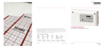
1
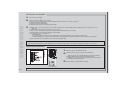
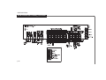
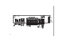
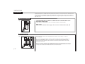
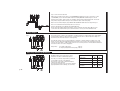
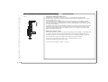
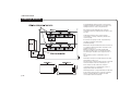
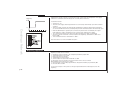
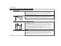
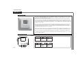
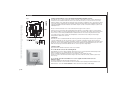
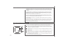
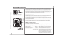
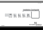
Limit Sensor - WLTD and WLCT
Waterlilne Room sensors
p. 45
Room sensors/controllers with a limit sensor have a mechanical jumper on the printed circuit board
allowing the limitation to be set for MIN. or MAX. temperature control. If set for MAX., it will have a
temperature setting of 27°C. Set for MIN., it has a setting of 17°C. These temperature are fixed when
used with masters WLM-1BA or WLM-3BA unless the Room sensor has been allocated to a zone
group controlled by a WLCT Room controller. In this case, the limit settings can be increased or
decreased by accessing the Room controller. The limits then set will apply to all relevant Room sensors
with limit sensors belonging to that group. If the master WLM-1FS or WLM-3FS is used, the limit
settings can be changed through the programming buttons on the master.
Mounting of limitation sensor
Jumper mounted: max. limitation
Jumper removed: min. limitation
Max. temperature limitation is used to protect the floor area from becoming too warm. This may be
required if special floor surfaces (real wood) are used. The sensor should be positioned where it can
read the true temperature of the floor and should always be within the heated area.
Min. temperature limitation is used to keep a floor surface warm, irrespective of room temperature.
For example, water on tiled bathrooms or pool areas with dry more quickly if the floor surface is kept
warm. The sensor should be positioned where it can read the true temperature of the floor and should
always be within the heated area.
For easy replacement we recommend that all floor sensors are mounted in a tube which is placed
between 2 heating pipes. The inner end of the tube should be sealed, and the sensor cable brought
back to the wall edge. If required, the sensor cable can be extended up to 50 m with a standard
installation cable.
WLTM: Use of external room sensor
A remote room sensor can be used instead of the built-in sensor by connecting the jumper across the
two pin bridge on the printed circuit board under the
Room sensor cover. From factory the jumper is “parked” on one pin. Location of jumper see fig. 3.
Technical Data (Wireless)
Supply Voltage Batteries, 2 x AAA Alkaline 1,5 V
Distance to master . . . . . . . . . . . . . . .Max 30 m
Enclosure . . . . . . . . . . . . . . . . . . . . . . . . . .IP 21
Ambient temperature range . . . . . . . . 0 to 40°C
Communication frequency . . . . . . . . . 868 MHz
Communication distance . . . Up to 30 m inside,
Up to 100 m outside
Batteries (Wireless)
The Room sensors use 2 x AAA batteries type
Alkaline. A lifetime of 1-2 years is expected. The
Room sensors are equipped with a low battery
alarm giving a little bip each 5 minutes in case
of low battery. If a Room sensor is defective or if
the communication to the unit is interrupted, an
alarm will be triggered on the master, and the room
will be heated at constantly 20% as safety. The
alarm can be overruled in the next 24 hours. On
the Room controller press the clock symbol for 2
sec. On the other Room sensors remove the front
cover and press the little learning mode button for
2 seconds.