1
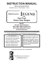
INSTRUCTION MANUAL
INSTALLATION AND SERVICE
Destination country: United Kingdom; Ireland
MONTAGUE
Gas Fired
Heavy Duty Ranges
Models:
E12, E18, E24 & E36 Series
EM12, EM18, EM24 & EM36 Series
EC12, EC18, EC24 & EC36 Series
E136 & E136R Series
It is required by law that all gas appliances are installed by competent persons in accordance with the
LOCAL GAS SAFETY REGULATIONS. Failure to install appliances correctly can lead to prosecution. It is
in your own interests and that of safety to insure that there is compliance with the law.
IF YOU SMELL GAS
1. TURN OFF THE APPLIANCE AT
THE GAS INLET COCK AND OPEN
ALL DOORS AND WINDOWS.
2. DO NOT OPERATE ANY ELECTRICAL SWITCHES AND EXTINGUISH ALL NAKED FLAMES.
3. CONTACT THE LOCAL GAS
AUTHORITY IMMEDIATELY.
THE FOLLOWING INSTRUCTIONS
SHOULD BE READ CAREFULLY AS
THE MANUFACTURER CANNOT BE
HELD RESPONSIBLE FOR ANY DAMAGE TO PROPERTY, PERSONS OR
ANIMALS CAUSED BY INCORRECT
INSTALLATION OR OPERATION OF
THE APPLIANCE.
PLEASE RETAIN THIS MANUAL FOR FUTURE REFERENCE.
THE MONTAGUE COMPANY
1830 STEARMAN AVENUE, P.O. BOX 4954
HAYWARD, CA 94540-4954
TEL: 510/785-882224FAX: 510/785-3342
IMPORTANT
WARNING:
Improper installation, adjustment,
alteration, service or maintenance
can cause property damage, injury
or death. Read the operating and
maintenance
instructions
thoroughly before installing or
servicing this equipment.
FOR YOUR SAFETY:
Do not store or use gasoline or
other flammable vapors and
liquids in the vicinity of this or
any other appliance.
SHIPPING DAMAGE CLAIM PROCEDURE
For your protection, please note that equipment in this shipment was carefully inspected and packed by
skilled personnel before leaving the factory. The transportation company assumed full responsibility for
safe delivery upon acceptance of this shipment.
If shipment arrives damaged:
1. VISIBLE LOSS OR DAMAGE - Be certain this is noted on freight bill or express receipt, and signed by
person making delivery.
2. FILE CLAIM FOR DAMAGES IMMEDIATLY - Regardless of the extent of damage.
3. CONCEALED LOSS OR DAMAGE - If damage is unnoticed until merchandise is unpacked, notify
transportation company or carrier immediately, and file "concealed damage" claim with them. This should
be done within fifteen (15) days of date that delivery was made to you. Be sure to retain container for
inspection.
We cannot assume responsibility for damage incurred in transit. We will, however, be glad to furnish you
with necessary documents to support your claim.
23
INSTALLATION
STATUTORY REGULATIONS
The installation of this appliance must be carried out by a competent person and in accordance
with the relevant regulations, standards, codes of practice and the related publications of the
country of destination.
TECHNICAL SPECIFICATIONS
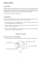
GAS SUPPLY
The gas pipe connection is made at the rear of the equipment, or into the end of the manifold
battery. The size of the pipe work supplying the appliance must not be less than the inlet
connection. An isolating cock is recommended to be close to the appliance to allow shut down
during an emergency or routine servicing. After installation, the complete pipe work must be
checked for soundness.
DATA PLATE LOCATION
The data plate is readily accessible, located behind the lower oven burner access door. It
contains all of the pertinent information required by the installer.
MODEL DESIGNATION
UNIT PREFIX:
E12 ......................
E18 ......................
E24 ......................
E36 ......................
EC12 ......................
EC18 ......................
EC24 ......................
EC36 ......................
EM12 ......................
EM18 ......................
EM24 ......................
EM36 ......................
E136 ......................
E136R......................
2/
......................
12" add-a-unit
18" add-a-unit
24" add-a-unit
36" add-a-unit
12" counter unit
18" counter unit
24" counter unit
36" counter unit
12" unit w/ modular stand
18" unit w/ modular stand
24" unit w/ modular stand
36" unit w/ modular stand
36" oven
36" oven w/ controls located on left side
identical appliances are connected
1
INSTALLATION
UNIT SUFFIX:
-0
.......... 24" Fry Top on left, 12" Hot Top on right
-0E .......... 24" Fry Top on left, 12" even heat Hot Top on right
-1
.......... 12" Fry Top on left, two 12" Hot Tops on right
-1E .......... 12" Fry Top on left, two 12" even heat Hot Tops on right
-2
.......... two 12" Open Tops on left, 12" Hot Top on right
-2E .......... two 12" Open Tops on left, 12" even heat Hot Top on right
-3
.......... two 12" Hot Tops on left, 12" Open Top on right
-3E .......... two 12" even heat Hot Tops on left, 12" Open Top on right
-4
.......... 12" Hot Top on left, two 12" Open Tops on right
-4E .......... 12" even heat Hot Top on left, two 12" Open Tops on right
-5
.......... 12" Open Top(s)
-5A .......... 18" Hot Top(s)
-6
.......... 12" Fry Top on left, two 12" Open Tops on right
-7
.......... 24" Fry Top on left, 12" Open Top on right
-8
.......... Fry Top
-9
.......... 12" Hot Top(s)
-9E .......... 12" even heat Hot Top(s)
-9A .......... 18" Hot Top(s) w/ ring and cover
-9ASE.......... 18" even heat Hot Top(s)
-10
.......... 12" Open Top on left, two 12" Hot Tops on right
-10E .......... 12" Open Top on left, two 12" even heat Hot Tops on right
-11
.......... 18" Hot Top w/ ring and cover on left, 18" Open Top on right
-11E .......... 18" even heat Hot Top on left, 18" Open Top on right
-12
.......... 18" Fry Top on left, 18" Hot Top w/ ring and cover on right
-12E .......... 18" Fry Top on left, 18" even heat Hot Top on right
-13
.......... 18" Fry Top on left, 18" Open Top on right
-14
.......... 18" Open Top on left, 18" Hot Top w/ ring and cover on right
-14E .......... 18" Open Top on left, 18" even heat Hot Top on right
-15
.......... 18" even heat Hot Top on left, 18" Hot Top w/ ring and cover on right
-16
.......... 18" Hot Top w/ ring and cover on left, 18" even heat Hot Top on right
-40
.......... 42" range depth
{-0R, -0ER, -1R, -1ER, -6R,
-7R, -12R, -12ER, or -13R} ................................. Fry Top on right side
{-0GG, -0EGG, -1GG, -1EGG, -6GG,
-7GG, -8GG, -12GG, -12EGG, or -13GG} ........ Grooved Griddle Fry Top
2
INSTALLATION
GENERAL INFORMATION
1. Check carton or crate for possible damage sustained during transit. Carefully remove unit
from carton or crate and again check for damage. Any damage to the appliance must be
reported to the carrier immediately.
2. The wires or ties for retaining the burners and other packing material must be removed
from units. Any protective material covering stainless steel parts must also be removed.
3. All equipment is shipped from the factory without the legs fitted, unless otherwise specified.
4. The high shelf is packed separately.
5. The type of gas and supply pressure that the equipment was set up for at the factory is
noted on the data plate and on the packaging. This type of gas supply must be used.
6. Do not remove permanently affixed labels, warnings or data plates from the appliance, for
this may invalidate the manufacturer's warranty.
TABLE A: HEAT INPUT (GROSS) PER BURNER
2nd FAMILY, GROUP H
3rd FAMILY, GROUP 3P
(G20 @ 20 mbar) NATURAL GAS
(G31 @ 37 mbar) PROPANE
Per burner / section
Per burner / section
MODELS /
SECTION
kW
BTU/HR
kW
BTU/HR
E136 OVEN
11.72
40,000
11.72
40,000
OPEN TOP
5.86
20,000
5.83
20,000
12" HOT TOP
5.42
18,500
5.42
18,500
5.86
20,000
5.86
20,000
FRY TOP
4.4
15,000
4.4
15,000
18" HOT TOP
10.26
35,000
10.26
35,000
18" EVEN HEAT
HOT TOP
2 burners
@ 5.86
2 burners
@ 20,000
2 burners
@ 5.86
2 burners
@ 20,000
12" EVEN HEAT
3
INSTALLATION
TABLE B: SETTING PRESSURE/INJECTOR SIZE
2nd FAMILY, GROUP H
3rd FAMILY, GROUP 3P
Setting
Pressure
Setting Pressure
MODELS /
SECTION
Injector
Siz e
Injector
Siz e
G31 @ 37
mbar
G20 @ 20 mbar
mbar
i.w.c.
I.D. #
mm
mbar
i.w.c.
I.D. #
mm
E136 OVEN
15
6.0
31
3.05
25
10.0
48
1.93
OPEN TOP
15
6.0
49
1.85
25
10.0
55
1.32
12" HOT TOP
15
6.0
50
1.78
25
10.0
56
1.18
12" EVEN HEAT
HOT TOP
15
6.0
49
1.85
25
10.0
55
1.32
FRY TOP
15
6.0
52
1.61
25
10.0
57
1.09
18" HOT TOP
15
6.0
37
2.64
25
10.0
49
1.85
18" EVEN HEAT
HOT TOP
15
6.0
49
1.85
25
10.0
55
1.32
NOTE:
The pressure must be measured at the pressure test nipple located on the main manifold
pipe with all burners lit.
TABLE C:
AERATION SHUTTER SETTING / PILOT FLAME SETTING
2nd FAMILY, GR OU P H
MOD EL/SEC TION
(G20 @ 20 mbar)
N ATU R AL GAS
3rd FAMILY,
GR OU P 3P
(G31 @ 37 mbar)
PR OPAN E
PILOT FLAME
LEN GTH
mm
ins.
mm
ins.
mm
ins.
E136 Oven
22.5
0.89
25.4
1.00
12.7
0.50
Open Top
17.8
0.7
19.0
0.75
12.7
0.50
Fry Top
15.2
0.6
16.5
0.65
12.7
0.50
12", 18" H ot Top
12.7, 19.0
0.5, 0.75
15.2, 20.3
0.6, 0.8
12.7
0.50
Even H eat H ot Top
15.2
0.6
16.5
0.65
12.7
0.5
NOTE:
Settings subject to 1/4 inch (6.35 mm) adjustment.
4
INSTALLATION
GENERAL INSTALLATION
SITING
The floor on which the range is to be sited must be capable of adequately supporting the
weight of the appliance and any ancillary equipment. Once in position check that the unit is
level, both front to back and side to side. Adjust if necessary using the adjusting foot on each
leg.
VENTILATION AIR
The following notes are intended to give general guidance. For detailed recommendations,
refer to the applicable code(s) in the country of destination.
Note 1:
The room containing the appliance is required to have a permanent air vent.
The minimum effective area of the vent is related to the maximum rated heat
input of the appliance and shall be 4.5 cm per kW in excess of 7 kW.
2
Note 2:
Air vents should be of such a size to compensate for the effects of any extract
fan in the premises.
GAS SUPPLY
The local gas region should be consulted at the installation planning stage in order to establish
the availability of an adequate supply of gas and to ensure that the meter is adequate for the
required flow rate. The pipe work from the meter to the appliances must be of an appropriate
size. Where a number of appliances are installed in a battery, no more than five should be
served by any one supply pipe.
All fixed (non-mobile) appliances MUST be fitted with a manual gas cock upstream of the
appliance to provide a means of isolation for servicing or cleaning purposes. A union or
similar means of disconnection must be provided between the gas cock and the appliance.
A manually operable valve must be fitted to the gas supply to the kitchen to enable it to be
isolated in an emergency. Wherever practical, this shall be located either outside the kitchen
or near to an exit in a readily accessible position.
Where it is not practical to do this, an automatic isolation valve system shall be fitted which
can be operated from a readily accessible position near to the exit.
At locations where the manual isolation valve is fitted or the automatic system can be reset a
notice MUST be fitted stating:
"ALL DOWNSTREAM BURNER AND PILOT VALVES MUST BE TURNED OFF PRIOR TO
ATTEMPTING TO RESTORE THE SUPPLY. AFTER EXTENDED SHUT OFF, PURGE
BEFORE RESTORING GAS."
5
INSTALLATION
CLEARANCES
The space in which the range is to be sited must include the minimum installation clearances
to combustible surfaces shown in Table D:
TABLE D: MINIMUM INSTALLATION CLEARANCES TO COMBUSTIBLE CONSTRUCTION
TOP
LEFT SIDE
RIGHT SIDE
REAR
MODELS
All
mm
ins.
mm
ins.
mm
ins.
mm
ins.
914
36
152
6
152
6
51
2
TYPE of FLOOR
or BASE
Combustible*
*Counter Models for installation on noncombustible counters only.
Models without legs for installation on noncombustible floors.
o
Caution : High surface temperatures (80-125 C) are sometimes generated on the left side of the unit.
(Or the right side with a reversed thermostat.) The user may wish to employ a protective shield
when the appliance is not banked or put against a non combustible wall.
INSTALLATION PROCEDURE
Carefully remove range from crate. Burner tie wires and other packing material must be
removed from the unit. On stainless steel units, the protective material covering the stainless
steel must be removed immediately after unit is installed. Do not lift range by the front guard
rail. If range is equipped with a frytop section, remove wood shipping strips located below
grease trough.
ASSEMBLY
Uncrate range as near to final location as possible. Remove all shipping wire from burners
and all packing material and accessories from oven interior. Then assemble as follows:
1. Screw the adjustable feet of the legs in all the way. Then tightly screw the complete leg
assembly into the mounting holes at each corner of the range. If the unit is intended for curb
installation, no legs are provided. The curb must be noncombustible material
2. Install door handle and secure with screws that are provided. Observe "UP" marking on
handle for correct orientation.
3. If top castings are removed, identify castings so they are replaced in the same position on
same range as when received from the factory.
SETTING IN PLACE
BATTERY ARRANGEMENT
Floor Mounted Ranges:
1. Place the first range in the exact position it will occupy in the battery.
6
INSTALLATION
2. Using a carpenter's level, level range from front to rear and side to side. Adjust as follows:
FLOOR INSTALLATION ON LEGS: Adjust by turning foot on adjustable leg.
CURB INSTALLATION: Place shim under the low side. This operation is important since
variation in floor and curbs are common. Unless ranges are level, difficulty will be encountered
in aligning the gas supply manifold and the ranges will not butt together tightly.
3. Remove the upper valve panel from range.
4. Move the next range into position.
5. Engage union nut on manifold with male fitting on next range and draw up union nut hand
tight. Be sure appliances butt together both front and rear. If manifolds do not align, then
ranges are not level. In extreme cases, it may be necessary to loosedn manifold bolts and
adjust.
6. Continue leveling and connecting gas supply manifolds together until all appliances in
battery are connected.
7. Tighten manifold union gas tight. Use back up wrench to prevent manifold from rotating.
FAILURE TO DO THIS MAY RESULT IN DAMAGE TO PILOTS AND GAS VALVES.
MODULAR RANGES:
Assemble modular base and set in place. Adjust feet as explained above. Connect ranges as
shown for battery arrangement.
FRY TOP RANGES:
Fry Top Plate Adjustment: Leveling bolts are at the rear of the range under the fry top
plate. Adjust leveling bolts so that the plate is pitched to the front to provide for grease runoff.
HIGH SHELVES AND SALAMANDER BROILERS:
Lift high shelf or broiler above the range and slide legs into position.
This range is designed for use with a gas pressure governor.
The governor supplied with this unit must be used.
7
INSTALLATION
LEGS/CASTERS
Where the range is to be fitted with casters, it must be connected to the installation pipe by a
corrugated metallic flexible connection and incorporating a self-sealing plug & socket. At
least two casters must be fitted to the front of the range and must be fitted with a brake or
locking device. Non swivelling casters must be fitted to the rear of the range.
Do not install the range without legs or casters.
COMMISSIONING
The whole of the gas installation, including the meter, should be inspected, purged and tested
for soundness in accordance with the codes of the country of destination.
1. Ensure that all gas taps are in the "O" position and turn on the main gas supply. Light all
pilots in accordance with the User's Instructions.
2. Connect a U-gauge manometer to the pressure test point on the main manifold. Turn all
gas taps to the full on " " position.
3. Check that the setting pressure is correct per Table B on page 3. If necessary, adjust the
pressure governor to give the required setting.
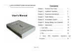
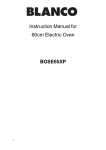
BURNER ADJUSTMENTS
OPEN TOP / HOT TOP / FRY TOP BURNER
1. Check that the aeration shutter is set to provide the required opening per Table C (See Figure 1).
AERATION SHUTTER
FIXING SCREW
LENGTH OF OPENING
INJECTOR LOCATION
FIG. 1
8
INSTALLATION
PILOT ADJUSTMENT - TOP BURNERS
OPEN TOP, HOT TOP & FRY TOP: The pilots are controlled by fixed injectors and cannot
be adjusted.
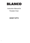
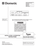
OVEN MINIMUM FLAME SETTING
This is the flame that must be maintained on the burner when the oven has come up to the
temperature set on the dial. Enough gas must be bypassed by the control to keep the entire
burner lit. The thermostat regulates the flame from high to low in accordance with the oven
temperature and will automatically turn down to this minimum flame when the temperature
set on the dial is attained in the oven.
BY-PASS FLAME
ADJUSTOR
DIAL
STOP
SCREW
CLEARANCE
SLOTS
CALIBRATION
PLATE
CALIBRATION
LOCK SCREWS
P/N 01061-8
o
1. Light the oven, set thermostat to 100 C and allow 5 minutes for the oven temperature to
stabilize.
2. After oven temperature rises and remains constant turn dial back to low. This closes main
valve and permits only the bypass gas to the burner.
9
INSTALLATION
4. Remove dial.
5. With a screwdriver, turn the bypass flame adjustor screw counterclockwise to increase the
bypass flame or clockwise to decrease it until the flame over the entire burner is approximately
4 mm high. Replace dial.
THERMOSTAT CALIBRATION CHECK
The calibration of this thermostat should not be changed until considerable experience with
cooking results has definitely proved that the thermostat is not maintaining the proper
temperature. The re-calibration should not be made until the bypass (minimum burner) flame
has been properly adjusted.
If re-calibration becomes necessary, the following procedure should be followed:
1. Place the thermocouple of test instrument or thermometer in the middle of the oven.
2. Light the main burner.
3. Turn dial to between the "180" and the "200" position (190).
4. Allow the oven to heat until the flame cuts down to bypass. After sufficient time, check
tmeperature. If the temperature does not read within 10 degrees of the dial setting, recalibrate
as follows:
a. Pull dial straight off without turning.
b. Hold calibration plate and loosen the two calibration lock screws until the plate can be
moved independently of the control.
c. Turn calibration plate so that the instrument or thermometer reading is in line with the indicator
mark. Hold plate and tighten screws firmly. Turn the calibration plate counterclockwise if the
test reading is higher than the dial setting, or clockwise if the reading is lower than the dial
setting. Replace dial.
NOTE: If the above adjustment is prevented by the two loosened calibration lock scews being
in ontact with the ends of the screw clearance slots in the calibration plate, remove the screws
and after turning the calibration plate to the proper location, reassemble screws in the other
tapped holes designed for them.
OVEN
A. Light pilot in accordance with the User's Instructions.
B. Check that the length of the pilot flame is correct per Table C.
All pilot flames should envelope the tip of the thermocouple. The pilot flame can be viewed
through the opening in front of the burner compartment panel.
Replace the burner access panel.
Hand the User's Instructions to the user or purchaser for retention and instruct them in the
efficient and safe operation of the appliance.
Tell the user of the location of the gas isolation cock for use in an emergency.
Leave this Installation and Service Instruction Manual with the user or purchaser.
10
MAINTENANCE
MAINTENANCE AND SERVICING INSTRUCTIONS
Regular maintenance by a competent person is recommended to ensure the continued safe
and efficient performance of the appliance.
Should service be required, kindly contact your dealer for assistance. Alternatively, please
contact us at the following address:
THE MONTAGUE COMPANY
1830 STEARMAN AVENUE
HAYWARD, CALIFORNIA 94545
Telephone: (510) 785-8822
Fax: (510) 785-3342
WARNING: Turn off the gas supply to the appliance at the service cock before
commencing any servicing work.
IMPORTANT: Test for gas soundness on completion of any servicing work.
GAS TAPS
Re-greasing of the taps is not recommended. If the tap spindles become seized or difficult to
turn, refer to the Replacement of Parts section in this manual.
CLEANING BURNERS
OPEN TYPE HOT PLATE
1. Lift off the pan supports.
2. Lift the front burner to disengage the locating nipple and slide backwards off the injector.
3. Remove the rear burner in the same manner.
4. Clean the burners in hot soapy water with a stiff scrubbing brush.
5. Rinse and shake well to remove any water.
6. Ensure that the ports are clear of any debris.
7. Reassemble in the reverse order.
11
MAINTENANCE
GRIDDLE / SOLID HOT PLATE
1. Lift off the griddle plate or solid top. (Use caution. This will require assistance due to
the weight of the griddle/plate).
2. Lift rear of burner and slide backwards off the injector.
3. Clean the burners in hot soapy water with a stiff scrubbing brush.
4. Rinse and shake well to remove any debris.
5. Reassemble in the reverse order.
OVEN
1. Remove the oven bottom.
2. Remove the flame spreader and heat deflector above the burner by lifting out.
3. Lift rear of burner and slide backwards off the injector.
4. Clean the burner with a stiff scrubbing brush and shake well to ensure that the ports
are clear of any debris.
5. Reassemble in the reverse order.
PILOT BURNER CLEANING
1. Disconnect the pilot gas supply tubing from the pilot.
2. Remove the pilot injector.
3. Clean by blowing through or washing. Do not use wire to clear the pilot injector.
4. Reassemble in the reverse order.
12
MAINTENANCE
MISCELLANEOUS
1. Wire brush the surface of the griddle to remove baked on material, wash with hot water,
dry thoroughly and reassemble. Lightly coat the surfaces with vegetable oil to prevent
rusting.
2. Grease the door hinges and check for loose fasteners. Tighten as necessary.
3. Clean out all grease drawers and wash with hot soapy water. Dry thoroughly.
4. Wipe exposed cleanable surfaces with a mild detergent and hot water. Stubborn
residue may be removed with a lightweight non-metallic scouring pad. Stainless
steel areas should be washed with a mild detergent, hot water and a soft cloth. If
necessary to use a non-metallic scouring pad always rub in the direction of the grain
in the metal to prevent scratching. NEVER USE STEEL WOOL.
5. Check the operation of all thermocouples and flame safety devices by lighting the pilots
individually and then blowing them out. Listen for the flame failure valve clicking closed.
This action must occur within 60 seconds of extinguishing the pilot.
6. Clean oven racks, shelves and guides with hot soapy water and dry thoroughly. Clean
the oven interior with a propriety oven cleaner following the manufacturers instructions.
REPLACEMENT OF PARTS
WARNING: Disconnect the gas supply to the appliance at the service cock and the
power supply at the mains before commencing any servicing work.
IMPORTANT: Test for gas soundness on completion of any servicing work.
GAS TAPS
1. Pull the knob off each gas tap below the guard rail on the range.
2. Remove the screws securing the fascia panel and remove panel.
3. Remove the appropriate burner (if necessary) following the prodecure given under the
section on main burner cleaning.
4. Disconnect the thermocouple connection at the gas tap.
5. Disconnect the pilot tubing connection at the gas tap.
6. Remove the two screws from the top of gas tap and remove the tap.
7. Replace with the new tap.
8. Reassemble in the reverse order.
13
MAINTENANCE
THERMOSTAT
1. Pull the knob off the thermostat on the range.
2. Remove the bottom and topscrews securing the vertical fascia panel and remove panel.
3. Disconnect the tubing between the oven gas tap and thermostat.
4. Disconnect the tubing between the thermostat and the oven burner injector.
5. Release the oven sensor retaining clips from the oven lining and the sensor from the clips.
6. Withdraw the sensor from the oven compartment.
7. Seperate the thermostat from the mounting flange removing the two fixing screws.
8. Fit the replacement thermostat by reassembling in the reverse order.
PILOT BURNER / THERMOCOUPLE / SPARK ELECTRODE
OPEN TYPE HOT PLATE / SOLID HOT PLATE / GRIDDLE / OVEN
1. Remove the burners following the procedure given under Burner Cleaning.
2. Remove the screws securing the fascia panel and remove the panel.
3. Disconnect the thermocouple connection at the gas tap.
4. Disconnect the pilot tube connection at the gas tap.
5. Remove the two (2) screws that secure the pilot burner and remove pilot burner,
thermocouple or spark electrode as appropriate.
6. Replace the faulty component and reassemble in the reverse order.
NOTE:
The connection between the thermocouple and the flame safety device must not
be over-tightened. It is sufficient for it to be finger-tight plus a quarter of a turn.
PIEZO IGNITOR
1. Remove the control knobs from all the gas taps and thermostats.
2. Remove the screws securing the front fascia panel and remove the panel.
3. Remove the defective piezo ignitor and replace.
4. Reassemble in the reverse order.
14
MAINTENANCE
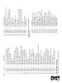
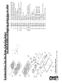
RENEWAL PARTS
WARNING: Disconnect the gas supply to the appliance at the service cock at the main
before commencing any servicing work.
IMPORTANT: Test for gas soundness on completion of any servicing work.
15
16
1830 Stearman Avenue, Hayward, California 94545
The Montague Company
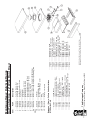
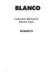
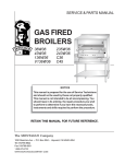
Montague E136 Series
Heavy Duty Range Parts List
17
Part # .........
Description
1830 Stearman Avenue, Hayward, California 94545
The Montague Company
1 ......... 8955-9 ............... Door Panel , Ext . - ptd (with nameplate)
1 ......... 7644-9 ............... Door Panel, Ext. - S/S (with nameplate)
1 ......... 6134-4 ............... Door Panel, Ext. - ptd (with embossed “M”)
1 ......... 6135-2 ............... Door Panel, Ext. - S/S (with embossed “M”)
2 ......... 1548-2 ............... Door Panel, Int., (prior 8/84)
2 ......... 2428-7 ............... Door Panel, Int., (post 8/84)
3 ......... 1424-9 ............... Insulation, Door
4 ......... 3173-9 ............... Handle, Door
5 ......... 2004-4 ............... Handle, Main Oven Valve
6 ......... 3566-1 ............... Valve Panel - 36", S/S (specify width)
6 ......... 4576-4 ............... Valve Panel - 34", S/S (frytop models only)
7 ......... 1056-1 ............... Valve, Oven - 1/4" NPTM x 7/16"cc (new style)
7 ......... 4490-3 ............... Valve, Oven - 9/16"-27 x 7/16"cc (old style)
8 ......... 1288-2 ............... Pilot Fitting - 1/8" NPT x 1/4" tube
9 ......... 6137-9 ............... Bracket, Valve Panel
10 ....... 1073-1 ............... Manifold - 36", Comb. (order by length & model)
11 ....... 6860-8 ............... Guard Rail - 36", S/S (post 1/85-consult factory)
12 ....... 4285-4 ............... Manifold Drip Shield (specify length)
13 ....... 1547-4 ............... Oven Bottom - Porcelain (change #17)
13 ....... 9051-4 ............... Oven Bottom - Porcelain (change #18)
13A .... 4387-7 ............... Oven Bottom - Cast Iron (sold as pair)
13A1 .. 7987-1 ............... Heat Deflector for 13A Bottom
14 ....... 4601-9 ............... Heat Deflector
15 ....... 6593-5 ............... Burner Baffle, S/S
16 ....... 9044-1 ............... Side Liner, Oven - Right (change #18)
17 ....... 9043-3 ............... Side Liner, Oven - Left (change #18)
18 ....... 1538-5 ............... Top Liner, Oven - Porcelain
19 ....... 12874-0 ............. Interior Liner - Left & Right (with stiffener)
20 ....... 12894-5 ............. Insulation, Oven - Left, Right & Rear
21 ....... 7223-0 ............... Rack Guide - Left or Right
22 ....... 1942-9 ............... Clip, Thermostat Bulb
23 ....... 1536-9 ............... Rear Liner, Oven - Porcelain
24 ....... 6149-2 ............... Bracket, Orifice Fitting - Oven
25 ....... 1013-8 ............... Thermocouple Please Order By Part# and Description
26 ....... 2190-3 ............... Orifice, Oven Pilot (Nat. Gas)
26 ....... 2191-1 ............... Orifice, Oven Pilot (LP Gas)
27 ....... 6155-7 ............... Compression Nut & Ferrel - 1/4" tube
28 ....... 1017-0 ............... Pilot Burner (Nat. Gas)
28 ....... 1018-9 ............... Pilot Burner (LP Gas)
29 ....... 6150-6 ............... Orifice, Main Burner (Nat. Gas)
29 ....... 6151-4 ............... Orifice, Main Burner (LP Gas)
30 ....... 3604-8 ............... Tubing - 1/4" (safety valve to pilot burner)
31 ....... 3602-1 ............... Tubing - 7/16" (thermostat to burner-42")
32 ....... 6152-2 ............... Elbow Assembly w/Orifice (Nat. Gas)
32 ....... 6153-0 ............... Elbow Assembly w/Orifice (LP Gas)
33 ....... 2037-0 ............... Air Mixer, Oven Burner
34 ....... 6350-9 ............... Burner, Oven (new style less pilot mount)
35 ....... 9518-4 ............... Baffle, Main Oven Burner
36 ....... 1062-6 ............... Safety Valve, Pilot
37 ....... 1277-7 ............... Fitting - 1/4" tube (tapered, compression)
38 ....... 1061-8 ............... Thermostat, FDTO (with dial 500)
Item .........
........... 01061-8 ............. THERMOSTAT
........... 26621-3 ............. FLAME FAILURE VALVE (w/ elbow)
........... 26622-1 ............. FLAME FAILURE VALVE (w/o elbow)
........... 26168-8 ............. OVEN PILOT BURNER
........... 26169-6 ............. INJECTOR - G20 NATURAL GAS
........... 26171-8 ............. INJECTOR - G31 LP GAS
........... 26177-7 ............. THERMOCOUPLE - M9X1 1500 MM
........... 26178-5 ............. ADAPTER - M8/M9
........... 26172-6 ............. SLEEVE, COMPRESSION - 1/4" TUBE
........... 26173-4 ............. NUT, COMPRESSION - 1/4" TUBE
........... 26174-2 ............. ELECTRODE- OVEN, HOT TOP, FRY TOP
........... 25716-8 ............. PIEZO IGNITOR W/ NUT
........... 26176-9 ............. IGNITOR WIRE - OVEN
........... 27986-2 ............. IGNITOR WIRE - FRY/ HOT TOP
........... 26179-3 ............. PILOT BURNER - TOP SECTIONS
........... 26180-7 ............. INJECTOR - G20 NATURAL GAS
........... 26181-5 ............. INJECTOR - G31 LP GAS
........... 26186-6 ............. THERMOCOUPLE - M8X1 600 MM
........... 26183-1 ............. SLEEVE, COMPRESSION - 3/16" TUBE
........... 26185-8 ............. NUT, COMPRESSION - 3/16" TUBE
........... 03361-8 ............. BURNER, FRY TOP - "A"
........... 03353-7 ............. BURNER, 12" HOT TOP - "B"
........... 03356-1 ............. BURNER, 18" HOT TOP - "C"
........... 03346-4 ............. BURNER, OPEN TOP - "D"
........... 06530-9 ............. BURNER, E136 OVEN- "E"
........... 03362-6 ............. BURNER, EVEN HEAT - "F"
........... 27106-3 ............. THERMOSTAT DIAL
European / Flame - Failure Valve Variations
E136 Series Only
39 ....... 1977-1 ............... Dial, FDTO Thermostat
40 ....... 1287-4 ............... Fitting 3/8" NPT x 7/16" tube
41 ....... 3600-5 ............... Tubing 7/16" (main valve to safety—change #8)
42 ....... 1150-9 ............... Nipple, Pipe - 3/8" x 2"
43 ....... 3605-6 ............... Tubing 1/4" (manifold to safety valve)
44 ....... 3459-2 ............... Panel, Firebox - Ptd (change #14-clip style)
44 ....... 3524-6 ............... Panel, Firebox - S/S (change #14-clip style)
45 ....... 1260-2 ............... Spacer, Door Pin
46 ....... 6077-1 ............... Door Trunnion - Right
47 ....... 6979-8 ............... Door Trunnion - Left
48 ....... 3393-6 ............... Pin, Oven Door
49 ....... 4274-9 ............... Door, Pilot Access
50 ....... 4275-7 ............... Burner Compartment Front
51L ..... 6346-0 ............... Baffle, Air - Left
51R .... 6348-7 ............... Baffle, Air - Right
52 ....... 4645-0 ............... Panel, Right Front Control - Ptd (after 9/70)
52 ....... 4610-8 ............... Panel, Right Front Control - S/S (after 9/70)
53 ....... 4288-9 ............... Panel, Left Front Control - Ptd (after 9/70)
53 ....... 4286-2 ............... Panel, Left Front Control - S/S (after 9/70)
54 ....... 3468-1 ............... Leg - 6" Ptd
54 ....... 3467-3 ............... Leg - 6" S/S
55 ....... 9005-0 ............... Rack, Oven - 25-5/8" x 26"
56 ....... 6926-4 ............... Catch, Spring (female)
57 ....... 7584-1 ............... Support, Channel
1830 Stearman Avenue, Hayward, California 94545
The Montague Company
Part #
1 ....... 04330-3 .........
1 ....... 01003-0 .........
1 ....... 02101-1 .........
1 ....... 01002-2 .........
3 ....... 02002-8 .........
4 ....... 03348-0 .........
4. 6, 7, 8 .. 03347-2 .........
5 ....... 03350-2 .........
5, 6, 7, 8 .. 03349-9 .........
5A, 6, 7, 8 03351-0 .........
6 ....... 02115-6 .........
7 ....... 03346-4 .........
8 ....... 02038-9 .........
9 ....... 01055-3 .........
10 ..... 03583-1 .........
10, 11, 20 03431-2 .........
10, 12, 20 03430-4 .........
20, 21, 22 07142-0 .........
13 ..... 01518-0 .........
14 ..... 03379-0 .........
14 ..... 03378-2 .........
14 ..... 03377-4 .........
15 ..... 03380-4 .........
16 ..... 03498-3 .........
16 ..... 03530-0 .........
16 ..... 03531-9 .........
16 ..... 03532-7 .........
17 ..... 03480-0 .........
18 ..... 03580-7 .........
19 ..... 03482-7 .........
22 ..... 06232-4 .........
23 ..... 03556-4 .........
Item
Valve, Top Burner (Nat) Except 1/2 Hot Top
Valve, Top Burner (LP) Except 1/2 Hot Top
Valve, Top Burner (Nat) 1/2 Hot Top Only
Valve, Top Burner (LP) 1/2 Hot Top Only
Handle, Valve w/Set Screw
Venturi, Front Burner
Burner, Front - Complete
Venturi, Rear Burner (Left swing shown)
Burner, Rear Left - Complete
Burner, Rear Right Complete (not shown)
Gasket
Burner Head Only
Air Mixer
Pilot Valve
Lighter, Pilot
Pilot Kit - 12" Section (Less Valve)
Pilot Kit - 18" Section (Less Valve)
Pilot Kit - 12" -59 Section (Less Valve)
Pilot Bracket
Drip Tray - 36" Unit
Drip Tray - 24" Unit
Drip Tray - 18" & 12" Unit
Drip Tray Guide
Support, Open Burner 36" Unit
Support, Open Burner 24" Unit
Support, Open Burner 18" Unit
Support, Open Burner 12" Unit
18" Open Top
12" Open Top
12" Combination -59 Top (1/2 Hot Top)
Lighter, Pilot
Bracket, Pilot MTG (-59 Top)
Description
Montague Heavy Duty Gas Range - Open Top Section
12" and 18" Wide - 1/2 Open Top 1/2 Hot Top - 12" Wide
18
19
1830 Stearman Avenue, Hayward, California 94545
The Montague Company
Part #
Valve, Top Burner - Nat
Valve, Top Burner - LP
Handle, Valve W/Set Screws
Valve, Pilot
Pilot Lighter
Burner Support W/Insulation - 36"
Burner Support W/Insulation - 24"
Burner Support W/Insulation - 12"
Insulation Pad
Burner, 12" Hot Top
Air Mixer
Baffle, Burners - Cast Iron
Manifold Shield W/Stops
Insulated Side Shield
Hot Top - 12" Section
Description
Part #
1 ....... 04330-3 .........
1 ....... 01003-0 .........
3 ....... 02002-8 .........
4 ....... 01055-3 .........
5 ....... 03416-9 .........
6 ....... 03362-6 .........
7 ....... 02037-0 .........
8 ....... 10628-3 .........
8 ....... 04468-7 .........
8 ....... 10629-1 .........
8 ....... 07133-1 .........
9 ....... 03560-2 .........
10 ..... 03533-5 .........
10 ..... 03538-6 .........
11 ..... 01738-8 .........
12 ..... 01741-8 .........
Item
Valve, Top Burner Nat
Valve, Top Burner LP
Handle, Valve w/Set Screw
Valve, Pilot
Pilot Lighter
Burner, Even Heat Hot Top - Complete
Air Mixer
Support, Burner 36"
Support, Burner 24"
Support, Burner 18"
Support, Burner 12"
Baffle - Heat assy.
Baffle - Air Assy. 3-1/8" Wide
Baffle - Air Assy. 9-1/4" Wide
Hot Top, 12" Section
Hot Top, 18" Section
Description
Montague Heavy Duty Gas Range
Hot Top Section - Even Heat
12" and 18" Wide Front Fired
1 ....... 02406-6 .........
1 ....... 01003-0 .........
3 ....... 02002-8 .........
4 ....... 01055-3 .........
5 ....... 03421-5 .........
6 ....... 04299-4 .........
6 ....... 04284-6 .........
6 ....... 04283-8 .........
7 ....... ———— .........
9 ....... 03353-7 .........
10 ..... 02038-9 .........
11 ..... 01635-7 .........
12 ..... ———— .........
13 ..... 03560-2 .........
14 ..... 01738-8 .........
Item
Montague Heavy Duty Gas Range
Hot Top Section - 12" Wide Front Fired
20
Part #
Air Mixer
Insulated Side Shield
Hot Top - 18" W/Ring & Cover
Ring
Cover
Hot Top - 18" - Solid
1830 Stearman Avenue, Hayward, California 94545
The Montague Company
........... 01061-8 ............. THERMOSTAT
........... 26621-3 ............. FLAME FAILURE VALVE (w/ elbow)
........... 26622-1 ............. FLAME FAILURE VALVE (w/o elbow)
........... 26168-8 ............. OVEN PILOT BURNER
........... 26169-6 ............. INJECTOR - G20 NATURAL GAS
........... 26171-8 ............. INJECTOR - G31 LP GAS
........... 26177-7 ............. THERMOCOUPLE - M9X1 1500 MM
........... 26178-5 ............. ADAPTER - M8/M9
........... 26172-6 ............. SLEEVE, COMPRESSION - 1/4" TUBE
........... 26173-4 ............. NUT, COMPRESSION - 1/4" TUBE
........... 26174-2 ............. ELECTRODE- OVEN, HOT TOP, FRY TOP
........... 25716-8 ............. PIEZO IGNITOR W/ NUT
(2) [12/96 thru 2/00] - Integral Thermostat Safety Valve
(3) [3/00 thru present] - Separate Thermostat and Safety Valve
........... 26176-9 ............. IGNITOR WIRE - OVEN
........... 27986-2 ............. IGNITOR WIRE - FRY/ HOT TOP
........... 26179-3 ............. PILOT BURNER - TOP SECTIONS
........... 26180-7 ............. INJECTOR - G20 NATURAL GAS
........... 26181-5 ............. INJECTOR - G31 LP GAS
........... 26186-6 ............. THERMOCOUPLE - M8X1 600 MM
........... 26183-1 ............. SLEEVE, COMPRESSION - 3/16" TUBE
........... 26185-8 ............. NUT, COMPRESSION - 3/16" TUBE
........... 03361-8 ............. BURNER, FRY TOP - "A"
........... 03353-7 ............. BURNER, 12" HOT TOP - "B"
........... 03356-1 ............. BURNER, 18" HOT TOP - "C"
........... 03346-4 ............. BURNER, OPEN TOP - "D"
........... 06530-9 ............. BURNER, E136 OVEN- "E"
........... 03362-6 ............. BURNER, EVEN HEAT - "F"
........... 27106-3 ............. THERMOSTAT DIAL
Valve, Top Burner - Nat.
Valve, Top Burner - LP
Handle, Valve w/Set Screw
Valve, Pilot
Pilot Lighter
Baffle-Air Assy - 36" Unit
Baffle-Air Assy - 18" Unit
Burner & Brick Support - 36" Unit
Burner & Brick Support - 18" Unit
Brick (1-1/4 x 8 x 13)
Burner, 18" Hot Top - Complete (Right Swing)
Burner, 18" Hot Top - Complete (Left Swing) Not
Description
European / Flame - Failure Valve Variations
E136 Series Only
1 ....... 02408-2 .........
1 ....... 02405-8 .........
3 ....... 02002-8 .........
4 ....... 01055-3 .........
5 ....... 03419-3 .........
6 ....... 04412-1 .........
6 ....... 04414-8 .........
7 ....... 04281-1 .........
7 ....... 04298-6 .........
8 ....... 01764-7 .........
9 ....... 03356-1 .........
9A .... 03355-3 .........
Shown
10 ..... 02037-0 .........
11 ..... 03560-2 .........
12 ..... 01743-4 .........
13 ..... 01745-0 .........
14 ..... 01747-7 .........
15 ..... 01741-8 .........
Item
Montague Heavy Duty Gas Range
Hot Top Section - 12" Wide Front Fired
WARNING
If not installed, operated and maintained in
accordance with the manufacturer's instructions,
this product could expose you to substances in
fuel or in fuel combustion which can cause death
or serious illness and which are known to cause
cancer, birth defects or other reproductive harm.
ALL PERSONNEL IN THE WORKPLACE WHO MAY BE SUBJECT TO ANY EXPOSURE OF CARBON
MONOXIDE MUST BE WARNED OF SUCH POSSIBLE EXPOSURE. THIS WARNING SHOULD BE
CONVEYED IN A MANNER SO THAT IT IS CLEARLY UNDERSTOOD BY THE EMPLOYEE, AND
THE EMPLOYEE SHOULD BE ASKED IF IN FACT HE OR SHE UNDERSTANDS THE CORRECT
METHOD OF OPERATION OF THE EQUIPMENT AND THAT A RISK OF EXPOSURE EXISTS IF THE
EQUIPMENT IS OPERATED IMPROPERLY.
THE MONTAGUE COMPANY
1830 Stearman Avenue, P.O. Box 4954, Hayward, CA 94540-4954
Continuous product improvement is The Montague Company Policy, therefore specifications and design are subject to change without notice.
21
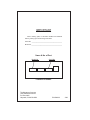
IMPORTANT
When ordering parts, to eliminate mistakes and facilitate
delivery, always give the following information:
Serial No. _________________________________________
Model No._________________________________________
Name & No. of Part
Model No.
Serial No.
LEGEND E136 SERIES
The Montague Company
1830 Stearman Avenue
P.O. Box 4954
Hayward, CA 94540-4954
P/N 28482-3
22
3/99