1
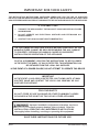
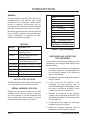
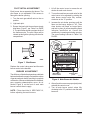
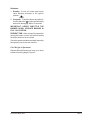
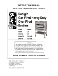
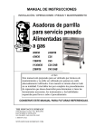
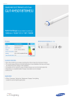
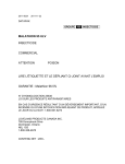
INSTALLATION &
OPERATION MANUAL
GAS FIRED BROILERS
E36W36
E43W36
E136W36
D
C
E
E S I GN
EV136W36
E236W36
E243W36
EC36
EC45
THE MONTAGUE CO.
R T IF I E D
Please read this manual completely before attempting to
install or operate this equipment! Notify carrier of damage.
Inspect all components immediately. See page 4.
RETAIN THIS MANUAL FOR FUTURE REFERENCE.
The MONTAGUE Company
1830 Stearman Ave. • P.O. Box 4954 • Hayward, CA 94540-4954 • Tel: 510/785-8822 • Fax: 510/785-3342
IMPORTANT FOR YOUR SAFETY
THE INSTALLATION INSTRUCTIONS CONTAINED HEREIN ARE FOR THE USE OF QUALIFIED
INSTALLATION AND SERVICE PERSONNEL ONLY. INSTALLATION OR SERVICE BY OTHER THAN
QUALIFIED PERSONNEL MAY RESULT IN DAMAGE TO THE UNIT AND/OR INJURY TO THE OPERATOR.
IF YOU SMELL GAS
1.
TURN OFF THE APPLIANCE AT THE GAS INLET COCK AND OPEN ALL DOORS
AND WINDOWS.
2.
DO NOT OPERATE ANY ELECTRICAL SWITCHES AND EXTINGUISH ALL
NAKED FLAMES.
3.
CONTACT THE LOCAL GAS AUTHORITY IMMEDIATELY.
THE FOLLOWING INSTRUCTIONS SHOULD BE READ CAREFULLY AS THE
MANUFACTURER CANNOT BE HELD RESPONSIBLE FOR ANY DAMAGE
TO PROPERTY, PERSONS OR ANIMALS CAUSED BY INCORRECT
INSTALLATION OR OPERATION OF THE APPLIANCE.
POST IN A PROMINENT LOCATION THE INSTRUCTIONS TO BE FOLLOWED
IN THE EVENT THE SMELL OF GAS IS DETECTED. THIS INFORMATION CAN
BE OBTAINED FROM THE LOCAL GAS SUPPLIER.
IN THE EVENT OF A POWER FAILURE, DO NOT ATTEMPT TO OPERATE THIS DEVICE.
IMPORTANT
IN THE EVENT A GAS ODOR IS DETECTED, SHUT DOWN UNITS AT MAIN
SHUTOFF VALVE AND CONTACT THE LOCAL GAS COMPANY OR GAS
SUPPLIER FOR SERVICE.
FOR YOUR SAFETY
DO NOT STORE OR USE GASOLINE OR OTHER FLAMMABLE VAPORS
OR LIQUIDS IN THE VICINITY OF THIS OR ANY OTHER APPLIANCE.
Improper installation, adjustment, alteration, service or
maintenance can cause property damage, injury or death. Read the
INSTALLATION, OPERATING AND MAINTENANCE INSTRUCTIONS
thoroughly before installing, servicing or operating this equipment.
SAVE THESE INSTRUCTIONS FOR FUTURE USE.
I&O-2
The MONTAGUE Company
TABLE OF CONTENTS
IMPORTANT FOR YOUR SAFETY .................................................................................................................. 2
INTRODUCTION ................................................................................................................................................ 4
GENERAL ................................................................................................................................................... 4
MODELS .................................................................................................................................................... 4
DATA PLATE LOCATION ........................................................................................................................... 4
SERIAL NUMBER LOCATION ................................................................................................................... 4
RECEIVING AND INSPECTING THE EQUIPMENT ................................................................................... 4
SPECIFICATIONS ...................................................................................................................................... 5
INSTALLATION ................................................................................................................................................. 6
STATUTORY REGULATIONS .......................................................................................................................... 6
CLEARANCES ........................................................................................................................................... 6
VENTILATING HOOD ................................................................................................................................. 6
VENTILATION AIR ...................................................................................................................................... 6
ASSEMBLY ................................................................................................................................................ 6
Legs...................................................................................................................................................... 6
Ceramic Radiants ................................................................................................................................ 7
LOCATION .................................................................................................................................................. 7
SITING ........................................................................................................................................................ 7
BATTERY ARRANGEMENT ...................................................................................................................... 7
Setting In Place ................................................................................................................................... 7
Floor Mounted Ranges ......................................................................................................................... 8
GAS SUPPLY ............................................................................................................................................ 8
GAS CONNECTION .................................................................................................................................... 8
GAS PRESSURE REGULATOR ................................................................................................................ 9
Adjustment Procedure ....................................................................................................................... 10
PILOT INITIAL ADJUSTMENT .................................................................................................................. 11
BURNER ADJUSTMENT .......................................................................................................................... 11
OPERATION ................................................................................................................................................... 12
GENERAL ................................................................................................................................................. 12
OPERATING CONTROLS ........................................................................................................................ 12
Gas Control ........................................................................................................................................ 12
Lighting/Relighting Pilot and Main Burner .................................................................................. 12
Shutdown ..................................................................................................................................... 13
Grid Height Adjustment ..................................................................................................................... 13
GENERAL MAINTENANCE ............................................................................................................................ 14
GENERAL CLEANING ............................................................................................................................. 14
Daily ................................................................................................................................................... 14
PAINTED SURFACES .............................................................................................................................. 14
Exterior ............................................................................................................................................... 14
Interior ................................................................................................................................................ 14
STAINLESS STEEL SURFACES ............................................................................................................. 14
VENTILATION ........................................................................................................................................... 15
SAFETY.................................................................................................................................................... 15
SERVICING .............................................................................................................................................. 15
C36 & C45 EXPLODED VIEW ........................................................................................................................ 16
C36 & C45 PARTS LIST ................................................................................................................................. 17
36W36 & 43W36 EXPLODED VIEW .............................................................................................................. 18
36W36 & 43W36 PARTS LIST ....................................................................................................................... 19
GAS FIRED BROILERS
I&O-3
INTRODUCTION
GENERAL
The gas broilers covered in this manual are
manufactured for use with the type of gas
indicated on the nameplate. Some models
include a cabinet, conventional oven or
convection oven. Ovens are covered in separate
manuals. This manual only covers the broiler.
Montague gas broilers are produced with the
best possible material and workmanship.
Proper installation is essential for safe,
efficient, trouble-free operation.
MODELS
MODEL
CONSISTS OF
E36W36
Cabinet Base Broiler with
Warming Oven
E43W36
Cabinet Base Broiler with
Warming Oven
E136W36
Broiler with Conventional
Oven and Warming Oven
EV136W36
Broiler with Convection Oven
E236W36
Double Broiler
E243W36
Double Broiler
EC36
Broiler Only
EC45
Broiler Only
DATA PLATE LOCATION
The Data Plate is located on the front left of the
unit, at the level of the Control Valve panel.
SERIAL NUMBER LOCATION
Always have the serial number of your unit
available when calling for parts or service.
The serial number is on the nameplate that
also includes the model number. A typical
identification plate is shown in Figure 1.
MODEL:
SERIAL NO.:
HEAT INPUT:
kW
CATEGORY:
SUPPLY PRESSURE:
mbar
GAS:
mbar
SET PRESS:
ELECTRICAL
V
Hz
Ph
W
COUNTRY:
P.I.N.:
GAS CATERING EQUIPMENT
SALAMANDER - TYPE A
THE MONTAGUE COMPANY
HAYWARD, CALIFORNIA USA
Figure 1. Typical Nameplate
RECEIVING AND INSPECTING
THE EQUIPMENT
Care should be taken during unloading so the
equipment is not damaged while being moved
into the building.
1. Visually inspect the exterior of the package
and skid or container. Any damage should
be noted and reported to the delivering
carrier immediately.
2. If damaged, open and inspect the contents
with the carrier.
3. In the event that the exterior is not
damaged, yet upon opening, there is
concealed damage to the equipment, notify
the carrier. Notification should be made
verbally as well as in written form.
4. Request an inspection by the shipping
company of the damaged equipment. This
should be done within 10 days from receipt
of the equipment.
5. Freight carriers can supply the necessary
damage forms upon request.
6. Retain all shipping materials until an
inspection has been made or waived.
I&O-4
The MONTAGUE Company
SPECIFICATIONS
Table A: Heat Input
NO. BURNERS
(broiler only)
G20 @ 20 mbar
kW
G31 @ 37 mbar
kW
TOTAL
kW
E36W36
2
123,000 ea.
123,000 ea.
24.6
E43W36
3
123,000 ea.
123,000 ea.
36.9
E136W36
2
123,000 ea.
123,000 ea.
36.3
EV136W36
2
123,000 ea.
123,000 ea.
36.3
E236W36
4
123,000 ea.
123,000 ea.
49.2
E243W36
6
123,000 ea.
123,000 ea.
73.8
EC36
2
123,000 ea.
123,000 ea.
24.6
EC45
3
123,000 ea.
123,000 ea.
36.9
MODEL
Table B: Setting Pressure/Injector Size
Manifold Pressure
Orifices
G20:
15 mbar
Fixed for specified gas type
G31:
25 mbar
G20:
mm (#32 DMS)
G30:
25 mbar
G31:
mm (#47 DMS)
Gas Inlet Size:
3/4" NPT at lower left rear (all
models)
NOTE: The pressure must be measured at the pressure test nipple located on
the manifold pipe with the burner lit.
Table C: Aeration Shutter/Pilot Flame Settings
G30 @ 30 mbar
G31 @ 37 mbar
mm
mm
mm
PILOT
FLAME
LENGTH
mm
E36W36
25
32
32
12.5
E43W36
25
32
32
12.5
E136W36
25
32
32
12.5
EV136W36
25
32
32
12.5
E236W36
25
32
32
12.5
E243W36
25
32
32
12.5
EC36
25
32
32
12.5
EC45
25
32
32
12.5
MODEL
2nd FAMILY, GROUP H
G20 @ 20 mbar
GAS FIRED BROILERS
3rd FAMILY, GROUP 3+
I&O-5
INSTALLATION
CAUTION: Provision must be made to
assure adequate air supply to unit for
proper burner operation.
STATUTORY REGULATIONS
The installation of this appliance must be carried
out by a competent person and in accordance
with the relevant regulations, standards, codes
of practice and the related publications of the
country of destination.
CLEARANCES
The following are minimum clearances from
combustible and noncombustible materials.
Location
Combustible
Construction
Noncombustible
Construction
Back Wall
152 mm
0 mm
Left Side
152 mm
0 mm
Right Side
152 mm
0 mm
With 152 mm legs: Suitable for installation on
combustible floors.
NOTE 1: The room containing the appliance
is required to have a permanent air vent. The
minimum effective area of the vent is related
to the maximum rated heat input of the
appliance and shall be 4.5 cm2 per kW in
excess of 7 kW.
NOTE 2: Air vents should be of such a size
to compensate for the effects of any extract
fan in the premises.
It is also necessary that sufficient room air
ingress be allowed to compensate for the amount
of air removed by the ventilating system.
Otherwise, a subnormal atmospheric pressure
will occur which may interfere with burner
performance or may extinguish the pilot flame.
In case of unsatisfactory broiler performance
check with the exhaust fan in the “OFF” position.
This appliance is to be installed with sufficient
ventilation to prevent the occurance of
unacceptable concentrations of substances
harmful to health in the room in which it is
installed.
Without legs: For use with special insulated
base on noncombustible floors only.
VENTILATING HOOD
The broiler(s) must be installed under a properly
designed ventilating hood. The hood should
extend at least 152 mm beyond all sides of the
unit. The hood should be connected to an
adequate mechanical exhaust system.
VENTALIATION AIR
The following notes are intended to give general
guidance. For detailed recommendations, refer
to the applicable code(s) in the country of
destination.
I&O-6
ASSEMBLY
Uncrate broiler as near to final location as
possible. For easier and lighter handling of broiler,
remove grids, grid frame, drip tray and grease
container. Remove all packing materials and
accessories from broiler interior.
Legs
Some broilers are mounted on legs.
1. Screws the legs into the modular stand.
2. Tightly screw the complete leg assembly
into the mounting holes in the bottom of the
broiler at each corner. If the unit is intended
for curb installation, no legs are provided.
The curb must be noncombustible material.
The MONTAGUE Company
Ceramic Radiants
Ceramic radiants, Figure 2, are located on each
side of the burners. Ceramic end pieces are
installed at both ends of each burner assembly.
Five (5) ceramic radiants are installed on each
side of each burner with the pointed side facing
down and the holes facing up, Figure 3
TOP VIEW
Frame
2. Tilt ceramic radiant sideways to clear burner
and frame assembly, then lower radiant into
position with one flange resting on burner
ledge and one flange resting on frame edge.
3. Install the remaining ceramic radiants so
that five (5) ceramic radiants are located on
each side of the burner.
LOCATION
Burner
Adequate clearance for service and proper
operation must be provided at the front, top,
sides, and back. The combustion air openings
are provided in the front of the unit and must not
be obstructed.
Ceramic
radiants
Ceramic
ends
(5 each side)
(4)
FRONT VIEW
MO10031
SITING
The floor on which the range is to be sited must
be capable of adequately supporting the weight
of the appliance and any ancillary equipment.
Once in position check that the unit is level, both
front to back and side to side. Adjust if necessary,
using the adjusting foot on each leg.
Figure 2. Ceramic Radiants Positioning
BATTERY ARRANGEMENT
Carefully remove range from crate. Burner tie
wires and other packing material must be
removed from the unit. On stainless steel units,
the protective material covering the stainless
steel must be removed immediately after unit is
installed.
Setting In Place
Model Nos. E36W36, E43W36, E136W36 and
EV136W36.
MO10032
Figure 3. Ceramic Radiants
1. Insert ceramic end pieces at front and rear
of the burner frame. Four (4) are required for
each burner.
GAS FIRED BROILERS
I&O-7
Floor Mounted Ranges
1. Place the first unit in the exact position it will
occupy in the battery.
2. Using a carpenter’s level, level the unit frontto-rear and side-to-side. AN UNLEVELED
UNIT WILL ADVERSELY AFFECT
PEFORMANCE. Adjust as follows:
FLOOR INSTALLATION ON LEGS: Level
by turning foot on leg.
CURB INSTALLATION: Place shim under
the low side. This operation is important
since variations in floors and curbs are
common. Unless units are level, aligning the
gas supply manifold will be difficult and the
units will not fit together tightly.
3. Remove the valve panel from the broiler.
4. Move the next unit into position.
5. Engage union nut on manifold with male
fitting on next unit and draw up union nut
hand tight. Be sure appliances meet together
both front and rear. If manifolds do not align,
then units are not level. In extreme cases, it
may be necessary to loosen manifold bolts
and adjust.
6. Continue leveling and connecting gas supply
manifolds together until all appliances in
battery are connected.
7. Tighten manifold gas union. Use backup
wrench to prevent manifold from rotating.
FAILURE TO DO THIS MAY RESULT
IN DAMAGE TO THE PILOTS AND
GAS VALVES.
GAS SUPPLY
The local gas region should be consulted at the
installation planning stage in order to establish
the availability of an adequate supply of gas and
to ensure that the meter is adequate for the
required flow rate. The pipe work from the meter
to the appliances must be of appropriate size.
Where a number of appliances are installed in a
battery, no more than five should be served by
any one supply pipe.
All fixed (non-mobile) appliances MUST be fitted
with a manual gas cock upstream of the
I&O-8
appliance to provide a means of isolation for
servicing or cleaning. A union or similar means
of disconnection must be provided between the
gas cock and the appliance.
A manually operable valve must be fitted to the
gas supply to the kitchen to enable it to be
isolated in an emergency. Wherever practical,
this shall be located either outside the kitchen or
near an exit in a readily accessible position.
Where it is not practical to do this, an automatic
isolation valve system shall be fitted which can
be operated from a readily accessible position
near the exit.
At locations where the manual isolation valve is
fitted or the automatic system can be reset, a
notice MUST be fitted stating:
“ALL DOWNSTREAM BURNER AND PILOT
VALVES MUST BE TURNED OFF PRIOR TO
ATTEMPTING TO RESTORE THE SUPPLY.
AFTER EXTENDED SHUT OFF, PURGE
BEFORE RESTORING GAS.”
GAS CONNECTION
Before connecting the broiler(s) to the gas supply
line, be sure that all new piping has been cleaned
and purged to prevent any foreign matter from
being carried into the controls by the gas. In
some cases, filters or drops are recommended.
A separate gas shutoff valve must be installed
upstream from the gas pressure regulator
adjacent to the broiler and located in an
accessible area.
It is important that adequately sized piping be
run directly to the point of connection at the
broiler with as few elbows and tees as possible.
Consult your local gas company for proper
piping size and gas pressure. The size of the
pipe work supplying the appliance must not be
less than the inlet connection. Each broiler has
a 3/4" NPT manifold input located at the lower
left rear of the broiler, Figure 4. On dual broilers,
each broiler must have a separate regulator.
NOTE: Pipe joint compound or thread sealant
that is used should be resistant to action of
liquefied petroleum gases.
The MONTAGUE Company
3/4"
NPT
Gas inlet
MO10033
Figure 4. Gas Inlet
Install the gas pressure regulator with gas flowing
as indicated by the arrow on the regulator. The
arrow must be pointing in toward the unit. Use
pipe compound or thread sealant and carefully
thread regulator to pipe so that there is no cross
threading, etc., which could cause leakage.
1. Apply wrench only to the flat areas around
the pipe tapping at the end being threaded to
the pipe to avoid possible damage to the
regulator body which could result in leakage.
2. Connect the gas supply line from the service
gas shutoff valve to the inlet side of the gas
pressure regulator using 3/4" pipe. Avoid kinks
or sharp bends that could restrict gas flow.
NOTE: If flexible or semi-flexible connectors
are used, a CE listed flexible connector with
an I.D. equal to 3/4" pipe must be used.
Do not use a domestic
type flexible gas connector.
3. Turn gas shutoff valve on and carefully check
for gas leaks immediately. Do this before
attempting to operate the broiler.
Test all pipe joints for
leaks before operating broiler. This
includes all gas connections that may
have loosened during shipment. Use a
rich soap solution (or other accepted
leak tester) around all pipe connections
and all other joints. Do not use an open
flame. Absolutely no leakage should
occur, otherwise there is a danger of
fire or explosion depending upon
conditions. Do not use unit if leakage
is detected.
After piping has been checked for leaks, all
piping receiving gas should be fully purged to
remove air.
GAS PRESSURE REGULATOR
The broiler(s) is/are
designed for use with a gas pressure
regulator. The regulator(s) supplied with
this unit must be used.
FOR G20 GAS: This gas pressure regulator
is factory adjusted for 15 mbar manifold pressure.
The rated inlet pressure to the regulator is
3.45 kPa.
FOR G31 and G30 GAS: This gas pressure
regulator is factory adjusted for 25 mbar
manifold pressure. The rated inlet pressure to
the regulator is 3.45 kPa.
The broiler is equipped with fixed orifices for use
with a manifold pressure of 15 mbar for G20 gas
and 25 mbar for G31 and G30 gas.
Position the gas pressure regulator outside the
broiler as near to the unit as possible.
CAUTION: The gas pressure regulator
must be located out of the heat zone to
prevent damage to the regulator.
The whole of the gas installation, including the
meter, should be inspected, purged and tested
for soundness in accordance with the codes of
the country of destination.
GAS FIRED BROILERS
I&O-9
Adjustment Procedure
Do not allow untrained
personnel to maintain or service the gas
pressure regulator.
1. Before adjusting the regulator, check the
incoming gas line pressure into the regulator.
Incoming pressure must be 20 mbar for G20
gas, 37 mbar for G31 gas, or 30 mbar for
G30 gas.
2. If incoming pressure is not correct, have the
gas source checked and adjusted.
6. Connect a manometer to the pressure tap
provided on the broiler unit gas piping
manifold, Figure 6. Turn all gas taps to the
full on “O” position.
7. Check the manometer reading. The reading
must be 15 mbar for G20 gas, 25 mbar for
G31 gas, or 25 mbar for G30 gas, per
Table B on PAGE 5.
8. If incoming line pressure is not correct,
adjust the regulator. Remove the seal cap
on the top of the regulator.
9. Insert a blade-type screwdriver into the top
hole of the regulator.
3. Make sure that the regulator is mounted in
the horizontal position with the arrow pointing
in the direction of the gas flow. SEE PAGE
12, LIGHTING /RELIGHTING PILOT AND
BURNER.
10. Turn the adjustment screw clockwise to
increase the pressure, or counter clockwise
to decrease the pressure.
4. Remove the main burner control valve knobs,
Figure 5.
While watching the manometer, turn the
adjustment screw to set proper regulator outlet
pressure to the manifold.
D
C
E
D
C
E
E S I GN
E S I GN
THE MONTAGUE CO.
R T IF I E D
THE MONTAGUE CO.
R T I FI E D
Burner valve knobs
Manifold
Screws
MO10034
Manometer
connection
pressure tap
MO10035
Figure 6. Gas Pressure Tap
Figure 5. Control Valve Knobs
5. Remove the control valve panel by removing
two screws.
I&O-10
The MONTAGUE Company
PILOT INITIAL ADJUSTMENT
Each burner has a separate pilot burner. The
pilot flame is not adjustable. Pilot access is
through the broiler opening.
1. Turn the main gas shutoff valve to the on
position.
2. Light each pilot.
3. Ensure that each pilot burner has a steady
blue flame, Figure 7, per Table C on PAGE
5. The pilot flame should envelope the tip of
the thermocouple. The pilot flame can be
viewed up through the opening of the broiler
compartment.
1. Lift off the venturi cover to access the air
shutter for each main burner.
2. Turn on the main burner control valve for the
main burner to be adjusted by rotating the
main burner control valve fully counterclockwise to the “O” position.
3. Increase the air shutter openings until the
flame on the burner begins to “lift”. Then
close shutter until flame no longer floats,
and lock in place. A yellow streaming flame
indicates insufficient air. Correct this
condition by increasing air shutter opening.
The correct setting is shown in Table C on
PAGE 5.
Air shutters
Figure 7. Pilot Burner
E S I GN
THE MONTAGUE CO.
C
D
D
E
R T IF I E
Replace the control valve panel and the main
burner control valve handles.
BURNER ADJUSTMENT
The efficiency of the broiler depends on a delicate
balance between the supply of air and the volume
of gas at each main burner resulting in complete
combustion. Whenever this balance is disturbed,
poor operating characteristics occur. An air
shutter, Figure 8, on the front of each main
burner controls the air supply.
NOTE: Pilots should be lit, SEE PAGE 12,
before adjusting the main burners.
GAS FIRED BROILERS
Main burner
control valves
Control valve
panel
MO10038
Figure 8. Main Burner Air Shutter
4. After all main burners are properly adjusted,
reinstall the venturi cover.
5. Turn all main burner control valves fully
clockwise to the “O” position to turn the main
burner off.
I&O-11
OPERATION
GENERAL
This appliance has been classified as
commercial cooking equipment and must be
operated by qualified and/or professional
operating personnel.
The broiler and its parts
are hot. Use care when operating,
cleaning or servicing the unit.
CAUTION: Do not obstruct the flow of
combustion and ventilation air to the
broiler. Keep appliance area free and
clear of combustibles.
BURNER CONTROL: Used to turn the main
burner and pilot gas on or off. One control for
each burner.
GRID HEIGHT: The grid is set to the desired
cooking height by depressing the ball and
adjusting lever up or down.
Gas Control
Lighting/Relighting Pilot and Main Burner
1. Turn burner valve handle to off position and
wait five (5) minutes.
2. Push in the tap and turn it counter-clockwise
”.
to the ignition position “
3. Holding the tap fully in, light the pilot with a
match or taper.
OPERATING CONTROLS
In the event gas oder is
detected, shut down units at main gas
shutoff valve and contact the local gas
company or gas supplier for service.
The following controls are used for operation of
the broiler, Figure 9.
4. When the pilot is lit, continue to hold the tap
fully in for 20 seconds, then release it. If the
pilot goes out, wait for (5) minutes, then
repeat from step 1.
5. When the pilot is established, push the tap in
again and turn it counter-clockwise to the full
flame position “ ”, thus lighting the main
burner.
IMPORTANT: DO NOT THROTTLE THE
BURNER DOWN. BURNER MUST
OPERATE FULLY OPEN AT ALL TIMES.
E S I GN
THE MONTAGUE CO.
C
D
D
E
6. If pilot becomes extinguished, turn main
burner valve to the off position (fully
counterclockwise) and wait five (5) minutes
before relighting.
R T I FI E
Burner valve knobs
Grid height control
MO10039
Figure 9. Operating Controls
I&O-12
The MONTAGUE Company
Shutdown
1. Standby: To turn off, rotate main burner
valve handles clockwise to the ignition
”.
position “
2. Complete: To shut the burner and pilot off,
turn the dial to the “ ” symbol and the safety
device will disengage within 60 seconds.
IMPORTANT: NEVER THROTTLE THE
BURNER DOWN. OPERATE BURNER IN
FULL ON POSITION.
PREHEAT TIME - Allow at least 5 minutes after
turning the broiler on from cold, before loading
the broiler with food to be cooked
Check the grease container and drain frequently
during heavy use to prevent overflow.
Grid Height Adjustment
Depress black ball and move lever up or down
to desired cooking height, Figure 9.
GAS FIRED BROILERS
I&O-13
GENERAL MAINTENANCE
GENERAL CLEANING
PAINTED SURFACES
The broiler and its parts
are hot. Use care when operating,
cleaning or servicing the unit.
Lint and grease suspended in the air tend to
collect in passages. Therefore, air openings,
flue ways, and primary air openings, etc.,
should be periodically cleaned to prevent
clogging. The entire broiler should be given a
periodic general cleaning.
Allow the broiler to cool down before cleaning
exterior surfaces. Painted surfaces should be
cleaned using a mild soap and warm water
solution on a sponge or soft cloth.
Interior
Clean interior using a mildly abrasive cleanser
with a damp cloth or nylon cleaning pad.
Daily
Remove grid racks, drip deflector (below grid
rack), drip tray, and grease container. Thoroughly
wash with mild detergent or soap. Excessive
grease buildup may be removed by using a
mildly abrasive cleanser.
Grid
rack
Grease
container
Drip
tray
STAINLESS STEEL SURFACES
To remove dirt, grease or product residue from
stainless steel, use ordinary soap and water
(with or without detergent) applied with a sponge
or cloth. Dry thoroughly with a clean cloth.
To remove grease and food splatter, or
condensed vapors that have baked on the
equipment, apply cleanser to a damp cloth or
sponge and rub cleanser on the metal in the
direction of the polishing lines on the metal.
Rubbing cleanser as gently as possible in the
direction of the polished lines will not mar the
finish of the stainless steel. NEVER RUB WITH
A CIRCULAR MOTION.
Drip
deflector
MO10040
Figure 11. Items To Be Cleaned Daily
I&O-14
Exterior
Soil and burnt deposits which do not respond to
the above procedure can usually be removed by
rubbing the surface with SCOTCH-BRITE
scouring pads or STAINLESS scouring pads.
DO NOT USE ORDINARY STEEL WOOL as
any particles left on the surface will rust and
further spoil the appearance of the finish. NEVER
USE A WIRE BRUSH, STEEL SCOURING
PADS (EXCEPT STAINLESS), SCRAPER, FILE
OR OTHER STEEL TOOLS. Surfaces which
are marred collect dirt more rapidly and become
more difficult to clean. Marring also increases
the possibility of corrosive attack.
The MONTAGUE Company
To remove heat tint: Darkened areas
sometimes appear on stainless steel surfaces
where the area has been subjected to excessive
heat. These darkened areas are caused by
thickening of the protective surface of the
stainless steel and are not harmful. Heat tint can
normally be removed by the procedures
described above. Heat tint which does not
respond to this procedure calls for a vigorous
scouring in the direction of the polish lines, using
SCOTCH-BRITE scouring pads or a
STAINLESS scouring pad in combination with a
powdered cleanser. Heat tint action may be
lessened by not applying or by reducing heat to
equipment during slack periods.
VENTILATION
The area in which the appliance is installed must
be adequately ventilated to provide air for
combustion, removal of products of combustion
and removal of steam, etc. The use of a
mechanical extract system should be
considered.
SERVICING
If not installed,
operated and maintained in
accordance with the
manufacturer’s instructions, this
product could expose you to
substances in fuel or in fuel
combustion which can cause death
or serious illness and which are
known to the State of California to
cause cancer, birth defects or
other reproductive harm.
All personnel in the
workplace who may be subject to any
exposure of carbon monoxide must be
warned of such possible exposure. This
warning should be conveyed in a manner so
that it is clearly understood by the
employee, and the employee should be
asked if in fact he or she understands the
correct method of operation of the
equipment and that a risk of exposure exists
if the equipment is operated improperly.
To ensure efficient and safe operation of the
appliance it is recommended that servicing is
carried out at regular intervals, the frequency of
which will vary depending on the installation
conditions and usage (usually once per year is
adequate).
Servicing must be carried out by competent
persons in accordance with the law.
SAFETY
It is essential that the instructions in this booklet
are strictly followed for the safe and economical
operation of the equipment. If it is known or
suspected that a fault exists on the appliance,
then it must not be used until the fault has been
rectified by a competent person.
GAS FIRED BROILERS
I&O-15
C36 & C45 EXPLODED VIEW
7
8
6
5
4
3
2
1
I&O-16
The MONTAGUE Company
ITEM
PART NUMBERS
DESCRIPTION
C36
236W36
C45
243W36
1
2033-8
2033-8
KNOB, BLACK BALL
2
3504-1
3504-1
HANDLE, SLEEVE
3
1600-4
1600-4
GRID IRON, RIGHT
4
N/A
1602-0
GRID IRON, CENTER
5
1601-2
1601-2
GRID IRON, LEFT
6
2002-8
2002-8
HANDLE, VALVE, W/SET SCREW
7
11611-4
11611-4
CERAMIC, LARGE
7A
28387-8
28387-8
CERAMIC KIT
(10 ea. 11611-4 Large Ceramics; 4 ea. 11614-9 Ceramic insulators)
8
11614-9
GAS FIRED BROILERS
11614-9
INSULATOR, CERAMIC
I&O-17
36W36 & 43W36 EXPLODED VIEW
7
8
9
10
6
5
4
3
2
1
I&O-18
The MONTAGUE Company
ITEM
PART NUMBERS
DESCRIPTION
36W36
43W36
1
2033-8
2033-8
KNOB, BLACK BALL
2
3504-1
3504-1
SLEEVE
3
1601-2
1601-2
GRID IRON - RIGHT
4
N/A
1602-0
GRID IRON- CENTER
5
1601-2
1601-2
GRID IRON - LEFT
6
2002-8
2002-8
HANDLE, VALVE, W/SET SCREW
7
11611-4
11611-4
CERAMIC, LARGE
7A
28387-8
28387-8
CERAMIC KIT
(10 ea. 11611-4 Large Ceramics; 4 ea. 11614-9 Ceramic insulators)
8
11614-9
11614-9
CERAMIC INSULATOR
9
3173-9
3173-9
HANDLE
10
1604-7
1579-2
WIRE RACK
GAS FIRED BROILERS
I&O-19
The MONTAGUE Company
1830 Stearman Ave. • P.O. Box 4954 • Hayward, CA 94540-4954
Tel: 510/785-8822 • Fax: 510/785-3342
I&O-20
The MONTAGUE
Company
P/N: 42880-9
(5/08)