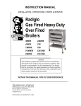
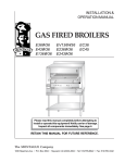
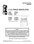
1
SERVICE & PARTS MANUAL
GAS FIRED
BROILERS
235W36
243W36
C36
C45
DE
C
36W36
43W36
136W36
V136W36
E
SIGN
THE MONTAGUE CO.
R TI F I E D
NOTICE
This manual is prepared for the use of Service Technicians
and should not be used by those not properly qualified.
This manual is not intended to be all encompassing. You
should read, in its entirety, the repair procedure you wish
to perform to determine if you have the necessary tools,
instruments and skills required to perform the procedure.
RETAIN THIS MANUAL FOR FUTURE REFERENCE.
The MONTAGUE Company
1830 Stearman Ave. • P.O. Box 4954 • Hayward, CA 94540-4954
Tel: 510/785-8822
Fax: 510/786-9931
1-888-875-2722
WWW.MONTAGUECOMPANY.COM
IMPORTANT FOR YOUR SAFETY
THIS MANUAL HAS BEEN PREPARED FOR PERSONNEL QUALIFIED TO INSTALL GAS EQUIPMENT,
WHO SHOULD PERFORM THE INITIAL FIELD START-UP AND ADJUSTMENTS OF THE EQUIPMENT
COVERED BY THIS MANUAL.
Qualified installation personnel are individuals, a firm, corporation, or company which either in person or through a
representative are engaged in and are responsible for:
A. The installation or replacement of gas piping or the connection, installation, repair or servicing of
equipment, who is experienced in such work familiar with all precautions required, and have complied with
all requirement of state or local authorities having jurisdiction. Reference: National Fuel Gas Code, ANSI
Z223.1, section 1.4, latest addenda.
B. The installation of electrical wiring from the electric meter, main control box or service outlet to the electric appliance.
Qualified installation personnel must be experienced in such work, be familiar with all precautions required and have
complied with all requirements of state and local authorities having jurisdiction. Reference: National Electric Code,
ANSI/NFPA No. 70, latest addenda.
THE BROILER(S) MUST BE INSTALLED IN ACCORDANCE WITH LOCAL CODES, OR IN THE ABSENCE OF
LOCAL CODES, WITH THE NATIONAL FUEL GAS CODE, ANSI Z223.1 LATEST ADDENDA, INCLUDING:
The appliance and its individual shutoff valve must be disconnected from the gas supply piping system during
any pressure testing of that system at test pressures in excess of 1/2 psig (3.45 kPa).
The appliance must be isolated from the gas supply piping system by closing its individual manual shutoff valve during
any pressure testing of the gas supply piping system at test pressures equal to or less than 1/2 psig (3.45 kPa).
POST IN A PROMINENT LOCATION THE INSTRUCTIONS TO BE FOLLOWED IN THE
EVENT THE SMELL OF GAS IS DETECTED. THIS INFORMATION CAN BE OBTAINED
FROM THE LOCAL GAS SUPPLIER.
IN THE EVENT OF A POWER FAILURE, DO NOT ATTEMPT TO OPERATE THIS DEVICE.
IMPORTANT
IN THE EVENT A GAS ODOR IS DETECTED, SHUT DOWN UNITS AT MAIN SHUTOFF
VALVE AND CONTACT THE LOCAL GAS COMPANY OR GAS
SUPPLIER FOR SERVICE.
FOR YOUR SAFETY
DO NOT STORE OR USE GASOLINE OR OTHER FLAMMABLE VAPORS OR LIQUIDS IN
THE VICINITY OF THIS OR ANY OTHER APPLIANCE.
WARNING
IMPROPER INSTALLATION, ADJUSTMENT, ALTERATION, SERVICE OR MAINTENANCE
CAN CAUSE PROPERTY DAMAGE, INJURY OR DEATH. READ THE INSTALLATION,
OPERATING AND MAINTENANCE INSTRUCTIONS THOROUGHLY BEFORE INSTALLING,
SERVICING OR OPERATING THIS EQUIPMENT.
SAVE THESE INSTRUCTIONS FOR FUTURE USE.
SM-2
The MONTAGUE Company
TABLE OF CONTENTS
SAFETY PRECAUTIONS ................................................................................................................................. 2
INTRODUCTION ................................................................................................................................................ 4
GENERAL ................................................................................................................................................... 4
Models .................................................................................................................................................. 4
Installation ............................................................................................................................................ 4
Operation ............................................................................................................................................. 4
Cleaning ............................................................................................................................................... 4
TOOLS ........................................................................................................................................................ 4
SPECIFICATIONS ...................................................................................................................................... 5
REMOVAL AND REPLACEMENT OF PARTS ................................................................................................ 6
COVERS AND PANELS ............................................................................................................................ 6
Venturi Cover ........................................................................................................................................ 6
Control Panel Cover ............................................................................................................................. 6
DRIP DEFLECTOR ..................................................................................................................................... 6
DRIP TRAY AND HORIZONTAL GREASE CONTAINER ........................................................................... 7
PILOT .......................................................................................................................................................... 7
Adjustment Valve ................................................................................................................................. 7
Pilot Assembly and Orifice .................................................................................................................. 7
MAIN BURNERS ........................................................................................................................................ 8
Burner Assembly, Orifice and Venturi ................................................................................................. 8
Burner Valve ......................................................................................................................................... 9
CARRIAGE POSITION HANDLE .............................................................................................................. 10
Black Ball Knob ................................................................................................................................. 10
Chrome Sleeve ................................................................................................................................... 10
Threaded Stud .................................................................................................................................... 10
Gear and Tube Assembly .................................................................................................................. 10
Compression Spring .......................................................................................................................... 10
Gear with Bracket .............................................................................................................................. 11
SERVICE AND ADJUSTMENT PROCEDURES ............................................................................................. 12
GAS PRESSURE REGULATOR ADJUSTMENT PROCEDURE ............................................................. 12
PILOT BURNER ADJUSTMENT PROCEDURE ....................................................................................... 12
CARRIAGE POSITION HANDLE ADJUSTMENT PROCEDURE ............................................................. 13
Handle Tension Adjustment ............................................................................................................... 13
CARRIAGE TENSION SPRING ADJUSTMENT PROCEDURE ............................................................... 13
TROUBLESHOOTING CHART ........................................................................................................................ 14
C36 & C45 EXPLODED VIEW ........................................................................................................................ 16
C36 & C45 PARTS LIST ................................................................................................................................. 17
36W36 & 43W36 EXPLODED VIEW .............................................................................................................. 20
36W36 & 43W36 PARTS LIST ....................................................................................................................... 21
CALIFORNIA REGULATIONS ........................................................................................................................ 23
GAS FIRED BROILERS
SM-3
INTRODUCTION
GENERAL
Installation
Montague Gas Broilers are manufactured for use with
the type of gas indicated on the nameplate (Natural
Gas or Propane).
Refer to the Installation and Operation Manual.
Models
Refer to the Installation and Operation Manual.
The following models are covered in this manual:
Cleaning
MODEL
CONSISTS OF
36W36
Cabinet-Base Broiler
with Warming Oven
43W36
Cabinet-Base Broiler
with Warming Oven
136W36
Broiler with Conventional Oven and
Warming Oven
V136W36
Broiler with Convection Oven
236W36
Double Broiler
243W36
Double Broiler
C36
Broiler Only on Stand
C45
Broiler Only on Stand
SM-4
Operation
Refer to the Installation and Operation Manual.
TOOLS
• Standard set of hand tools
• Gas leak detection equipment
• Gas pressure manometer
The MONTAGUE Company
SPECIFICATIONS
MODEL
NO. BURNERS
(broiler only)
NATURAL GAS
BTU/HR
PROPANE GAS
BTU/HR
TOTAL
BTU/HR
36W36
2
42,000 ea.
42,000 ea.
84,000
43W36
3
42,000 ea.
42,000 ea.
126,000
136W36
2
42,000 ea.
42,000 ea.
124,000
V136W36
2
42,000 ea.
42,000 ea.
129,000
236W36
4
42,000 ea.
42,000 ea.
168,000
243W36
6
42,000 ea.
42,000 ea.
252,000
C36
2
42,000 ea.
42,000 ea.
84,000
C45
3
42,000 ea.
42,000 ea.
126,000
Manifold Pressure
Orifices
Natural Gas:
6.0" W.C.
Fixed for specified gas type
Propane Gas:
10.0" W.C.
Natural Gas:
#33 DMS
Propane Gas:
#48 DMS
Gas Inlet Size:
3/4" NPT at lower left rear (all models)
GAS FIRED BROILERS
SM-5
PARTS REMOVAL AND REPLACEMENT PROCEDURES
Perform the following procedures to remove and
replace parts. To eliminate mistakes when ordering
parts, always provide the following information:
•
Model Number
•
Serial Number
1. Turn the control valves to the full off position, then
remove the control valve knobs.
2. Remove the two screws from the front of the
control panel.
These numbers are located on the nameplate.
CAUTION
Turn off the broiler gas valve and allow broiler
to cool before removing any components.
COVERS AND PANELS
Figure 2. Control Panel Cover
CAUTION
Turn off the gas supply at the manual shutoff
valve that is next to the broiler before
attempting to loosen any gas connections.
Venturi Cover
Removal of the venturi cover provides access to the air
shutter adjustments and main burner orifices.
1. Remove the two screws under the front edge of
the venturi cover.
2. Lift the venturi cover from the broiler.
DRIP DEFLECTOR
The drip deflector is located below the grid frame and
is angled toward the back of the broiler. Grease
dripping onto the drip deflector runs off the back edge
to the drip tray then flows forward into the horizontal
grease container.
1. Pull the grid frame assembly forward to the stop.
2. Remove the grids from the frame assembly.
3. Lift the back edge of the drip deflector to disengage
the drip deflector from the retaining latch.
4. Slide the drip deflector out at a downward angle.
5. When reinstalling the drip deflector, be sure to
engage the front end under the retaining latch.
Figure 1. Venturi Cover
Control Panel Cover
Removal of the control panel cover provides access to
the burner valves, pilot adjustment and carriage springs.
Figure 3. Drip Deflector
SM-6
The MONTAGUE Company
DRIP TRAY AND HORIZONTAL
GREASE CONTAINER.
The drip tray is located below the drip deflector.
Grease dripping onto the drip deflector runs off the
back edge to the drip tray then flows forward into the
horizontal grease container.
1. Pull the drip tray straight out the front of the
broiler.
2. Lift the horizontal grease container up and away
from the broiler.
NOTE: When dumping the contents of the
horizontal grease container, be sure to follow
appropriate regulations for disposing of grease.
NOTE: Make sure that the pipe joint compound or
pipe thread sealant that is being used is resistant
to the corrosive actions of liquefied petroleum gases.
5. Connect the gas line to the back of the valve.
6. Turn the main gas shutoff valve to broiler to the
ON position.
WARNING
ALL GAS JOINTS DISTURBED DURING
SERVICING MUST BE CHECKED FOR LEAKS.
CHECK WITH A SOAP AND WATER SOLUTION
(BUBBLES). DO NOT USE AN OPEN FLAME.
7. Light pilot and adjust pilot valve.
8. Reinstall control panel cover and control valve knobs.
Figure 4. Drip Tray and Grease Container
PILOT
Figure 5. Pilot Valve
Adjustment Valve
Pilot Assembly and Orifice
The pilot adjustment valves are located on the manifold
behind the control panel cover.
The pilot assembly is located adjacent to each burner.
The connection for the pilot assembly is accessed by
removing the venturi cover.
CAUTION
Turn off the gas supply at the manual shutoff
valve that is next to the broiler before
attempting to loosen any gas connections.
CAUTION
Turn off the gas supply at the manual shutoff
valve that is next to the broiler before
attempting to loosen any gas connections.
1. Remove the control panel cover as described
under COVERS AND PANELS to access the
pilot valve.
1. Remove the venturi cover as described in COVERS
AND PANELS.
2. Disconnect the gas line from the back of the valve.
2. Disconnect gas line from back of pilot assembly.
3. Unscrew the pilot valve from the manifold.
3. Unscrew the two screws attaching the pilot
assembly and pilot assembly bracket.
4. Install the new pilot valve with the adjustment
screw facing the front of the broiler.
GAS FIRED BROILERS
NOTE: Check condition of the pilot orifice and
replace if damaged.
SM-7
4. Install the new pilot assembly, orifice and pilot
assembly bracket.
5. Connect the gas line to the back of pilot assembly.
NOTE: Make sure that the pipe joint compound or
pipe thread sealant that is being used is resistant
to the corrosive actions of liquefied petroleum gases.
6. Turn the main gas shutoff valve to the broiler to
the ON position.
MAIN BURNERS
The connection for the burners is accessed by removing
the venturi cover. The burners are accessed by
removing the grids and carriage. The burner valves are
accessed by removing the control panel cover.
CAUTION
Turn off the gas supply at the main shutoff
valve that is next to the broiler before
attempting to loosen any gas connections.
WARNING
ALL GAS JOINTS DISTURBED DURING
SERVICING MUST BE CHECKED FOR LEAKS.
CHECK WITH A SOAP AND WATER SOLUTION
(BUBBLES). DO NOT USE AN OPEN FLAME.
7. Light pilot and adjust pilot valve.
8. Reinstall venturi cover, heat shield, insulation and
exterior top.
Burner Assembly, Orifice and Venturi
1. Remove the venturi cover as described in COVERS
AND PANELS.
2. Remove the ceramic radiants from each side of
the main burner to be replaced.
3. Loosen the set screw that attaches the main
burner to the venturi assembly.
4. Slide the main burner out of the broiler.
5. If the venturi or orifice is to be replaced, disconnect
the gas input to the venturi. Remove the gasket.
Replace the gasket every time the venturi or
burner is removed.
6. Loosen the lock nut so that the venturi can be
removed from the bracket.
Figure 6. Pilot Assembly Connection
Figure 8. Burner Pilot Assembly
7. Remove the orifice hex nut fitting from the venturi.
8. Remove the orifice from the hex nut fitting.
Figure 7. Pilot Assembly
SM-8
NOTE: Make sure that the pipe joint compound or
pipe thread sealant that is being used is resistant
to the corrosive actions of liquefied petroleum gases.
The MONTAGUE Company
9. Reassemble by reversing procedure.
WARNING
ALL GAS JOINTS DISTURBED DURING
SERVICING MUST BE CHECKED FOR LEAKS.
CHECK WITH A SOAP AND WATER SOLUTION
(BUBBLES). DO NOT USE AN OPEN FLAME.
3. Unscrew the burner valve from the manifold.
4. Install the new burner valve.
NOTE: Make sure that the pipe joint compound or
pipe thread sealant that is being used is resistant
to the corrosive actions of liquefied petroleum gases.
5. Connect the gas line to the back of the valve.
6. Turn the main gas shutoff valve to the broiler to the
ON position.
WARNING
ALL GAS JOINTS DISTURBED DURING
SERVICING MUST BE CHECKED FOR LEAKS.
CHECK WITH A SOAP AND WATER SOLUTION
(BUBBLES). DO NOT USE AN OPEN FLAME.
7. Light pilot.
Figure 9. Orifice Assembly
Burner Valve
8. Reinstall the control panel cover and control
valve knobs.
9. Turn burner valve full on and check that burner is
properly lit.
The burner valves are located on the manifold behind
the control panel cover.
CAUTION
Turn off the gas supply at the manual shutoff
valve that is next to the broiler before
attempting to loosen any gas connections.
1. Remove the control panel cover as described
under COVERS AND PANELS to access the
burner valve.
2. Disconnect the gas line from the back of the
burner valve.
GAS FIRED BROILERS
Figure 10. Burner Valve
SM-9
CARRIAGE POSITION HANDLE
The carriage position handle consists of the parts
shown in the following illustration and parts list.
Threaded Stud
1.
Turn off the burners.
2. Allow the broiler to cool to room temperature.
3. Remove the black ball knob by unscrewing it
(counterclockwise) from the threaded stud.
4. Remove the chrome sleeve from the tube/threaded
stud assembly.
5. Unscrew the threaded stud from the tube.
6. Reinstall the threaded stud by performing the
above steps in reverse order. Screw the threaded
stud about 1" into the threaded end of the tube.
Gear and Tube Assembly
1. Turn off the burners.
Figure 11. Carriage Position Handle
Item Part No. Description
A
B
C
D
E
F
02033-8
32756-5
03503-3
03506-8
03504-1
14442-8
Quantity
Knob, Black Ball
Compression Spring
Gear and Tube Assembly
Stud, Threaded
Sleeve, Chrome
Handle Bracket
1
1
1
1
1
1
2. Allow the broiler to cool to room temperature.
3. Remove the black ball knob by unscrewing it
(counterclockwise) from the threaded stud.
4. Remove the chrome sleeve.
5. Remove gear with bracket from the cabinet frame.
6. Slide the gear and tube assembly off the carriage
position handle arm.
7. Replace the gear and tube assembly by performing
the above steps in reverse order.
Black Ball Knob
Compression Spring
1. Remove the black ball knob by unscrewing it
(counterclockwise) from the threaded stud.
1. Turn off the burners.
2. Replace the black ball knob by screwing it
(clockwise) onto the threaded stud.
2. Allow the broiler to cool to room temperature.
3. Remove the black ball knob by unscrewing it
(counterclockwise) from the threaded stud.
Chrome Sleeve
4. Remove the chrome sleeve.
1. Turn off the burners.
5. Remove the threaded rod.
2. Allow the broiler to cool to room temperature.
6. Remove the spring from the tube and gear
assembly using needle nose pliers.
3. Remove the black ball knob by unscrewing it
(counterclockwise) from the threaded stud.
4. Remove the sleeve from the tube/threaded stud
assembly.
7. Replace the compression spring by performing
the above steps in reverse order.
5. Replace the chrome sleeve by placing the sleeve
onto the threaded stud.
SM-10
The MONTAGUE Company
Gear with Bracket
1. Turn off the burners.
2. Allow the broiler to cool to room temperature.
3. Raise grill to the top.
4. Remove all components of carriage position handle.
5. Remove the two screws and nuts that hold the
gear with bracket to the vertical frame rail.
6. Replace the gear with bracket by performing the
above steps in reverse order.
Figure 12. Gear with Bracket
GAS FIRED BROILERS
SM-11
SERVICE AND ADJUSTMENT PROCEDURES
When service is needed, contact a local service company, dealer or factory to perform mechanical
maintenance and repairs. These instructions are intended for use by competent service personnel.
CAUTION
Turn off the gas supply at the manual shutoff
valve that is next to the broiler unit before
attempting to loosen any gas connections.
GAS PRESSURE REGULATOR
ADJUSTMENT PROCEDURE
WARNING
DO NOT ALLOW UNTRAINED PERSONNEL
TO MAINTAIN OR SERVICE THE GAS
PRESSURE REGULATOR.
7. Insert a blade-type screwdriver into the top hole of
the regulator.
8. Turn the adjustment screw clockwise to increase
the pressure, or counterclockwise to decrease
the pressure.
9. While watching manometer, turn the adjustment
screw to set proper Regulator outlet pressure.
PILOT BURNER
ADJUSTMENT PROCEDURE
1. Light the pilot burner as described in the
Installation and Operation Manual.
Figure 14. Pilot Burner and Adjustment Valve
Figure 13. Gas Pressure Regulator
1. Before adjusting the regulator, check the incoming
gas line pressure. Incoming pressure before the
regulator must be 8.0" W.C. for Natural Gas, or
14.0" W.C. for Propane Gas.
2. If the pilot burner flame burns yellow, clean the
pilot burner orifice and the pilot burner in order to
ensure a steady blue flame. The orifice can be
cleaned by washing it in a solvent such as
trichloroethylene and/or blowing out with air.
2. If incoming pressure is not correct, have the gas
source checked and adjusted as necessary.
3. If the pilot burner flame still burns yellow, replace
the pilot burner orifice.
3. Make sure that the regulator is mounted in the
horizontal position with the arrow pointing in the
direction of the gas flow.
4. If the pilot flame does not extend 1/2" beyond the
outer edges of the pilot shield, or if it extends more
than 1/2" beyond the outer edges of the pilot
shield, an adjustment is necessary.
4. Connect a manometer to the pressure tap provided
on the manifold between the regulator and the
burner valves.
5. Check the manometer reading. The reading must
be 6.0" W.C. for Natural Gas, or 10.0" W.C. for
Propane Gas.
5. Remove the control panel cover as described in
COVERS AND PANELS.
6. Turn the pilot adjustment valve screw until 1/2"
flames are observed.
6. If incoming line pressure is not correct, adjust the
regulator. Remove seal cap on top of the regulator.
SM-12
The MONTAGUE Company
CARRIAGE POSITION HANDLE
ADJUSTMENT PROCEDURE
CARRIAGE TENSION SPRING
ADJUSTMENT PROCEDURE
The carriage position handle can be placed in a
number of vertical positions.
Carriage adjustments should be made with the grid
irons in place and allowance for product weight.
1. Grasp the black ball knob and press it in toward
the front control panel.
2. Raise or lower the carriage assembly to the
desired height.
3. Release pressure on the black ball knob to lock
the carriage assembly at the desired height.
DE
C
E
SIGN
R TI F I E D
Figure 16. Carriage Tension Spring
Figure 15. Carriage Position Handle
1. Locate the carriage tension spring adjustment
nut. The adjustment nut is accessible from the
front as follows:
Handle Tension Adjustment
Model Nos. 36W36 and 43W36:
Through lower compartment.
If carriage is difficult to move or will not stay in place,
the handle tension requires adjusting.
Model Nos. 136W36 and V136W36:
Behind valve panel.
1. Remove black ball knob and chrome sleeve.
Model Nos. C36, C45, 236W36 and 243W36:
Behind left and right front panels.
2. Turn threaded rod to the left to increase tension;
turn to the right to decrease tension.
2. Turn nut clockwise to increase tension or
counterclockwise to decrease tension.
3. If one side of the grid is lower than the other side,
turn the adjustment nut on the low side clockwise
to level the grid.
GAS FIRED BROILERS
SM-13
TROUBLESHOOTING CHART
SYMPTOM
Pilot burner flames are burning
yellow.
CAUSE
REMEDY
Gas too rich
Perform the Pilot Burner
Adjustment Procedure.
Clogged pilot air passages
Perform the Pilot Burner Orifice
Removal and Replacement
Procedure.
Pilot not properly adjusted
Perform the Pilot Adjustment Valve
Adjustment Procedure.
Pilot burner flames are less than or Pilot not properly adjusted
more than 1/2".
Perform the Pilot Burner
Adjustment Procedure.
Clogged pilot burner
Replace pilot burner.
Faulty pilot burner or orifice
Perform the Pilot Burner Removal
and Replacement Procedure or
Orifice Removal and Replacement
Procedure as applicable.
Faulty pilot valve
Perform the Pilot Burner Valve
Removal and Replacement
Procedure.
Burner flames burning yellow.
Incorrect gas pressure or
secondary air
Check gas pressure. Adjust or
clean air mixer.
One or more burner flames cannot
be adjusted.
Dirty Venturi passage
Perform the Main Burner Orifice
Removal and Replacement
Procedure.
Incorrect gas pressure
Check and adjust gas pressure.
Ceramics cracked, broken or
missing.
Replace damaged or missing
ceramics. See Installation &
Operation Manual.
Faulty burner valve
Perform the Main Burner Removal
and Replacement Procedure.
One or more pilot burner flames
cannot be adjusted.
SM-14
The MONTAGUE Company
SYMPTOM
The heat of one or more burners is
not uniform over the surface of the
ceramic tiles.
Carriage assembly will not stay at
a set height position.
Carriage assembly moves up and
down too easily or too hard.
GAS FIRED BROILERS
CAUSE
REMEDY
Clogged burner ports
Clean burner ports or perform the
Main Burner Removal and
Replacement Procedure.
Broken or missing ceramics
Replace broken or missing
ceramics.
Dirty venturi passage
Clean air mixer and venturi.
Wrong gas pressure
Check and adjust gas pressure.
Improper handle spring tension
adjustment
Perform the Handle Tension
Adjustment Procedure.
Worn or broken gear with bracket
Perform the Gear with Bracket
Removal and Replacement
Procedure.
Improper carriage spring tension
adjustment
Perform the Carriage Tension
Spring Adjustment Procedure.
SM-15
C36 & C45 EXPLODED VIEW
SM-16
The MONTAGUE Company
ITEM
PART NUMBERS
DESCRIPTION
C36
236W36
C45
243W36
1
12925-9
12925-9
PANEL, RIGHT SIDE
2A
25442-8
25442-8
FLUE, RIGHT SIDE
2B
25440-1
25440-1
FLUE, LEFT SIDE
2C
12610-1
15391-5
FLUE DEFLECTOR
3
15355-9
15385-0
EXTERIOR TOP
4
12923-2
12923-2
PANEL, LEFT SIDE
5
1100-2
1100-2
MANIFOLD
6
15367-2
15392-3
VALVE CONTROL PANEL
7
15211-0
15211-0
FRAME, BURNER ASSEMBLY
8
3511-4
3511-4
BURNER W/SET SCREW
9
11614-9
11614-9
INSULATOR, CERAMIC
10
11611-4
11611-4
CERAMIC, LARGE
10A
28387-8
28387-8
CERAMIC KIT
(10 ea. 11611-4 Large Ceramics; 4 ea. 11614-9 Ceramic insulators)
11A
15352-4
15383-4
HEAT SHIELD
11B
1430-3
1430-3
INSULATION
12
151 82-3
15295-1
FIRE BOX FRONT ASSEMBLY
13A
11769-2
11769-2
PILOT BURNER HEX COMP. FITTING
13B
2193-8
2193-8
PILOT BURNER ORIFICE – NAT
13C
2194-6
2194-6
PILOT BURNER ORIFICE – LP
14
3397-9
3397-9
BRACKET, ORIFICE
15
1280-7
1280-7
UNION, TUBING
16
1252-1
1252-1
TUBING, STEEL
17
6378-9
6378-9
BURNER, ORIFICE HEX COMP. FITTING
18A
4342-0
4342-0
BURNER, ORIFICE – LP #49
18B
17130-1
17130-1
BURNER, ORIFICE – NAT #32
19
20923-6
20923-6
GASKET, VENTURI
20
15216-1
15216-1
VENTURI, AIR MIXER ASSEMBLY
21
1224-6
1224-6
TUBING, ALUMINUM
22
3396-0
3396-0
BEARING, W/ ASSEMBLY
GAS FIRED BROILERS
SM-17
ITEM
PART NUMBERS
DESCRIPTION
C36
236W36
C45
243W36
23A
1601-2
1601-2
GRID IRON, LEFT
23B
N/A
1602-0
GRID IRON, CENTER
23C
1600-4
1600-4
GRID IRON, RIGHT
24
38331-7
38040-7
GRID FRAME ASSEMBLY
25
2549-1
3548-3
DRIP DEFLECTOR
26
4655-8
4657-4
CARRIAGE ASSEMBLY
27
2033-8
2033-8
KNOB, BLACK BALL
28
3504-1
3504-1
HANDLE, SLEEVE
29
3506-8
3506-8
THREADED ROD
30
3503-3
3503-3
TUBE AND GEAR ASSEMBLY
31
32756-5
32756-5
SPRING, HANDLE
32
14442-8
14442-8
HANDLE ASSEMBLY BRACKET
33
15244-7
15244-7
CARRIAGE SPRING MTG. BRACKET
34
1938-0
1938-0
EYE BOLT
35
3507-6
3507-6
GEAR, W/ANGLE BRACKET
36
34258-0
2034-6
CARRIAGE SPRING
37
28365-7
28365-7
CARRIAGE BOLT
38
13096-6
13101-6
STABILIZER UNIT ASSEMBLY
39
2002-8
2002-8
VALVE HANDLE W/SET SCREW
40
1000-6
1000-6
VALVE, PILOT
41
1007-3
1007-3
VALVE, BURNER
42A
6604-4
6604-4
HORIZONTAL GREASE CONTAINER – PTD
42B
6603-6
6603-6
HORIZONTAL GREASE CONTAINER – S/S
43
15246-3
15366-4
DRIP TRAY
44
13064-8
13065-6
STAND, MODULAR – PTD
45A
14605-6
14605-6
GAS PRESSURE REGULATOR – NAT.
45B
1040-5
1040-5
GAS PRESSURE REGULATOR – LP
SM-18
The MONTAGUE Company
NOTES
GAS FIRED BROILERS
SM-19
36W36 & 43W36 EXPLODED VIEW
SM-20
The MONTAGUE Company
ITEM
PART NUMBERS
DESCRIPTION
36W36
43W36
1
15168-8
15287-0
PANEL,BACK & SIDE
2
15233-1
32069-2
FALSE TOP, REAR
3A
15238-2
32075-7
FLUE, LEFT SIDE
3B
15239-0
32076-5
FLUE, RIGHT SIDE
4
15232-3
15232-3
FALSE TOP, FRONT
5
15609-4
31642-3
DOOR ASSEMBLY
6
3173-9
3173-9
HANDLE
7
15187-4
15305-2
GUARD RAIL ASSEMBLY
8
6137-9
6137-9
VALVE BRACKET
9
1073-1
15303-6
MANIFOLD
10
3544-0
3544-0
FRAME BURNER ASSEMBLY
11
3511-4
3511-4
BURNER W/HDW
12
11614-9
11614-9
CERAMIC INSULATOR
13
11611-4
11611-4
CERAMIC, LARGE
13A
28387-8
28387-8
CERAMIC KIT
(10 ea. 11611-4 Large Ceramics; 4 ea. 11614-9 Ceramic insulators)
14
15359-1
15359-1
HEAT SHIELD
15
15223-4
31645-8
OVEN BOTTOM LINER
16
1604-7
1579-2
WIRE RACK
17
15182-3
15295-1
FIRE BOX FRONT ASSEMBLY
18A
11769-2
11769-2
PILOT BURNER ASSEMBLY – NAT
18B
15432-6
15432-6
PILOT BURNER ASSEMBLY – LP
18C
2193-8
2193-8
ORIFICE – NAT
18D
2194-6
2194-6
ORIFICE – LP
19
3397-9
3397-9
ORIFICE BRACKET ASSEMBLY
20
1280-7
1280-7
UNION, TUBING
21
1252-1
1252-1
TUBING, STEEL
22
6378-9
6378-9
HEX COMP. FITTING ASSEMBLY
23A
6377-0
6377-0
ORIFICE – NAT
23B
2278-0
2278-0
ORIFICE – LP
24
20923-6
20923-6
GASKET, VENTURI
GAS FIRED BROILERS
SM-21
ITEM
PART NUMBERS
DESCRIPTION
36W36
43W36
25
15216-1
15216-1
VENTURI
26
1231 -9
1231 -9
TUBING, ALUMINUM
27A
1601-2
1601-2
GRID IRON - LEFT
27B
N/A
1602-0
GRID IRON- CENTER
27C
1601-2
1601-2
GRID IRON - RIGHT
28
3396-0
3396-0
BEARING ASSEMBLY
29
32376-4
38040-7
GRID FRAME ASSEMBLY/BEARING
30
3547-5
3548-3
DRIP DEFLECTOR
31
4660-4
4661-2
CARRIAGE ASSEMBLY
32
2033-8
2033-8
KNOB, BLACK BALL
33
3504-1
3504-1
SLEEVE
34
3506-8
3506-8
THREADED ROD
35
3503-3
3503-3
TUBE AND GEAR ASSEMBLY
36
23753-1
23753-1
SPRING, HANDLE
37
14442-8
14442-8
HANDLE ASSEMBLY BRACKET
38
15244-7
15244-7
BRACKET, CARRIAGE SPRING
39
1938-0
1938-0
EYE BOLT
40
34258-0
2034-6
CARRIAGE SPRING
41
3507-6
3507-6
GEAR, W/ANGLE BRACKET
42
28365-7
28365-7
CARRIAGE BOLT
43
13108-3
13109-1
STABILIZER UNIT ASSEMBLY
44
1000-6
1000-6
PILOT VALVE
45
1007-3
1007-3
VALVE
46
15267-6
15333-8
PANEL, VALVE CONTROL
47
2002-8
2002-8
HANDLE, VALVE, W/SET SCREW
48A
14605-6
14605-6
REGULATOR, GAS PRESSURE – NAT.
48B
1040-5
1040-5
REGULATOR, GAS PRESSURE – LP
49
4291-9
4291-9
GREASE DRAWER, 14" X 26 1/2" X 4"
SM-22
The MONTAGUE Company
WARNING
If not installed, operated and maintained in accordance with the
manufacturer’s instructions, this product could expose you to
substances in fuel or in fuel combustion which can cause death or
serious illness and which are known to the State of California to
cause cancer, birth defects or other reproductive harm.
The State of California enacted the California Safe Drinking Water and Toxic
Enforcement Act of 1986, (Prop. 65), which “prohibits any person in the course
of doing business from knowingly and intentionally exposing any individual to a
chemical known to the State of California to cause cancer or reproductive toxicity
without first giving clear and reasonable warning to such individuals.” The
Governor’s Scientific Advisory Panel added carbon monoxide to the list of
hazardous chemicals known to cause reproductive harm.
In order to establish full compliance with Proposition 65, we attached a yellow
warning label to each gas fired unit manufactured by the Montague Company.
Carbon monoxide would not be present in concentrations that would pose a
“significant risk” to the consumer when the equipment is installed, operated and
maintained as follows:
1. Installed in accordance with all local codes, or in the absence of local codes,
with the current National Fuel Gas Code Z223.1, Latest Addendum.
2. Installed under a properly designed and operating exhaust hood.
3. Connected to the type of gas for which the unit is equipped.
4. Proper appliance pressure regulator installed on the gas supply line and
adjusted for the manifold pressure marked on the rating plate.
5. Adequate air supply to the unit.
6. The equipment is operated in the manner intended using the proper utensil
for that type of appliance.
7. Keep the equipment clean and have it checked periodically.
8. Burner air adjustments, mechanical maintenance and repairs should be
performed by qualified service personnel.
If the equipment is not installed, operated and maintained in accordance with the
above, concentrations of carbon monoxide in excess of the established limits
could be present in the kitchen environment.
ALL PERSONNEL IN THE WORKPLACE WHO MAY BE SUBJECT TO
ANY EXPOSURE OF CARBON MONOXIDE MUST BE WARNED OF
SUCH POSSIBLE EXPOSURE. THIS WARNING SHOULD BE CONVEYED
IN A MANNER SO THAT IT IS CLEARLY UNDERSTOOD BY THE
EMPLOYEE, AND THE EMPLOYEE SHOULD BE ASKED IF IN FACT
HE OR SHE UNDERSTANDS THE CORRECT METHOD OF
OPERATION OF THE EQUIPMENT AND THAT A RISK OF EXPOSURE
EXISTS IF THE EQUIPMENT IS OPERATED IMPROPERLY.
GAS FIRED BROILERS
SM-23
SAVE THESE INSTRUCTIONS
FOR FUTURE USE.
The MONTAGUE Company
1830 Stearman Ave. • P.O. Box 4954 • Hayward, CA 94540-4954
Tel: 510/785-8822 • Fax: 510/786-9931
1-888-875-2722
WWW.MONTAGUECOMPANY.COM
SM-24
The BROILER_SM
MONTAGUE Company
(2/07)