1
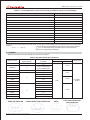
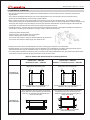
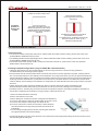
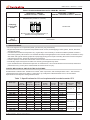
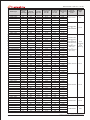
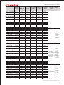
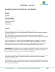
Solar Module
Installation Manual (IEC)
www.canadiansolar.com
INNOVATION I QUALITY I VALUE
1.0 GENERAL INFORMATION
This general manual provides important safety information relating to the installation, maintenance and handling of
CS-series solar modules. System users and professional installers should read this manual carefully and strictly follow
the instructions in the manual. Failure to follow these instructions may result in death, injury or property damage. The
installation of solar modules requires specialized skills and should only be performed by licensed professionals.
The word "module" or "PV module" used in this manual refers to one or more CS-Series Solar Modules.
Please retain this manual for future reference.
1.1 DISCLAIMER OF INSTALLATION MANUAL
The information contained in this manual is subject to change by Canadian Solar Inc. without prior notice. Canadian
Solar Inc. makes no warranty of any kind whatsoever, either explicitly or implicitly, with respect to the information
contained herein.
1.2 LIMITATION OF LIABILITY
Canadian Solar Inc. shall not be held responsible for damages of any kind, including without limitation bodily harm,
injury and property damage, relating to module handling, system installation, or compliance or non-compliance with
the instructions set forth in this manual.
2.0 SAFETY PRECAUTIONS
Warning: All instructions should be read and understood before attempting to install, wire, operate
and/or maintain the module. Module interconnects pass direct current (DC) when exposed to
sunlight or other light sources. Contact with electrically active parts of the module, such as terminals,
can result in injury or death, whether the module is connected or disconnected.
General Safety
·All installations must be performed in compliance with all applicable regional and local codes or other national or
international electrical standards.
·Wear suitable protection (non-slip gloves, clothes, etc.) to prevent direct contact with 30VDC or greater, and to
protect your hands from sharp edges during the installation.
·Use electrical insulated tools to reduce the risk of electric shock.
·Remove all metallic jewelry prior to installation to reduce the chance of accidental exposure to live circuits.
·Cover the front of the modules in the PV array with an opaque material to halt production of electricity when
installing or working with a module or wiring.
·Do not install or handle the modules when they are wet or during periods of high wind.
·Do not use or install broken modules.
·If the front glass is broken, or the back sheet is torn, contact with any module surface or the frame can cause electric
shock.
·There're no serviceable parts within the PV module. Do not attempt to repair any part of the module.
·Keep the junction box cover closed at all times.
·Do not disassemble a module or remove any module part.
·Do not artificially concentrate sunlight on a module.
·Do not connect or d isconnect modules when current from the modules or an external source is present.
3.0 MECHANICAL / ELECTRICAL SPECIFICATIONS
The module electrical ratings are measured under Standard Test Conditions (STC) of 1 kW/m 2 irradiance with an
AM1.5 spectrum, and cell temperature of 25℃. The detailed electrical and mechanical characteristics of Canadian
Solar Inc. crystalline silicon PV modules can be found in table 3 of this manual (see Annex). Main electrical
characteristics at STC also appear on each module label. The maximum system voltage for all module series is 1000 V.
Under certain conditions, a module may produce more current or voltage than its Standard Test Conditions rated
power. Accordingly, when determining component ratings and capacities, the module short-circuit current at STC
should be multiplied by 1.25, and a correction factor should be applied for the open-circuit voltage (see Table 1 below).
An additional 1.25 multiplier for the short-circuit current (for a total of 1.56) for sizing conductors and fuses may be
applicable, depending on your local regulations.
1
EN-Rev 2.2 Copyright
20 12 Apri. Canadian Solar Inc.
INNOVATION I QUALITY I VALUE
Table 1: Low temperature correction factors table for open-circuit voltage
Lowest Expected Ambient Temperature (℃/℉)
Correction Factor
24 to 20/76 to 68
1.02
19 to 15/67 to 59
1.04
14 to 10/58 to 50
1.06
9 to 5/49 to 41
1.08
4 to 0/40 to 32
1.10
-1 to-5/31 to 23
1.12
-6 to-10/22 to 14
1.14
-11 to-15/13 to 5
1.16
-16 to-20/4 to-4
1.18
-21 to-25/-5 to-13
1.20
-26 to-30/-14 to-22
1.21
-31 to-35/-23 to-31
1.23
-36 to-40/-32 to-40
1.25
Alternatively, a more accurate correction factor for the open-circuit voltage can be calculated based on the following
formula:
T is the lowest expected ambient temperature at the system location
C Voc=1- ∝Voc ×(25-T)
αVoc (%/℃) is the temperature coefficient of the selected module
(Refer to corresponding datasheet)
3.1 DIODES
·Diodes inside the junction box should meet requirements below:
Table 2: By-pass diode specifications
Number of
bypass diodes
Number of cells
CS6P-PE
5
12
CS6A-PE
5
CS5P
4
Module series
by diodes
Diode ratings
Voltage
Current
Diode type
≥12 A
10 (for 3 substrings)
9 (for 2 substrings)
24
CS5A
24
CS5T
20
CS6A
3
CS6P
16
20
CS6X
24
CS6H
18
CS5C
18
CS6E
18
CS6D
2
CS6C
≥10A
≥40V
≥15 A
Schottky
diodes
≥10A
18
18
CS5E
18
CS5H
18
·Diode configurations as below:
CS6P-PE /CS6A-PE
EN-Rev 2.2 Copyright
CS5A/CS5T/CS6A/CS6P/CS6X
20 12 Apri. Canadian Solar Inc.
CS5P
CS6H/CS5C/CS6E/CS6D/
CS6C/CS5E/CS5H
2
INNOVATION I QUALITY I VALUE
4.0 UNPACKING AND STORAGE
Precautions and General Safety
·Store modules in a dry and ventilated room.
·Do not allow children and unauthorized persons near the installation site or storage area of modules.
·Do not transport modules in an upright position.
·Unpacking module pallet with care and follow the unpacking steps marked on the pallet. Be careful
when unpacking, transporting and storing the modules.
·Do not carry a module by its wires or junction box. Carry a module by its frame with two or more people.
·Do not place modules on top of each other.
·Do not place excessive loads on the module or twist the module frame.
·Do not stand, step, walk and/or jump on the module.
·Do not drop or place objects on the modules (such as tools.)
·Do not mark the modules with sharp instrument. Particular attention should be taken to avoid module backsheet to
come in contact with sharp objects, as scratches may directly affect product safety.
·Do not leave a module unsupported or unsecured.
·Do not change the wiring of bypass diodes.
·Keep all electrical contacts clean and dry.
Product identification
·Each module is fitted with two identical barcodes (one on the laminate under the glass, the second on the module
frame) for its unique identification. Each module has a unique serial number with 13 digits.
·A nameplate is also affixed on the rear side of each module. This nameplate defines the model type, as well as the
main electrical and safety characteristics of the module.
5.0 MODULE INSTALLATION
Precautions and General Safety
·B efore installing modules, contact the appropriate authorities for site, installation and inspection
permission and requirement. .
·Check applicable building codes to ensure that the construction or structure (roof, facade, support,
etc.) can withstand the module system load.
·When installing modules, please ensure the assembly is mounted over a fire resistant roof covering
rated for the application. Canadian Solar modules have been listed as Class C according to UL790
standard.
·CS-series solar modules have been qualified for Application Class A (equivalent to Safety Class II
requirements). Modules rated under this class should be used in systems operating at voltage above
50V or power above 240W, where general contact access is anticipated.
·CAUTION: In any case DO NOT STAND OR STEP on the modules, as localized high loads may
induce severe micro-cracks at the cell level, which in turn may compromise module reliability.
Failure to comply with above caution will void Canadian Solar Inc warranty.
Environmental conditions
·The module is intended for use in general open climates, as defined in IEC 60721-2-1: Classification of
environmental conditions Part 2-1: Environmental conditions appearing in nature - temperature and humidity.
·Do not install modules near naked flames or flammable materials.
·Do not expose modules to artificially concentrated light sources.
·Do not immerse modules in water or constantly expose modules to water (either fresh or salt) (i.e. from fountains,
sea spray).
·Exposing modules to salt (i.e. marine environments) and sulfur (i.e. sulfur sources, volcanoes) risks module
corrosion.
Requirements of installation
·Ensure that the module meets the technical requirements of the system as a whole.
·Ensure that other systems components do not exert damaging mechanical or electrical influences on the modules.
·Modules can be wired in a series to increase voltage or in parallel to increase current. To connect in series, connect
cables from the positive terminal of one module to the negative terminal of the next module. To connect in parallel,
connect cables from the positive terminal of one module to the positive terminal on the next module.
·Quantity of bypass diodes provided can vary depending on model series.
3
EN-Rev 2.2 Copyright
20 12 Apri. Canadian Solar Inc.
INNOVATION I QUALITY I VALUE
·Connect the quantity of modules that match the voltage specifications of the inverters used in the system. Modules
must not be connected together to create a voltage higher than the permitted maximum system voltage, even under
the worst local temperature conditions (see table 1 for correction coefficients to apply for open-circuit voltage).
·A maximum of two strings can be connected in parallel without using over-current protection device (fuses)
incorporated in series within each string. Three of more strings can be connected in parallel if an appropriate and
certified over-current protection device is installed in series with each string.
·Similar electrical performance modules should be connected in same series to avoid or minimize mismatch effects
in arrays.
·To minimize risk in the event of an indirect lightning strike, avoid forming loops when designing the system.
·The recommended maximum series fuse rating is tabulated in annex.
·Modules should be firmly fixed in place in a manner suitable to withstand all expected loads, including wind and
snow loads. A minimum clearance of 6.5 mm (1/4 of an inch) or more between modules is required to allow for
thermal expansion of the frames.
·Small openings for water draining on the underside of the module should not be blocked after mounting.
Optimum orientation and tilt
·Find out the optimum orientation and tilt of the PV modules for your region to achieve the maximum annual yield.
Generation of maximum power occurs when sunlight shines perpendicularly onto the PV modules.
Avoid shading
·Even the slightest partial shading (e.g., from dirt deposits) will cause a reduction in yield. A module is considered
"shadow-free" if it is unobstructed across its entire surface for the whole year. Even on the shortest day of the year,
unobstructed sunlight can reach the module.
Reliable ventilation
·Sufficient clearance (at least 10 cm) between the module frame and the mounting surface is required to allow for
cooling air to circulate around the back of the module. This also allows for condensation or moisture to dissipate.
5.1 MODULE WIRING
Correct wiring scheme
·When designing the system, avoid forming loops (to minimize risk in the event of an indirect lighting strike). Make
sure that wiring is correct before starting up the system. If the measured open circuit voltage (Voc) and short-circuit
current (Isc) differ from the specifications, then there is a wiring fault.
Correct connection of plug connectors
·Make sure that the connection is safe and tight. The plug connector should not receive outer stress. The connector
should only be used to connect the circuit. It should never be used to turn the circuit on and off.
Use of suitable materials
·Use special solar cable and suitable plugs only (wiring should be placed in conduit that is sunlight-resistant or, if
exposed, should be sunlight-resistant) in accordance with local fire, building and electrical code. Ensure that they are
in perfect electrical and mechanical condition.
·The permitted type of solar cable is single conductor, 2.5-10 mm 2 (8-14 AWG), 90℃ wet rated, with proper
insulation to withstand the maximum possible system open-circuit voltage (such as TUV 2PfG1169 approved). The
conductor material should be copper only. Select a suitable conductor gauge to minimize voltage drop.
Cable protection
·Secure the cables to the mounting system using UV-resistant cable ties. Protect exposed cables from damage with
appropriate precautions (e.g. locate them within plastic conduit). Avoid exposure to the direct sunlight.
5.2 GROUNDING
·Although the modules are certified to safety class II, it is recommended that they be grounded and the module
installation complies with all local electrical codes and regulations.
·The earth grounding connection should be made by a qualified electrician.
2
·Connect module frames to each other using adequate grounding cables, the recommended size is 4-14mm (AWG
6-12) copper wires. Holes provided for this purpose are identified with a green label. All the junctions on the
conductive connection must be fixed.
·The bolts, nuts, flat washers, lock washers or other relevant hardware should be made of stainless steel.
EN-Rev 2.2 Copyright
20 12 Apri. Canadian Solar Inc.
4
INNOVATION I QUALITY I VALUE
·Grounding hardware is not provided by Canadian Solar Inc.
·Two specific grounding methods are recommended for Canadian Solar Inc. standard modules with 5 mm grounding
holes, as described below. Other grounding methods can be acceptable, provided they comply with all local electrical
codes and regulations. For some modules (SunTuile or NewEdge), standard grounding methods cannot be applied,
please refer to the most updated relevant technical notes (IM/IEC/SUNT-EN and IM/IEC/NEWE-EN).
Method A: Bolt + Nut with teeth + Cup washer.
Tighten the bolt using the nut
with teeth.
Attach wire between the flat
washer and cup washer. Place
cup washer (concave side up)
between frame and wire.
·A grounding kit with M5 size SS cap bolt, M5 size SS flat washer, M5 size SS cup washer, and M5 size SS nut (with
teeth) is used to attach a copper grounding wire to grounding hole pre-drilled on the frame (see picture above).
·Attach the wire between the flat washer and the cup washer. Ensure the cup washer is between the frame and wire
with concave side up to prevent corrosion due to dissimilar metal. Tighten the bolt securely using the SS nut with teeth.
A wrench may be used in this application. The tightening torque is 1 Nm.
Method B: Bolt + K-nut + Ring terminal (copper).
·Connect the grounding hardware (M5) to the grounding hole on the
frame as shown in the picture.
·A K-nut is used to penetrate the frame's anodizing (protective coating)
to create conductive connection.
·A torque moment of about 3 Nm should be used to fasten the
grounding parts to module frame.
6.0 MOUNTING INSTRUCTIONS
Standard modules
·For a clear understanding of module, please refer to the illustration of a standard module shown below:
5
Reference
Designation
1
Grounding holes
2
Junction box
3
Standard mounting holes
(long side)
4
4
6
1
Additional mounting holes
(high wind or snow loads)
5
Standard mounting holes
(short side)
6
Module frame
7
Cables and connectors
4
2
3
1
( )
7
3
( )
6
4
4
5
·The mounting design must be certified by a registered professional engineer. The mounting design and procedures
shall comply with local codes and all authorities having jurisdiction.
·Mounting hardware is not provided by Canadian Solar Inc.
·Standard modules can be mounted to a support structure with several approved methods, either using the mounting
holes located on the frame back flanges (see Example A), by means of clamps (see Example B) or by means of
insertion systems. For other installation hardware, please contact your local representative for further information.
Failure to use a recognized installation method will void Canadian Solar Inc warranty.
5
EN-Rev 2.2 Copyright
20 12 Apri. Canadian Solar Inc.
INNOVATION I QUALITY I VALUE
Example B:
Clamping on
Example A:
Bolting
·Use appropriate corrosion-proof fastening materials. All mounting hardware (bolt/spring washer/flat washer/nut)
should be stainless steel M6 size for bolting method (A), and M8 size for clamping method (B).
·Use a torque wrench for installation. The above figure shows methods of fastening module to support structure.
Tightening torques should respectively be within 4~6 Nm and 10~17 Nm for M6x1 (Example A) and M8x1.5 (Example
B) coarse thread bolts, depending on bolt class. Different recommendations from specific clamping hardware
suppliers should prevail.
·Standard modules can be installed in either landscape or portrait position, refer to the detailed instructions in
tables 3 to 6 for further guidance. Note that further countermeasures such the use of additional support bars should be
considered in heavy snow areas (> 2400 Pa), to avoid damage by the snow accumulating in the lowest row of modules.
·When the addition of a support bar is recommended to enhance mechanical stability and module long term
performance reliability, material of suitable resistance should be selected. Canadian Solar Inc recommends a
minimum thickness of 50mm for the bar. The support bar centerline should be positioned within 100 mm of the side
frame centerline (slight shift may be necessary to access module grounding hole).
6.1 METHOD A: BOLTING
·Modules should be bolted to support structures through mounting holes located in the frame's back flanges only. Do
not drill additional holes or modify the module frame. Doing so will void the warranty.
·Each module must be securely fastened at a minimum of 4 points on two opposite sides, using the most inner
mounting holes. If additional wind loads are anticipated for this installation, additional mounting points should be
used. System designer and installer are responsible for load calculations and for proper design of support structure.
·Modules should be bolted at the following hole locations depending on the configuration and load:
Table 3: Authorized attachments for bolting method
Uplift load ≤ 2400 Pa
Downforce load ≤ 2400 Pa
Uplift load ≤ 2400 Pa
2400 Pa ≤ Downforce load ≤ 5400 Pa
Use 4 standard mounting holes (long side)
Bolting on long
side frame
Mounting rails may run perpendicularly or parallel to the long side frame
Use 4 standard mounting holes (short side)
Use 4 standard mounting holes (short side).
An additional support bar should
be placed below the module.
Mounting rails may run parallel or
perpendicularly to the short side frame
Mounting rails should run parallel to the
short side frame
Bolting on short
side frame
(except for 6X
series)
EN-Rev 2.2 Copyright
20 12 Apri. Canadian Solar Inc.
Support bar
6
INNOVATION I QUALITY I VALUE
6.2 METHOD B: CLAMPING
·The mounting method has been qualified by Canadian Solar Inc but has NOT yet been certified by a third-party
organization.
·Top or bottom clamping methods will vary and are dependent on the mounting structures. Follow mounting
guidelines recommended by the mounting system supplier.
·Each module must be securely fastened at a minimum of 4 points on two opposite sides. The clamps should be
positioned according to the authorized position ranges defined in table 4. Install and tighten the module clamps to the
mounting rails using the torque stated by the mounting hardware manufacturer. System designer and installer are
responsible for load calculations and for proper design of support structure.
·Canadian Solar Inc. warranty may be void in cases where improper clamps or unsuitable installation methods are
found. When installing inter-modules or end type clamps, take measures so as:
1.Not to bend the module frame
2.Not to touch or cast shadow on the front glass
3.Not to damage the surface of the frame
4.To ensure the clamps overlap the module frame by at least 5 mm.
5.To ensure the clamps overlap length is at least 40 mm.
·Clamp material should be anodized aluminum alloy. Floating type clamps are not authorized.
·Clamp positions are of crucial importance for the reliability of the installation, the clamp centerlines must only be
positioned within the ranges indicated in table 4, depending on the configuration and load.
·For configurations where the mounting rails run parallel to the clamps installation side, precautions should be taken
to ensure the module frame (C-shape) overlap the rail by 15mm or more.
Table 4: Authorized attachments for clamping method
Uplift load ≤ 2400 Pa
Downforce load ≤ 2400 Pa
Uplift load ≤ 2400 Pa
2400 Pa ≤ Downforce load ≤ 5400 Pa
Use 4 clamps on the long side, the allowed range Use 4 clamps on the long side, the allowed range
depends on the module type.
depends on the module type.
A1
A1
B1
B1
A1
A1
B1
B1
Clamping on
long side frame
Clamping on
short side frame
Mounting rails may run perpendicularly or
parallel to the long side frame
Mounting rails may run perpendicularly or
parallel to the long side frame
Use 4 clamps on the short side, the allowed
range depends on the module type. Mounting
rails may run parallel or perpendicularly to
the short side frame
Use 4 clamps on the short side, the allowed
range depends on the module type. An
additional support bar should be placed
below the module.
A2
A2
A2
A2
A2
A2
A2
A2
Support bar
Mounting rails should run parallel
to the short side frame
7
EN-Rev 2.2 Copyright
20 12 Apri. Canadian Solar Inc.
INNOVATION I QUALITY I VALUE
For CS5P and CS6P series, an additional
support bar should be placed below the
module where download force above
1600Pa is expected. Mounting rails should
run parallel to the short side frame.
Clamping on
short side frame
A2
A2
A2
A2
Support bar
Authorized range for clamping as a function of model type:
Model type
CS5A
CS5P
CS6A
CS6P, CS5T
CS6X
A1 range (mm)
220 - 380
220 - 390
220 - 340
240 - 410
340 - 550
B1 range (mm)
330 - 400
330 - 400
270 - 330
340 - 410
410 - 490
A2 range (mm)
170 - 200
220 - 270
200 - 250
200 - 250
200 - 250
6.3 METHOD C: INSERTION SYSTEMS
·The mounting method has been qualified by Canadian Solar Inc but has NOT yet been certified by a third-party
organization.
·Insertion methods will vary and are dependent on the mounting structures. Follow mounting guidelines
recommended by the mounting system supplier.
·Each module must be securely maintained through all its length on two opposite sides. Install and tighten the
insertion profiles to the support structure using the hardware and instructions provided by the mounting system
manufacturer. System designer and installer are responsible for load calculations and for proper design of support
structure.
·Canadian Solar Inc. warranty may be void in cases where improper insertion systems or unsuitable installation
methods are found. When installing insertion profiles, take measures so as:
1.Not to bend the module frame
2.Not to touch or cast shadow on the front glass
3.Not to damage the surface of the frame
4.To ensure the insertion profiles overlap the module frame by at least 10 mm.
5.To ensure the module frame (C-shape) overlap the insertion profiles by
at least 15mm.
6.To ensure insertion profile thickness and tolerances suits module thickness
(40mm for most of Canadian Solar inc modules).
Table 5: Authorized attachments for insertion method
Uplift load ≤ 2400 Pa
Downforce load ≤ 2400 Pa
Uplift load ≤ 2400 Pa
2400 Pa ≤ Downforce load ≤ 4000 Pa
Use 2 insertion profiles running parallel to the long side frame.
Insertion
profile
on
long side
frame
For CS6X series, installations where the downforce load can reach up to a 5400Pa are authorized.
EN-Rev 2.2 Copyright
20 12 Apri. Canadian Solar Inc.
8
INNOVATION I QUALITY I VALUE
Use 2 insertion profiles running
parallel to the short side frame.
Use 2 insertion profiles
running parallel to the short
side frame.
Insertion
profile on
short side
frame
For CS5P and CS6P series, an
additional support bar should be
placed below the module where
download force above 1600Pa is
expected.
An additional support bar should be
placed below the module.
For CS6X series, installations where the
downforce load can reach up to a
5400Pa are authorized
6.4 SPECIFIC MODULE RANGES
Technical notes
·For SunTuile module frames (SunTuile series: CS5A-xxxMF and CS6A-xxxPF models), please refer to the most
updated IM/IEC/ SUNT-EN technical note.
·For NewEdge module frames (NewEdge series: CS5A-xxxMX and CS6P-xxxPX models), please refer to the most
updated IM/IEC/ NEWE-EN technical note.
·For frameless laminates (CS5A-xxxM-L model) mounted with Intrasole CL, please refer to the most updated
IM/IEC/INTCL-EN technical note.
Floating clamped configuration (only for CS5A-M-L laminate model)
·Clamping methods will vary and are dependent on the mounting structures. Follow mounting guidelines
recommended by the mounting system supplier.
·Each laminate must be securely fastened at a minimum of 8 points on the two opposite long sides. Clamp positions
are of crucial importance for the reliability of the installation, the clamp centerlines must only be positioned within the
ranges indicated in table 6. Install and tighten the module clamps to the mounting rails using the torque stated by the
mounting hardware manufacturer (in the absence of instructions, Canadian Solar Inc recommends a torque about
15Nm to 20Nm). System designer and installer are responsible for load calculations and for proper design of support
structure.
·Clamp material should be aluminum. EPDM type rubber or similar material should be used between the
laminate/clamp and laminate/mounting rail interfaces in order to prevent any damages to the laminate.
·Canadian Solar Inc. warranty may be void in cases where improper clamps or unsuitable installation methods are
found. When installing inter-modules or end type clamps, take measures so as:
1.Not to bend the laminate excessively
2.Not to cast shadow on the cells
3.Not to damage or scratch the surface of the glass and backsheet
4.To ensure the clamps overlap the module glass by at least 12 mm.
5.To ensure the clamps overlap length is at least 76 mm.
6.To ensure a minimum contact area of 40mm x 30mm between
the clamp and the mounting rails (rail thickness should be at
leat 40mm).
7.To use clamps of appropriate thickness, allowing the CS5A-M-L
4mm glass laminate to be fixed floatingly.
·Vertical (landscape) mounting of the laminate is not authorized unless appropriate safety hooks are used to secure
the laminate against sliding-off.
9
EN-Rev 2.2 Copyright
20 12 Apri. Canadian Solar Inc.
INNOVATION I QUALITY I VALUE
Table 6: Authorized attachments for CS5A-M-L laminate
Uplift load ≤ 2400 Pa
2400 Pa ≤ Downforce load ≤ 5400 Pa
Uplift load ≤ 2400 Pa
Downforce load ≤ 2400 Pa
Use 4 clamps on the long side, at the positions
defined below (tolerance ±20 mm).
A1=286mm
A2=334mm
A1
Clamping
on long side
frame
Not allowed.
A2
A2
Mounting rails may run perpendicularly or
parallel to the long side frame
Clamping on
short
side frame
Not allowed
7.0 MAINTENANCE
·Do not change the PV components (diode, junction box, plug connectors).
·Regular maintenance is required to keep modules clear of snow, bird droppings, seeds, pollen, leaves, branches,
dirt spots and dust.
·If a module has a sufficient tilt (at least 15 0), it generally is not necessary to clean the modules (rainfall will have a
self-cleaning effect). When there is a noticeable buildup of soiling deposits on the module surface, wash the PV array
with water and a gentle cleaning implement (a sponge) during the cool part of the day. Dirt must never be scraped or
rubbed away when dry, as this will cause micro-scratches.
·If snow is present, a brush with soft bristles can be used to clean the surface of the module.
·Periodically inspect the system to make sure all wiring and supports stay intact.
·If you need electrical or mechanical inspection or maintenance, it is recommended to have a licensed, authorized
professional carry out the job to avoid hazards of electric shock or injury.
ANNEX: MECHANICAL AND ELECTRICAL RATINGS
Standard Test Conditions are: irradiance of 1 kW/m 2, AM1.5 spectrum, and cell temperature of 25℃. The electrical
characteristics are respectively within±10 percent or [0; +5W] of the indicated values for Isc, Voc and Pmax.
Specifications are subject to change without notice.
Table 7: Specifications for CS-series photovoltaic modules under STC
Model Type
Maximum
power
Pmax<W>
Operating
Voltage
(Vmp) <V>
Operating
current
Imp <A>
Open Circuit Short Circuit Max. Series
Voltage
Current
Fuse Rating
Voc <V>
Isc <A>
<A>
CS5E-20P
20
17.4
1.15
21.7
1.25
3.00
CS5E-22P
22
17.7
1.24
22
1.33
3.00
CS5E-24P
24
18.20
1.32
22.19
1.43
3.00
CS5C-85M
85
17.8
4.78
22.1
5.12
10.00
CS5C-90M
90
18
4.99
22.3
5.34
10.00
CS5C-95M
95
18.3
5.19
22.4
5.52
10.00
CS5C-100M
100
18.5
5.39
22.5
5.74
10.00
CS5E-20M
20
17.6
1.14
21.9
1.23
3.00
CS5E-22M
22
17.9
1.23
22.2
1.31
3.00
CS5E-24M
24
18.4
1.31
22.4
1.41
3.00
CS5E-25M
25
18.7
1.34
22.6
1.43
3.00
CS5F-13M
13
17.4
0.75
21.5
0.83
3.00
CS5F-14M
14
17.5
0.8
21.8
0.88
3.00
CS5F-15M
15
17.8
0.84
22
0.92
3.00
EN-Rev 2.2 Copyright
20 12 Apri. Canadian Solar Inc.
Overall
Dimension
<mm>
Weight
<Kg>
620×28 4 ×25
2.10
12 1 3×547×40
8.00
620×28 4 ×25
2.10
446×284×25
1.50
10
INNOVATION I QUALITY I VALUE
Model Type
Maximum
power
Pmax<W>
Operating
Voltage
(Vmp) <V>
Operating
current
Imp <A>
Open Circuit Short Circuit Max. Series
Voltage
Current
Fuse Rating
Voc <V>
Isc <A>
<A>
CS5H-43M
43
17.8
2.41
22.2
2.57
5.00
CS5H-45M
45
18
2.5
22.3
2.67
5.00
CS5H-47M
47
18.3
2.57
22.4
2.75
5.00
CS5H-50M
50
18.7
2.68
22.6
2.86
5.00
CS5A-165P
165
34.9
4.73
43.7
5.09
10.00
CS5A-170P
170
35.2
4.83
43.9
5.20
10.00
CS5A-175P
175
35.4
4.94
44.1
5.31
10.00
CS5A-180P
180
35.7
5.04
44.2
5.41
10.00
CS5A-185P
185
36.0
5.14
44.3
5.54
10.00
CS5A-190P
190
36.2
5.25
44.4
5.61
10.00
CS5A-195P
195
36.6
5.32
44.6
5.70
10.00
CS5A-155M/MF/MX/M-L
155.0
35.1
4.42
43.6
4.80
10.00
CS5A-160M/MF/MX/M-L
160.0
35.1
4.55
43.8
4.91
10.00
CS5A-165M/MF/MX/M-L
165.0
35.3
4.68
44.1
5.01
10.00
CS5A-170M/MF/MX/M-L
170.0
35.6
4.78
44.3
5.12
10.00
CS5A-175M/MF/MX/M-L
175.0
35.8
4.89
44.4
5.23
10.00
CS5A-180M/MF/MX/M-L
180.0
36.1
4.99
44.6
5.34
10.00
CS5A-185M/MF/MX/M-L
185.0
36.4
5.09
44.6
5.46
10.00
10.00
CS5A-187.5MF
187.5
36.5
5.14
44.7
5.49
CS5A-190M/MF/MX/M-L
190.0
36.6
5.19
44.8
5.52
10.00
CS5A-195M/MF/MX/M-L
195.0
37.0
5.27
45.0
5.62
10.00
CS5A-200M/MF/MX/M-L
200.0
37.4
5.35
45.3
5.71
10.00
CS5A-205M
205.0
37.7
5.43
45.4
5.81
10.00
11
CS5P-215P
215.0
46.4
4.64
57.9
4.99
10.00
CS5P-220P
220.0
46.6
4.73
58.3
5.05
10.00
CS5P-225P
225.0
46.9
4.79
58.6
5.13
10.00
CS5P-230P
230.0
47.0
4.89
58.7
5.22
10.00
CS5P-235P
235.0
47.2
4.98
58.8
5.31
10.00
CS5P-240P
240.0
47.6
5.04
58.9
5.38
10.00
CS5P-245P
245.0
47.9
5.11
59.0
5.47
10.00
CS5P-250P
250.0
48.2
5.19
59.1
5.53
10.00
CS5P-255P
255.0
48.5
5.26
59.3
5.58
10.00
CS5P-260P
260.0
48.9
5.32
59.5
5.63
10.00
CS5P-200M
200.0
46.7
4.29
57.8
4.69
10.00
CS5P-205M
205.0
46.7
4.39
58.0
4.77
10.00
CS5P-210M
210.0
46.8
4.49
58.2
4.86
10.00
CS5P-215M
215.0
46.8
4.59
58.4
4.95
10.00
CS5P-220M
220.0
47.0
4.68
58.8
5.01
10.00
CS5P-225M
225.0
47.4
4.74
59.0
5.09
10.00
CS5P-230M
230.0
47.5
4.84
59.1
5.18
10.00
CS5P-235M
235.0
47.7
4.93
59.2
5.27
10.00
CS5P-240M
240.0
48.1
4.99
59.4
5.34
10.00
CS5P-245M
245.0
48.4
5.06
59.5
5.43
10.00
10.00
CS5P-250M
250.0
48.7
5.14
59.6
5.49
CS5P-255M
255.0
49.0
5.21
59.8
5.55
10.00
CS5P-260M
260.0
49.3
5.27
60.0
5.62
10.00
CS5T-130M
130.0
29.2
4.45
36.3
4.82
10.00
CS5T-135M
135.0
29.3
4.60
36.6
4.95
10.00
CS5T-140M
140.0
29.5
4.74
36.8
5.08
10.00
CS5T-145M
145.0
29.8
4.87
37.0
5.21
10.00
CS5T-150M
150.0
30.1
4.99
37.1
5.34
10.00
CS6H-26M
26
18.4
1.41
22.7
1.5
3.00
CS6H-24M
24
18.1
1.33
22.4
1.41
3.00
CS6H-22M
22
17.7
1.24
22.1
1.33
3.00
CS6H-20M
20
17.5
1.14
21.9
1.26
3.00
Overall
Dimension
<mm>
Weight
<Kg>
630x542x25
3.5
1595X801X40
or
1580 X808X40
15.30
1595X801X40
(standard Ed1)
or
1580 X808X40
15.30
(standard Ed2) (standard)
or
or
1639X827X17
17.00
(MF only)
(MX only)
or
1589X795X22.5
(M-L only)
1602X1061X40
20.30
1602X1061X40
20.30
1638X982X40
19.00
534X350X25
2.40
EN-Rev 2.2 Copyright
20 12 Apri. Canadian Solar Inc.
INNOVATION I QUALITY I VALUE
Maximum
power
Pmax<W>
Model Type
Operating
Voltage
(Vmp) <V>
Operating
current
Imp <A>
Open Circuit Short Circuit Max. Series
Voltage
Current
Fuse Rating
Voc <V>
Isc <A>
<A>
CS6H-26P
26
18.2
1.43
22.5
1.52
3.00
CS6H-24P
24
17.9
1.34
22.2
1.43
3.00
CS6H-22P
22
17.5
1.25
21.9
1.35
3.00
CS6H-20P
20
17.3
1.16
21.7
1.28
3.00
CS6D-60P
60
17.3
3.47
21.7
3.84
10.00
CS6D-65P
65
17.5
3.72
21.9
4.02
10.00
CS6D-70P
70
17.8
3.93
22.1
4.21
10.00
CS6D-75P
75
18.1
4.15
22.3
4.43
10.00
CS6D-60M
60
17.5
3.43
21.9
3.78
10.00
CS6D-65M
65
17.6
3.68
22.1
3.96
10.00
CS6D-70M
70
18.0
3.89
22.3
4.15
10.00
CS6D-75M
75
18.3
4.11
22.5
4.37
10.00
CS6E-60M
60
18.6
3.23
22.8
3.42
5.00
CS6E-55M
55
18.2
3.03
22.4
3.22
5.00
CS6E-50M
50
17.8
2.82
22.2
3.0
5.00
CS6E-45M
45
17.5
2.57
21.9
2.83
5.00
CS6E-60P
60
18.4
3.26
22.6
3.47
5.00
CS6E-55P
55
18.0
3.06
22.2
3.27
5.00
CS6E-50P
50
17.6
2.84
22.0
3.27
5.00
CS6E-45P
45
17.3
2.6
21.7
2.88
5.00
CS6C-120M
120.0
17.5
6.86
21.9
7.56
15.00
CS6C-125M
125.0
17.6
7.12
22.0
7.71
15.00
CS6C-130M
130.0
17.6
7.38
22.1
7.95
15.00
CS6C-135M
135.0
17.8
7.58
22.2
8.07
15.00
CS6C-140M
140.0
18.0
7.76
22.3
8.28
15.00
CS6C-145M
145.0
18.1
8.01
22.4
8.52
15.00
CS6C-120P
120.0
17.3
6.93
21.7
7.67
15.00
CS6C-125P
125.0
17.4
7.19
21.8
7.83
15.00
CS6C-130P
130.0
17.4
7.46
21.9
8.07
15.00
CS6C-135P
135.0
17.6
7.65
22.0
8.19
15.00
CS6C-140P
140.0
17.9
7.84
22.1
8.40
15.00
CS6C-145P
145.0
17.9
8.09
22.2
8.65
15.00
CS6P-200M
200.0
29.2
6.86
36.5
7.56
15.00
CS6P-205M
205.0
29.2
7.02
36.5
7.66
15.00
CS6P-210M
210.0
29.3
7.17
36.7
7.77
15.00
CS6P-215M
215.0
29.3
7.33
36.8
7.89
15.00
CS6P-220M
220.0
29.5
7.45
36.9
7.97
15.00
CS6P-225M/MM
225.0
29.7
7.58
37.0
8.07
15.00
CS6P-230M/MM
230.0
29.9
7.70
37.1
8.22
15.00
CS6P-235M/MM
235.0
30.1
7.82
37.2
8.34
15.00
CS6P-240M/MM
240.0
30.2
7.95
37.3
8.46
15.00
CS6P-245M/MM
245.0
30.3
8.09
37.4
8.61
15.00
CS6P-250M/MM
250.0
30.4
8.22
37.5
8.74
15.00
CS6P-255M/MM
255.0
30.5
8.35
37.7
8.87
15.00
CS6P-260M/MM
260.0
30.7
8.48
37.8
8.99
15.00
CS6P-265MM
265.0
30.9
8.61
37.9
9.11
15.00
CS6P-270MM
270.0
31.1
8.67
38.2
9.19
15.00
CS6P-165PE
165.0
27.7
5.96
35.6
6.73
15.00
CS6P-170PE
170.0
28.0
6.07
35.7
6.85
15.00
CS6P-175PE
175.0
28.2
6.21
35.8
7.00
15.00
CS6P-180PE
180.0
28.2
6.38
35.8
7.16
15.00
CS6P-185PE
185.0
28.5
6.49
35.9
7.27
15.00
CS6P-190PE
190.0
28.6
6.64
36.0
7.42
15.00
CS6P-195PE
195.0
28.7
6.80
36.1
7.54
15.00
CS6P-200P/PE/PX
200.0
28.9
6.93
36.2
7.67
15.00
CS6P-205P/PE/PX
205.0
28.9
7.09
36.2
7.78
15.00
EN-Rev 2.2 Copyright
20 12 Apri. Canadian Solar Inc.
Overall
Dimension
<mm>
Weight
<Kg>
534X350X25
2.40
783X666X35
6.50
783X666X35
6.50
608X666X35
5.10
608X666X35
5.10
1485X666X40
12.00
1485X666X40
12.00
1638X982X40
19.00
(Standard)
or
19.50
(MM Only)
19.00
(standard)
or
20.50
1638X982X40 (PX only)
or
19.50
(PM Only)
12
INNOVATION I QUALITY I VALUE
Model Type
Maximum
power
Pmax<W>
Operating
Voltage
(Vmp) <V>
Operating
current
Imp <A>
Open Circuit Short Circuit Max. Series
Voltage
Current
Fuse Rating
Voc <V>
Isc <A>
<A>
CS6P-210P/PE/PX
210.0
29.0
7.25
36.4
7.89
15.00
CS6P-215P/PE/PX
215.0
29.0
7.40
36.5
8.01
15.00
CS6P-220P/PE/PM/PX
220.0
29.2
7.53
36.6
8.09
15.00
CS6P-225P/PE/PM/PX
225.0
29.4
7.65
36.7
8.19
15.00
CS6P-230P/PE/PM/PX
230.0
29.6
7.78
36.8
8.34
15.00
CS6P-235P/PE/PM/PX
235.0
29.8
7.90
36.9
8.46
15.00
CS6P-240P/PM/PX
240.0
29.9
8.03
37.0
8.59
15.00
CS6P-245P/PM/PX
245.0
30.0
8.17
37.1
8.74
15.00
CS6P-250P/PM/PX
250.0
30.1
8.30
37.2
8.87
15.00
CS6P-255P/PM/PX
255.0
30.2
8.43
37.4
9.00
15.00
CS6P-260P/PM/PX
260.0
30.4
8.56
37.5
9.12
15.00
CS6P-265PM
265.0
30.6
8.66
37.7
9.23
15.00
CS6P-270PM
270.0
30.8
8.75
37.9
9.32
15.00
CS6P-275PM
275.0
31.0
8.88
38.0
9.45
15.00
CS6A-160M
160.0
23.3
6.86
29.2
7.56
15.00
CS6A-165M
165.0
23.4
7.06
29.2
7.71
15.00
CS6A-170M
170.0
23.5
7.24
29.4
7.80
15.00
CS6A-175M
175.0
23.6
7.41
29.5
7.92
15.00
CS6A-180M
180.0
23.8
7.58
29.6
8.07
15.00
CS6A-185M
185.0
23.9
7.74
29.7
8.26
15.00
CS6A-190M/MM
190.0
24.1
7.87
29.8
8.38
15.00
CS6A-195M/MM
195.0
24.2
8.04
29.9
8.56
15.00
CS6A-200M/MM
200.0
24.3
8.22
30.0
8.74
15.00
CS6A-205MM
205.0
24.5
8.38
30.2
8.90
15.00
CS6A-210MM
210.0
24.6
8.54
30.3
9.06
15.00
CS6A-215MM
215.0
24.7
8.70
30.4
9.22
15.00
CS6A-135PE
135.0
22.3
6.05
28.5
6.82
15.00
CS6A-140PE
140.0
22.5
6.21
28.6
7.00
15.00
CS6A-145PE
145.0
22.7
6.41
28.7
7.19
15.00
CS6A-150PE
150.0
22.9
6.56
28.8
7.35
15.00
CS6A-155PE
155.0
22.9
6.76
28.8
7.51
15.00
CS6A-160P/PE/PX
160.0
23.1
6.93
28.9
7.67
15.00
CS6A-165P/PE/PF/PX/P-L
165.0
23.1
7.13
29.0
7.82
15.00
CS6A-170P/PE/PF/PX/P-L
170.0
23.2
7.32
29.2
7.92
15.00
CS6A-175P/PE/PF/PX/P-L
175.0
23.4
7.49
29.3
8.04
15.00
CS6A-180P/PE/PF/PX/P-L
180.0
23.5
7.65
29.4
8.19
15.00
CS6A-185P/PE/PF/PM/PX/P-L
185.0
23.7
7.82
29.4
8.39
15.00
CS6A-190P/PE/PF/PM/PX/P-L
190.0
23.9
7.95
29.6
8.50
15.00
CS6A-195P/PF/PM/PX/P-L
195.0
24.0
8.13
29.6
8.69
15.00
CS6A-200P/PM/PX
200.0
24.1
8.30
29.8
8.87
15.00
CS6A-205P/PM/PX
205.0
24.2
8.47
29.9
9.03
15.00
CS6A-210P/PM/PX
210.0
24.3
8.63
30.0
9.19
15.00
CS6A-215PM
215.0
24.5
8.78
30.2
9.35
15.00
CS6X-255P
255.0
34.8
7.33
43.7
7.95
15.00
13
CS6X-260P
260.0
34.9
7.45
43.8
8.04
15.00
CS6X-265P
265.0
35.1
7.55
43.9
8.10
15.00
CS6X-270P
270.0
35.3
7.65
44.1
8.19
15.00
CS6X-275P
275.0
35.5
7.76
44.1
8.31
15.00
CS6X-280P
280.0
35.6
7.86
44.2
8.42
15.00
CS6X-285P
285.0
35.8
7.96
44.3
8.53
15.00
CS6X-290P
290.0
35.9
8.08
44.4
8.64
15.00
CS6X-295P
295.0
36.0
8.19
44.5
8.76
15.00
CS6X-300P
300.0
36.1
8.30
44.6
8.87
15.00
CS6X-305P
305.0
36.3
8.41
44.8
8.97
15.00
Overall
Dimension
<mm>
Weight
<Kg>
15.30
(Standard)
or
1324X982X40
15.50
(MM Only)
15.30
(standard)
1324X982X40
or
(standard)
18.50
or
(PF Only)
1368X1008X17
or
(PF only)
15.50
or
(PM Only)
1318X976X22.5
or
(P-L only)
15.00
(P-L only)
1954X982X40
EN-Rev 2.2 Copyright
27.00
(4mm
Glass)
or
23.00
(3.2mm
Glass)
20 12 Apri. Canadian Solar Inc.
INNOVATION I QUALITY I VALUE
Model Type
Maximum
power
Pmax<W>
Operating
Voltage
(Vmp) <V>
Operating
current
Imp <A>
Open Circuit Short Circuit Max. Series
Voltage
Current
Fuse Rating
Voc <V>
Isc <A>
<A>
CS6X-255M
255.0
35.2
7.25
44.0
7.83
15.00
CS6X-260M
260.0
35.3
7.37
44.1
7.92
15.00
CS6X-265M
265.0
35.5
7.47
44.3
7.98
15.00
CS6X-270M
270.0
35.6
7.58
44.4
8.07
15.00
CS6X-275M
275.0
35.8
7.68
44.5
8.19
15.00
CS6X-280M
280.0
36.0
7.78
44.6
8.30
15.00
CS6X-285M
285.0
36.1
7.89
44.7
8.40
15.00
CS6X-290M
290.0
36.3
8.00
44.7
8.51
15.00
CS6X-295M
295.0
36.4
8.11
44.9
8.63
15.00
CS6X-300M
300.0
36.5
8.22
45.0
8.74
15.00
CS6X-305M
305.0
36.6
8.33
45.2
8.84
15.00
CS6X-310M
310.0
36.7
8.44
45.3
8.95
15.00
EN-Rev 2.2 Copyright
20 12 Apri. Canadian Solar Inc.
Overall
Dimension
<mm>
Weight
<Kg>
1954X982X40
27.00
(4mm
Glass)
or
23.00
(3.2mm
Glass)
14
Headquarters
545 Speedvale Avenue West,Guelph,
Ontario, Canada N1K 1E6
Tel: +1-519-837-1881 Fax: +1-519-837-2550
Email: [email protected]
Germany
Landsberger Strasse 94, 80339 Munich, Germany
Tel: +49 (0) 89-51 996 89-0
Fax: +49 (0) 89-51 996 89-11
Email: [email protected]
Italy
Via Vittoria Colonna 40, 00193 Rome, Italy
Tel: +39-06-6880-1085 Fax: +39-06-6830-0032
Email: [email protected]
Spain
c/ Josefa Valcarcel, 8. 2nd floor, E-28027 Madrid, Spain
Tel: +34 91 320 28 84
Fax: +34 91 320 84 38
Email: [email protected]
Australia
Unit 3B, North Rydelink Business Park 277-283 Lane Cove Road
Macquarie Park, NSW 2113, Australia
Tel: +61 (2) 9889 4395
Email: [email protected]
USA
12657 Alcosta Blvd, Suite 140, San Ramon, CA 94583
Tel: +1-925-866-2700 Fax: +1-925-866-2704
Email: [email protected]
Japan
Round-Cross Shinjuku 5-Chome 8F, 5-17 Shinjuku Shinjuku-ku,
Tokyo Japan 160-0022
Tel: 03-5291-8591 Fax: 03-5291-8596
Email: [email protected]
Korea
201, SK HUB Officetel, 708-26, Yeoksam-Dong, Kangnam-gu,
Seoul, Korea
Tel: (02) 539-7541 Fax: (02) 539-7505
Email: [email protected]
Singapore
101 Thomson Road, #15-03 United Square
Singapore 307591
Tel: +65 65729050 Fax: +65 62594690
China
199 Lushan Road, Suzhou New District, Jiangsu, China, 215129
Tel: +86 (512) 6690-8088
Email: [email protected]
www.canadiansolar.com