1
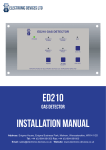
ZONE 1
ZONE 3
ZONE 2
ZONE 4
POWER
POWER
POWER
POWER
ALARM
ALARM
ALARM
ALARM
FAULT
TEST/
OVERRIDE
ALARM
ACCEPT
RESET
E ELECTRONIC
DEVICES
LIMITED
FAULT
TEST/
OVERRIDE
ALARM
ACCEPT
RESET
FAULT
TEST/
OVERRIDE
ALARM
ACCEPT
FAULT
RESET
TEST/
OVERRIDE
ALARM
ACCEPT
RESET
LEVEL DETECTOR TYPE ED830
manufactured in malvern, england
ED830
BILGE LEVEL ALARM CONTROL UNIT
INSTALLATION MANUAL
Address: Enigma House, Enigma Business Park, Malvern, Worcestershire, WR14 1GD
Tel: +44 (0)1684 891500 Fax: +44 (0)1684 891600
Email: [email protected] Website: www.electronic-devices.co.uk
INDEX
PAGE
GENERAL
SPECIFICATION
FuNCTION DIAGRAM
3
INSTALLATION - CONTROL PANEL
CONTROL PANEL DIMENSIONS DIAGRAM
4
INSTALLATION - FLOAT SWITCHES
FLOAT SWITCHES CONNECTION DIAGRAM
5
TESTING
ADJUSTMENTS (REACTION & RESET TIMES)
6
ZONE CIRCUIT, CONNECTION & ADJUSTMENTS DIAGRAM
7
ED830 IM REV 2 05.05.2015
ED830 - BILGE LEVEL ALARM CONTROL UNIT
2
GENERAL
The ED830 is a four zone bilge level alarm control unit designed to meet the MCA code of practice. Each of the four zones are
independent from each other with completely separate circuitry, switches, fuses, lamps etc.
Zone wiring is fault monitored with the aid of a 4K7Ω resistor, which must be fitted at the end of the line zone wiring in the form
of a end of line float switch. Both on and off delay times can be adjusted for each zone giving a pump run on facility and avoiding
nuisance alarms due to movement of the vessel.
Please note it is the responsibility of the end user to test the equipment regularly to ensure correct operation.
SPECIFICATION
Power input 12VDC or 24V DC
Typical Current consumption per zone:
in non alarm condition = 20mA
in alarm condition = 25mA
with short circuit wiring fault = 70mA
Ambient temperature range -25C to +55C
Note sounder, beacon and pump consumption not included.
ENCLOSURE DIMENSIONS
See diagram on page 4
FUNCTION DIAGRAM
POWER
ZONE 1
ZONE 3
ZONE 2
POWER
POWER
POWER
ALARM
ALARM
ZONE
ALARM
ALARM
ACCEPT
FAULT
ALARM
ACCEPT
RESET
E ELECTRONIC
DEVICES
LIMITED
TEST/
OVERRIDE
RESET
POWER
Illuminates amber when zone circuit
in short circuit fault.
ALARMZONE O/C
Illuminates amber when zone circuit
in open
ALARMcircuit fault.
FAULT
TEST/
OVERRIDE
Deactivates outputs connected to
alarm acceptable contacts
FAULT
ALARM
ACCEPT
RESET
TEST/
OVERRIDE
Illuminates red when zone detector
ZONE 4
in alarm condition
ZONE S/C
RESET
FAULT
Illuminates green when zone circuit
is powered on.
RESET
RESET
POWER
ALARM
ACCEPT
Resets the control panel to display
current condition.
TEST/
OVERRIDE
RESET
Activates all connected outputs
LEVEL DETECTOR TYPE ED830
manufactured in malvern, england
ALARM
FAULT
Illuminates green when power input is active.
Illuminates red when zone in alarm.
Illuminates amber when zone in fault.
Deactivates outputs connected to
alarm acceptable contacts
Resets the control panel to
display current condition.
Activates all connected outputs.
ED830 - BILGE LEVEL ALARM CONTROL UNIT
3
INSTALLATION - CONTROL PANEL
The control unit should be mounted in a convenient place for the operator, away from possible mechanical damage or ingress of
moisture and allowing the enclousure to swing open for ease of adjustment. (See diagram below)
N.B. If the only suitable position is exposed to dust or moisture then consideration should be given to having the enclosure to
I.P.54 standards or above. Contact Electronic Devices Ltd if you require advice or assistance.
The enclosure is opened by releasing the two screws on the right hand side of the enclosure and is secured to a wall or bulkhead
by four screws or bolts at the rear of the enclosure. Sufficient cable should be allowed so that the enclosure can swing open on
its hinges. The float switch should of course be mounted as low as possible in the bilge and will be impervious to attack from
both fresh and salt water, diesel oil, etc. It requires approx 30mm-40mm of travel of the float to cause operation of the switch.
275mm (283mm required for lid clearance)
LEVEL DETECTOR TYPE ED830
M3 mounting
holes 25mm
from edges.
(335mm required for lid clearance)
Cable gland entry holes.
283mm
ED830 - BILGE LEVEL ALARM CONTROL UNIT
4
INSTALLATION - FLOAT SWITCHES
CONNECTIONS
Ensure the intended supply voltage is suitable for the ED830 supplied, both 12Vdc and 24Vdc models are available.
The diagram below shows both single and multiple float switch per zone connection possibilities.
Multiple float switches
per zone. E.O.L must
be last float switch for
each zone
Single E.O.L float
switch per zone
LEVEL DETECTOR TYPE ED830
LEVEL DETECTOR TYPE ED830
Zone 1
ED735
E.O.L
Zone 2
ED735
E.O.L
Zone 3
ED735
E.O.L
ED830 - BILGE LEVEL ALARM CONTROL UNIT
Zone 4
ED735
E.O.L
Zone 1
Zone 2
Zone 3
Zone 4
ED735
E.O.L
ED735
Standard
ED735
Standard
ED735
Standard
ED735
Standard
ED735
E.O.L
ED735
Standard
ED735
E.O.L
ED735
E.O.L
5
TESTING
ALARM OUTPUT FUNCTIONS
The ED830 has three sets of voltage free contacts for each zone. One set for the pump, if fitted. The pump must have a current
consumption of less than 6A or be driven via a suitable external relay. The second set of contacts are for a low power xenon
beacon which could be fitted high on the vessel (e.g top of the mast) to attract attention whilst moored etc. The third set is for
electronic audio alarms, this is alarm acceptable, if this facility is not required the beacon or pump contacts can be used. All
peripheral equipment connected to the voltage free contacts should be supplied via external fuses or circuit breakers.
REGULAR TESTING
It is very important to check correct operation of all the bilge level alarm components regularly, and the tests below should be
performed at regular intervals. The magnetic circuit within the float allows either normally closed or normally open operation.
When the float is raised the circuit will be made and the 1K5Ω resistance will be connected across the zone line.
TESTING
On completion of installation it is important that both short circuit and open circuit faults are simulated and correct alarm operation
checked.
Check the operation of the unit by testing each float switch separately. Remove the float switch from its mounting bracket
and lower into a pail of water. The appropriate light should illuminate and the external items (sounders/beacons/pump) should
operate after a small delay set by adjustable ON delay. The sounder can be muted by pressing alarm accept. Remove the float
switch from the water, the beacon and pump will continue to operate. Press the reset button and after the short off delay the
pump and beacon will stop.The ON delay and pump RUN ON delay can be adjusted by rotating the potentiometers VR2 and VR3
respectively, clockwise to increase. See adjusting zone reaction time and reset time below.
TEST OUTPUT FUNCTIONS
The ED830 TEST/OVERRIDE button can be used to test the outputs on each individual zone.
ADJUSTMENTS - ON DELAY & PUMP RUN ON DELAY
ADJUSTING ZONE ON DELAY TIME
This adjustment determines the length of time needed before the pump and other outputs operate after the float switch is
submerged in water.
The on delay can be adjusted by rotating the VR2 potentiometer, clockwise to increase ON delay time and anti-clockwise to
decrease ON delay time.
ADJUSTING ZONE PUMP RUN ON DELAY TIME
This adjustment determines the length of time the pump and other outputs continue to operate after the float switch is no longer
submerged in water.
The pump run on (reset) delay can be adjusted by rotating the VR3 potentiometer, clockwise to increase pump run on delay and
anti-clockwise to decrease pump run on delay time.
ED830 - BILGE LEVEL ALARM CONTROL UNIT
6
ZONE CIRCUIT, CONNECTION & ADJUSTMENTS DIAGRAM
SPARK QUENCHED FOR PUMP
C
NO
NON ACCEPT
NC
C
NO
NC
Use VR3 to adjust RESET TIME
VR3
Clockwise turn increases pump RUN
ON delay time
Anti-clockwise turn decreases pump
RUN ON delay time
Use VR2 to adjust ON DELAY TIME
VR2
Clockwise turn increases ON delay time
Anti-clockwise turn decreases ON delay
time
VR3
VR2
SPARK QUENCHED FOR PUMP
C
NO
NON ACCEPT
NC
C
NON ACCEPTABLE
CONTACTS FOR PUMP
(VOLT FREE)
+VE
-VE
DC INPUT
+VE
NO
NC
NON ACCEPTABLE
CONTACTS
(VOLT FREE)
-VE
ZONE
C
NC
NO
ALARM CONTACTS
ACCEPTABLE
WARNING!
Ensure correct
voltage before
connecting
12VDC and
24VDC models
available
ACCEPTABLE
CONTACTS FOR
SOUNDER
(VOLT FREE)
CONNECT FLOAT
SWITCH(ES) WITH
E.O.L FLOAT
SWITCH AS LAST
FLOAT SWITCH
ED830 - BILGE LEVEL ALARM CONTROL UNIT
+VE
-VE
DC INPUT
+VE
-VE
ZONE
C
NC
NO
ALARM CONTACTS
ACCEPTABLE
7