1
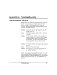
User Manual
ASeries A1650M
In-Line Mega Buffer
Parallel Parallel
The interfacing specialists
A1650M User Manual
Version 2.5
August 1998
COPYRIGHTS
All rights reserved. This document may not, in whole or part, be copied, photocopied,
reproduced, translated, or reduced to any electronic medium or machine readable form without
the express permission in writing from Alfatron Pty Ltd.
Copyright 1998 © Alfatron Pty Ltd
DISCLAIMER
Alfatron Pty Ltd has made every attempt to ensure that the information contained in this
document is accurate and complete. Alfatron Pty Ltd makes no representation or warranties of
merchantability or fitness for any particular purpose. Alfatron Pty Ltd reserves the right to make
changes to this document at any time, without notice. Therefore, Alfatron Pty Ltd assumes no
liability for damages incurred directly or indirectly from errors, omissions or discrepancies with
the hardware and the manual.
TRADEMARKS
All Company and Product names are trademarks of the Company or Manufacturer respectively.
WARRANTY
Alfatron warrants its products against defects in materials and workmanship for a period of one
year from receipt by the customer. All warranty is carried out on a return to depot basis unless
an alternative warranty coverage has been arranged.
WARRANTY EXCLUSIONS
The above warranty shall not apply to defects resulting from improper or inadequate
maintenance by the customer, unauthorised modifications or misues, operation outside the
environmental specifications for the product, damage due to power surges, lightening strikes or
any other phenomenon outside normal operational specifications.
Alfatron Pty Ltd ACN: 005 410 819
P.O. Box 4161
Unit 9/36 New St.
Ringwood VIC 3134
AUSTRALIA
A1650M User Manual
1.0
PRODUCT DESCRIPTION
The ASeries A1650M is a Centronics Parallel in-line mega buffer. This unit
will accept parallel data at over 200,000 characters per second through its
input port and store the data in the buffer for output.
The physical layout of the ASeries A1650M is as follows:
Transmit Data
(Green)
Receive Data
(Green)
Data Error
(Red)
Power
(Yellow)
Power Jack
Parallel INPUT
Parallel OUTPUT
Figure 1 - A1650M viewed from both ends and side
1.1
The A1650M data buffer accepts two 72-pin no-parity SIMMs of 4Mb,
8Mb, 16Mb or 32Mb size in any combination. It will automatically detect
and use the SIMMs which are installed, up to a total of 64Mb.
String Translation Option
The A1650S has an optional String Translation facility. This allows the unit to
be programmed with up to 128 different user defined strings using the
WINDOWS and DOS supplied software.
When the String Translation facility is used, all data passing through the A1650S
will be compared to the Input ‘string’. When a comparison is found, the Input
‘string’ will be replaced with the contents of the associated Output ‘string’ and
sent to the output port.
1
A1650M User Manual
2.0 INSTALLATION
Before installing the A1650M please make sure that the INPUT or OUTPUT
ports are selected correctly as required. The A1650M will not operate unless
the direction is correctly installed.
Insert the power plug into the power jack socket, next to the ‘Input’ connector.
Turn the power ON and observe the LEDs. The ‘Data Error’, 'Receive Data'
and 'Transmit Data' LEDs should light up and then extinguish within 2 seconds.
The 'Power' LED should then light up and remain alight, after this sequence
the A1650M is ready for operation.
Power OFF the A1650M and connect the correct cables between the A1650M
and the target devices. Use only cables which you know to have the correct
pin configurations to match the A1650M to your equipment. Cable requirements
and pin assignments are discussed in Sections 7 and 8.
WARNING:All devices must be powered OFF before connecting cables to
them.
Incorrect cabling may cause damage to either the A1650M or your equipment
and is not covered by warranty. If in doubt about pin configurations please
have them checked by your dealer.
2.1
Equipment 'Power ON' Sequence
The following 'Power ON' sequence is recommended once the A1650M is
installed in its operational environment:
The computer or data transmitting device should be powered ON first.
Next the A1650M should be powered ON and allowed to perform its self
diagnostics.
Finally the printer, plotter or other output device should be powered ON.
Note:
2
It is important that printers attached to the A1650M be connected and powered
on, otherwise data will be lost.
A1650M User Manual
3.0
CABLE REQUIREMENTS
Alfatron recommends the use of shielded cable with all of its products. Shielding
reduces EMI Radiation and improves noise immunity. This helps minimise
interference to other equipment and will improve communications reliability.
The recommended cable construction is as follows:
3.1
Take the shield (surrounding cable wires) and solder it to the Frame
Ground (FG) pin. If FG is not available, use Signal Ground (SG) but in
this case always use a separate wire for ground which is connected at
both ends.
The shield must be connected at both ends of the cable.
Typical Cables
To connect a PC to the Input port of the A1650M, use a pin-to-pin 25-wire
cable. Each connector on this cable will be DB-25 Male.
To connect a printer to the Output port of the A1650M, use a standard PC
Parallel Printer cable. This has a Male DB-25 connector at one end and a
Male 36-pin Centronics connector at the other.
3
A1650M User Manual
4.0 INTERFACE PORT PIN ASSIGNMENTS
4.1
Centronics Parallel INPUT Port
Pin Signal
Description
Pin Signal
Description
1
2
3
4
5
6
7
8
9
10
11
12
13
Input
Input
Input
Input
Input
Input
Input
Input
Input
Active Low
Active High
Pulled Low
Pulled High(4K7Ω)
14
15
16
17
18
19
20
21
22
23
24
25
Not Connected
Pulled High
-
Note:
4.2
(a)
(b)
Autofeed
Error
Not Connected
Ground
Ground
Ground
Ground
Ground
Ground
Ground
Ground
Ground
Strobe & Data lines are Pulled High to +5V via 1KΩ resistor.
Pins are Pulled Low to Ground.
Centronics Parallel OUTPUT Port
Pin Signal
Description
Pin Signal
Description
1
2
3
4
5
6
7
8
9
10
11
12
13
Output
Output
Output
Output
Output
Output
Output
Output
Output
Pulled High
Pulled High
Not Connected
Pulled High
14
15
16
17
18
19
20
21
22
23
24
25
Pulled High
Not Connected
-
Note:
4
Data Strobe
Data Bit 1
Data Bit 2
Data Bit 3
Data Bit 4
Data Bit 5
Data Bit 6
Data Bit 7
Data Bit 8
Acknowledge
Busy
Paper End
Select
Data Strobe
Data Bit 1
Data Bit 2
Data Bit 3
Data Bit 4
Data Bit 5
Data Bit 6
Data Bit 7
Data Bit 8
Acknowledge
Busy
Paper End
Select
(a)
Autofeed
I/O Error
Not Connected
Ground
Ground
Ground
Ground
Ground
Ground
Ground
Ground
Ground
Pins are Pulled High to +5V via 4K7Ω resistor.
A1650M User Manual
5.0
OPTIONAL A1650S -
STRING TRANSLATION SOFTWARE
The A1650S has a software option which allows the conversion of an incoming
data string to a different string on output. In total, 128 strings are available,
each up to 128 characters in length. The input and output strings may be
variable in length.
The strings are configured and modified using the ‘CFG1650S’ Setup software
supplied on a floppy disk. This software executes under DOS 2.00 or greater
on IBM PC/XT/AT/PS2 or compatibles.
Connect the Hardware
To use the ‘CFG1650S’ Setup software, the A1650S Port 1 must be connected
to the LPT1: or LPT2: parallel port on the computer. Make sure that the correct
cable is used to connect the A1650S to your computer, refer to Section 4 for
details.
Load the Software
Copy all the files, from the supplied disk, into a directory on your computer.
Change to the directory containing the software and type ‘CFG1650S’ at the
DOS prompt. The Main Menu will then be displayed.
5.1
MAIN MENU
To select options from the Main Menu, use the up/down arrow keys to highlight
the desired option and then press ‘Enter’. The options available at the main
menu are:
A1650S Communications performs the following tasks:
-
Download all setup parameters to the A1650S
Select the LPT: port of the computer
Print the setup parameters from the A1650S
File Operations allows the saving of the A1650S setup parameters to disk
and retrieval from disk.
Edit Sequences is used to modify all the Input and Output data strings.
Display Sequences is used to display all the Input and Output data strings.
Print Sequences is used to print all the Input and Output data strings.
Exit will exit this program and return to DOS.
5
A1650M User Manual
5.2
COMMUNICATIONS MENU
This menu provides all the necessary functions to communicate with the
A1650S. Before commencing any communications with the A1650S, ensure
that the port connection (LPT1: or LPT2:) is correct.
Download to A1650S
The Download Command is used to download all the ‘string definitions’ to the
A1650S. Normally the ‘string definitions’ will be downloaded after editing.
Select Port
Used to select the PC communication port as either LPT1: or LPT2:.
Print Setup
Print Setup is used to print the ‘string definitions’ currently held by the A1650S.
This option requires a printer to be connected to the output port (Port 2) of the
A1650S.
5.3
FILE OPERATIONS MENU
This menu provides all the necessary functions to store and retrieve, to disk,
‘string definitions’ used with the A1650S.
Select Path
Select Path is used to define the directory path used to search for A1650S
‘string definitions’ files. When the A1650S software is initially loaded, the
directory from which the software was started, will be used as default.
To select a directory path, highlight the Select Path option in the menu and
press ‘Enter’. The current directory will be displayed in a window on the screen.
Type in the desired directory and press ‘Enter’ to select. Alternatively, the
path may be changed using the up/down arrow keys and the path selected
using the ‘Enter’ key.
The current directory path is always displayed in the top left part of the screen.
Read File
Read File is used to retrieve ‘string definitions’ from a file in the current directory.
These definitions will reside in the current buffer of the A1650S software and
may be edited.
Write File
Write File is used to store ‘string definitions’ to a file in the current directory.
These definitions will be taken from the current buffer of the A1650S software.
6
A1650M User Manual
5.4
EDIT SEQUENCES FACILITY
Before editing, ‘string definitions’ must be uploaded or retrieved from a file.
Alternatively, editing may be done if all new ‘string definitions’ are to be entered.
There are two modes of editing ‘string definitions’, the HEX mode and the
ASCII mode. In HEX mode, enter the value of each character in HEX (ie 0..9
and A..F). In ASCII mode, enter the normal ASCII characters from the keyboard.
Using the Keyboard in the Edit Facility
Use the ‘+’ and ‘-’ keys to change the string number or type in the decimal
number and press ‘Enter’ to start editing.
Use ‘TAB’ key to change between modes. There are two cursors on screen,
one in the HEX window, the other in the ASCII window. Active mode is
indicated by flashing cursor.
To move within the string, use the ‘arrow’ keys. The ‘Delete’, ‘Insert’, ‘Home’
and ‘End’ keys can all be used.
The ‘PgUp’ and ‘PgDn’ keys change from the Input string to the Output
string.
The ‘F5’ key is used to delete from the current cursor position to the end of
the string.
Use the ‘F1’ key to change string numbers and use the ‘ESC’ key to exit
from the edit facility.
5.5
DISPLAY SEQUENCES FACILITY
This facility operates similarly to the Edit facility except that editing is not
allowed and the ‘PgUp’ and ‘PgDn’ keys are used to move between the different
string numbers.
5.6
PRINT SEQUENCES FACILITY
Print Facility prints the ‘string definitions’ from the A1650S software. The
computer print port is selected from this menu. ‘String definitions’ are printed
in HEX and ASCII formats.
7
A1650M User Manual
6.0 SPECIFICATIONS
CPU:
Parallel Port:
Data Buffer:
LED Indicators:
Power Supply:
Dimensions:
Weight:
Operating Temp:
Storage Temperature:
ZILOG Z180 Microprocessor 18.432Mhz
Centronics Parallel
Dedicated INPUT and OUTPUT
DB-25 female connector
2 x 72-pin SIMM Sockets accepts
4Mb, 8Mb, 16Mb or 32Mb no-parity SIMMs
Power On
Receive Data
Transmit Data
Data Error
(Yellow)
(Green)
(Green)
(Red)
9V (750mA) DC Power Adapter
Fuse & Reverse polarity protection
Plug jack - 5.5mm outer/2.5mm inner diameter
Outer Negative
26mm x 99mm x 203mm
595 grams
10° to 35° C
0° to 45° C
All specifications subject to change without notice
8
N42
DECLARATION OF CONFORMITY
according to the European Commissions EMC Directive 89/336/EEC
We,
of,
Name of Manufacturer:
Address of Manufacturer:
Australian Company Number:
ALFATRON PTY. LTD
UNIT 9, 36 NEW ST.
RINGWOOD VIC 3134
AUSTRALIA
ACN: 005 410 819
declare under sole responsibility that the product:
Product Name:
ASeries A1650M Centronics Parallel
In-Line Buffer
Model Number:
A1650M/S
to which this declaration relates is in conformity with the following standards:
CISPR-22 / EN 55022 class B
IEC 801-2 / prEN55024-2
IEC 801-3 / prEN55024-3
IEC 801-4 / prEN55024-4
EMI from Information Technology Equipment (ITE)
Electro Static Discharge Immunity
Radiated RF Immunity
Electrical Fast Transients Immunity