1
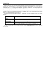
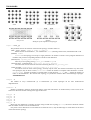
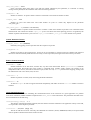
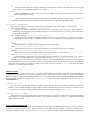
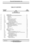
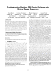
INSEE: User Manual
Javier Navaridas, Jose Miguel-Alonso, Jose Antonio Pascual, Francisco Javier Ridruejo
Department of Computer Architecture and Technology, The University of the Basque Country
INSEE, standing for Interconnection Networks Simulation and Evaluation Environment, is a lightweight framework to
perform functional simulation of interconnection networks, which means that the operation of the elements is part of the
simulation, but the actual machinery inside them is left apart. The low footprint of INSEE allows simulating large-scale
parallel system in a single off-the-shelf computer. For example, in previous research works we simulated networks with the
size of the largest BlueGene/L using a single commodity PC.
The quick speed of simulation allows to quickly estimating the performance of interconnected systems, but should not
be taken as a definitive result when it comes to build an actual system. In such case, a more detailed simulation that takes
into account all the hardware would be recommended.
In this document we present all knowledge required to employ INSEE. The manual will be organized as follows:
COMPILATION ..................................................................................................................................................... 2
PARAMETERS ...................................................................................................................................................... 3
TOPOLOGIES ........................................................................................................................................................ 3
ROUTER-LEVEL MECHANISMS ....................................................................................................................... 6
TRAFFIC GENERATION.................................................................................................................................... 10
OUTPUT ............................................................................................................................................................... 14
MISCELANEA ..................................................................................................................................................... 16
COMPILATION
INSEE is written in plain ANSI C, and therefore can be easily compiled for a wide variety of target architectures. In a
regular Linux box, the compilation instruction will be similar to the following:
cc -lm -O3 -o insee *.c
This instruction will generate an executable file whose name is insee. Reader should notice that the optimization switch (3)
is used for compilation. This is because simulation is boosted by some optimization made by the compiler. In our experimental
set-up, optimization options O2 and O3 show the best performance, without clear evidence of one being better than the other.
Still, the use of O3 is recommended.
There are some decisions that have to be made at compilation time. All of them are done by means of defines that can be
modified in constansts.h, or alternatively passed to the compiler (argument -D), which will override the definitions in such
file. The definitions are the following
PCOUNT
If not zero, routers keep count of the number of phits within and if there is no packet avoids wasting time in entering and
exiting the functions doing nothing. May boost simulations handling low loads, (for instance, traces that have large cpu
intervals, or low loads) but otherwise it is not likely to help. For this reason the default is 0
BIMODAL_SUPPORT
Deactivates (0) or activates (other value) the support for bimodal traffic. Note that bimodal traffic is experimental. Note
also that bimodal traffic requires some extra data structures that will increase the resources needed for simulation. For this
reason, if this feature is not going to be used it should be deactivated. This feature is deactivated by default.
TRACE_SUPPORT
If zero, deactivates support for the use of trace-driven simulation. Note that trace driven simulation requires of specific data
structures that will greatly increase the resources needed for simulation. For this reason, if trace-driven simulation is not going
to be used it should be deactivated. This is, therefore, the default option.
If one, activates support for trace-driven simulation and uses a single list to implement the occurred event list. This
implementation reduces memory footprint but at the cost of reducing performance.
If larger than one, activates support for trace-driven simulation and uses an array of lists to implement the occurred event
list. This implementation improves performance but at the cost of increasing memory footprint. Not recommended to simulate
large-scale systems.
EXECUTION_DRIVEN
If non-zero, INSEE performs an execution-driven simulation. Note that when it is activated Execution-driven simulation
will override any other traffic generation method stated in tpattern, for this reason, it is disabled by default.
PARAMETERS
INSEE accepts a wide variety of parameters to define the model of the different elements taking part into the simulation—
topology, router, workload—as well as the level of verbosity of the simulation. These parameters can be given by means of a
configuration file (fsin.conf) or alternatively as parameters when launching the application. Note that all parameters have
default values that will be overridden by those read from the configuration that, in turn, will be overridden by those parameters
given when launching the application. The correct formulation is the following:
parameter=value
In the configuration file, each parameter must be written in a single line. In the command line, each parameter have to be
separated by a space and if the arguments of the parameter are separated by means of space must be written between quotation
marks (“), for this reason underlines should be preferred.
The format conventions used in this user manual for the description of the valid parameters and their values are the
following:
"tpattern" : uniform
A valid parameter and its default value.
[trace]
Valid value of a parameter.
[distribute, rsdist]
A list of valid parameter values.
uniform|random
Alternative values with the same meaning (alias).
<nodes_x>
Some parameters require or just allow arguments. These should be separated
from the parameter that modify by means of spaces (‘ ’) or underlines (‘_’).
Note that those features that can not be considered stable are marked as EXPERIMENTAL. Most of them are part of our
current research.
TOPOLOGIES
mesh
torus
k-ary n-tree
twisted torus
thintree
Examples of the implemented topologies
midimew
indirect cube
"topo" : torus_4_4
This parameter allows the selection of the network topology. Possible values are:
[mesh, torus, ttorus] <nodes_x> <nodes_y> <nodes_z>
Meshes and tori are defined for 1, 2 or 3 dimensions. ttorus
(meaning twisted torus) is defined for 2D or 3D.
[midimew] <nodes>
midimew is a
2D topology but accepts a single parameter: the number of nodes. The topological definition of
midimew will put the corresponding number of nodes in each dimension.
[fattree|fat] <up/down_ports> <nstages>
The k-ary n-tree topology, being up/down_ports=k
and nstages=n.
[thintree|thin, slimtree|slim] <down_ports> <up_ports> <nstages>
Two narrowed versions of the fat tree with a narrowing factor of down_ports:up_ports.
[icube|tricube] <nodes/switch> <parallel_links> <n_x> <n_y> <n_z>
An indirect switch-to-switch cube topology, currently only for torus, but could be extended to any other cubelike topologies (may be done to ttorus). nodes/switch means the number of compute nodes attached to a switch.
parallel_links specifies the number of parallel links in each direction. n_x, n_y and n_z denote the number of
nodes in each dimension. We consider this topology a hybridization between direct and multistage topologies.
EXPERIMENTAL.
"nways" : 2
The number of ways: unidirectional (1) or bidirectional (2). Some topologies do not have unidirectional
implementation.
"faults" : 0
Number of randomly (uniform) located link failures. Note that link failures are unidirectional, so that a link can be
broken in a direction but still working in the opposite direction.
"sk_xy"
"sk_xz"
"sk_yx"
"sk_yz"
"sk_zx"
"sk_zy"
:
:
:
:
:
:
0
0
0
0
0
0
Skew from one dimension to another one when using twisted torus topology (ttorus). The skews should be smaller
than the number of nodes in the second dimension.
Only skews of two dimensions over the third one are allowed. This is, only the followings are valid values for the skews
of the twisted torus topology.
(sk_xy!=0 and sk_zy!=0)
(sk_xz!=0 and sk_yz!=0)
(sk_zx!=0 and sk_yx!=0)
Also if no skew is provided (i.e. all skews are 0) the program will switch automatically to the torus topology to perform
a faster simulation (because routing record calculation is faster).
ROUTER-LEVEL MECHANISMS
Model of the router
TRANSIT PORTS
"tql" : 4
Transit queue length, measured in packets.
"nchan" : 1
Number of Virtual Channels (hereafter VC) that share each physical channel. That is, the number of parallel queues in
each input port
INJECTION PORTS
"iql" : 8
Injection queue length, measured in packets.
"ninj" : 1
Number of injection queues in each injector. Some injection modes could override the selected value.
"par_inj" : 1 (YES)
Is parallel injection allowed? 0 means NO, any other means YES.
DEADLOCK AVOIDANCE MECHANISMS
"vc" : bubble
Virtual channel management strategy. Note that multistage and hybrid topologies have implicit their own VC
management. Also note that the available requesting policies (see parameter rmode) depend on this parameter. Possible
values are:
[bubble]
Bubble flow control to avoid deadlock using a single VC as the ESCAPE VC. Bubble mechanism restrict the
insertion of packets in an ESCAPE VC from any other channel (injection or transit), allowing them pass only if the
router has room in the input queue for at least bsize packets.
[double]
New strategies that use several bubble ESCAPE VCs with different DOR, in order to avoid deadlock and
improve performance while keeping VC management simple. EXPERIMENTAL.
[dally]
Dally’s strategies to avoid deadlock using two ESCAPE VCs to dissolve the cycles embedded in the rings of the
k-ary n-cubes.
[tree, icube]
Virtual channel management for indirect-cubes and trees. Note that these vc are not needed to be explicitly
defined. If these values are not consistent with the selected topology the program will switch to them. Trees can not
suffer of deadlock as they use shortest paths that do not create any cycle. Indirect cubes rely on bubble flow control
to avoid deadlock.
"bsize|bub" 2 (2_2_2)
The size of the bubble for each dimension. Up to three values can be specified, selecting the bubble size in each
dimension. If a value is not defined for a dimension it will take the value of the previous dimension. Minimum value for
bubble to work correctly is 2.
CROSSBAR POLICIES
"routing" : dim
The routing algorithm to use. It could be:
[dim, dir]
Dimension order routing (i.e. X+ X- Y+ Y- Z+ Z-) or Direction order routing (i.e. X+ Y+ Z+ X- Y- Z-). Used
only as oblivious routing in k-ary n-cubes. If one of these values is selected for a non-direct topology, the routing
algorithm will be switched to adaptive.
[static, adaptive]
Select between adaptive or static routing for multistage and hybrid networks. Adaptive routing select the
profitable port with more credits (i.e. more room). Static routing selects the same path for the same
source/destination pair.
"rmode" : oblivious
Policy to request output channels. Trees and indirect-cubes have their own request policy and do not need an explicit
Possible values are
rmode.
[random, shortest, smart, oblivious, bimodal]
Request policies in use with vc=bubble.
random request performs packet injection in a random VC. Packets try to continue in the same dim/way in an
adaptive VC, but if not possible, then jump to another adaptive VC at random. If no adaptive, profitable dim is
found, go to the ESCAPE VC.
In shortest request, packets try to continue in the same VC if they cannot, they try to go to the adaptive VC
with most space in its queue. If no adaptive, profitable dim is found, then go to ESCAPE VC. Injection is
considered a forced VC change, this is it will be done to the adaptive VC with more room or if not possible to the
ESCAPE VC.
If smart request is selected, packets are injected to a random channel and try to continue in the same dimension,
way and VC. If not possible, then jump to another, profitable dim, still using adaptive VCs. If no adaptive,
profitable dim is found, go to ESCAPE VC.
When using oblivious request there will be nchan parallel oblivious (DOR) VCs, once a packet has been
injected in a VC it will keep it.
bimodal request mode is used to generate and manage bimodal traffic(short messages: adaptive + long
messages: always ESCAPE to arrive destination in-order). EXPERIMENTAL.
[doubleob, doubleadap, hexaob, hexaadap]
Request policies available when vc=double.
In doubleob and doubleadap there are several ESCAPE VCs that follows each one a different oblivious DOR
(2D: XY, YX. 3D: XYZ, YZX, ZXY). In the former a VC is selected at random for each packet that will keep that
VC. In the latter once a VC is selected it is possible to change the VC (if bubble restriction is carried out).
hexaob and hexaadap are 3D versions in which the oblivious dor is not only increasing-order, but also reverseorder (i.e.: XYZ, YZX, ZXY, ZYX, YXZ, XYZ). All these modes are EXPERIMENTAL
[trc, basic, improved, adaptive]
Request policies for vc=dally management.
In trc all packets are injected in the same Escape channel. Packets remain in that channel, until reaching the
wrap-around link of a toroidal topology. Then, it is switched to the other one.
In basic those packets that have to cross the wrap-around links of a dimension—let us call them PW—circulate
through one Escape channel in that dimension. Those that do not have to use the wrap-around links—PD, standing
for direct packets—use the other Escape channel.
improved is an optimization of the basic policy to obtain better balancing in the utilization of both VCs. PW
packets are forced to transit by one of the Escape channels. PD packets choose randomly the Escape channel to use.
This way, PW packets cannot block PD packets, and thus PD packets eventually will use the other channel and
reach their destination. Note that this policy may lead to starvation of PW packets, as PD packets may make
intensive use of the two Escape channels.
adaptive is the same as the improved policy, adding routing adaptation capabilities. Two virtual channels work
as Escape channels following the improved policy and the remaining virtual channels are used as adaptive channels
(always using minimal paths). The packets randomly select a viable adaptive output port and, only in the case that
no adaptive channel is available, the packets try to use an Escape channel.
[tree, icube]
Request policies for all tree-like topology and for the indirect cube. Packets are injected in a random VC and
when in transit they will go to the profitable port with more room. Note that trees do not have an ESCAPE VC
notion due to there is impossible to deadlock the network. Also note that indirect cubes deadlock-avoidance rely on
bubble flow control.
"amode" : rr
Policy to arbitrate output ports. Note that output ports are arbitrated only if they are not in use by a packet, this is VCs
move a complete packet before re-arbitrate the output port. Allowed values are:
[rr]
Round robin arbitration.
[fifo]
Select the input port that requested the output first (FIFO).
[longest]
Select the input port having the highest queue occupation.
[random]
Select the input port randomly.
[oldest|age]
Select the input port containing the oldest packet (in terms of injection timestamp).
"cmode" : multiple
Consumption mode:
[multiple, single]
multiple consumption
allows the routers to deliver to the consumption port, in a single cycle, as many phits as
input ports, meaning that several packets arriving to destination can be consumed simultaneously. In single mode,
consumption port has to be arbitrated as any other port (using the required amode).
"imode" : shortest
Policy to select injection queues when several injection ports are available. This value can modify the selected value for
parameter "ninj". Valid values are:
[shortest]
Insert the packet in the queue with more room (no pre-routing). Multistage or hybrid topologies only are allowed
to use shortest, if other policy is selected the program will automatically set the injection policy to shortest. Note
that pre-routing does not make sense in such topologies as the first hop will always be from the NIC to the switch.
[dor, dsh, shp, lpath]
Perform pre-routing decision in order to select the target injection queue. These policies require a queue for each
available direction.
In dor each injection queue is dedicated for packets whose first hop is in that direction. Note that "dor" may be
dimension-order or direction-order, depending on parameter "routing". Note that most packet will be injected in
X+,Y+,Z+(routing=dir) or X+,X- (routing=dim).
dsh means dor + shortest. Tries to inject using dor policy, if the selected injection queue is full, use shortest
policy.
shp means shortest profitable, the packet will be injected in the valid queue (once pre-routed) that has the most
empty space.
lpath means longest path. Each packet will be injected in the queue associated to the direction with higher
number of hops.
PACKET ELIMINATION
Note that al packet elimination policies will be disabled when executing application traffic to ensure a proper operation of
these modes.
"extract" : 0 (NO)
Extract packets from the head of an injection queue to avoid Head-of-Line Blocking at injection. If its value is equal to
0 packet extraction is deactivated, otherwise it is activated. EXPERIMENTAL.
"drop_packets|drop" : 0 (NO)
Drop generated packets if the injection queue is full. Possible values are 0 meaning NO and any other value meaning
YES. EXPERIMENTAL.
CONGESTION CONTROL MECHANISMS
"global_cc" : 100.0 (DISABLED)
Global congestion control stops the injection of new packets when the network occupancy exceed global_cc% of the
network capacity. 100% means that global congestion control is disabled.
"update_period" : 0 (Always up to date)
The update period specifies how often the global occupation is computed and distributed. Note that for torus and mesh
the specified number is multiplied by the network diameter. 0 means that updated information is immediately available.
"bub_to_adap|lbr" : 0 (DISABLED)
Select the utilization of bubble flow control in the adaptive VC to provide congestion control. It allows to insert
(meaning that the packet comes from any different VC) a packet in a virtual channel only if the number of free packets in
the queue is bigger or equal to bub_to_adap.
"intransit_pr|ipr" : 0.0 (DISABLED)
In-transit priority congestion control: fraction of cycles to give priority to in-transit packets. 0 disables the congestion
control mechanism.
"timeout_upper_limit" : -1 (DISABLED)
When using adaptive congestion control, this is the threshold (to the number of cycles a packet stays in the router) to
enter in congested mode. EXPERIMENTAL
"timeout_lower_limit" : -1 (DISABLED)
When using adaptive congestion control, this is the threshold (to the number of cycles a packet stays in the router) to
abandon congested mode. EXPERIMENTAL
TRAFFIC GENERATION
DEFINITION OF TRAFFIC MODEL
"tpattern" : uniform
Traffic pattern to use during the simulation: select from the following:
[distribute, rsdist]
Distribution patterns, send packets consecutively to each destination. distribute starts sending to the next node
and rsdist to a random node.
[transpose, complement, butterfly, shuffle, reversal, tornado]
Permutation traffic. Each node sends messages to a destination node as defined by the permutation. Note that the
destination for each source is constant. Look at Dally’s book for a definition of the permutations.
[population|pop, histogram|hist]
Packets are generated following a probability distribution of distances, given as a population or a histogram. The
file containing the population or the histogram is determined by means of the parameter tracefile.
EXPERIMENTAL
[uniform|random, hotregion, hotspot, semi, local]
Random patterns.
uniform means uniform distribution of the traffic.
hotregion generates 25% of the traffic to 1/8 of the network and the remaining 75% uniformly along the whole
network (including the hot region).
hotspot generates 5% of the traffic to node 0 and the remaining 95% uniformly along the whole network. This
pattern may be excessively heavy for large-scale networks. EXPERIMENTAL
semi generates uniform traffic in the left half of the network (implemented only for direct topologies).
EXPERIMENTAL
local generates traffic with higher probability to be located in close proximity. This pattern is implemented for
k-ary n-cubes only. The exact definition is the following: EXPERIMENTAL
50% of the traffic goes to distance [0,1] (uniformly distributed).
25% goes to distance [2, 3].
12.5% goes to distance [4, 7].
The remaining 12.5% goes to distance 8 or further.
[trace]
Trace driven simulation. Causal relationship among packet receptions and sends is maintained. Note that to be
able to perform trace-driven simulation INSEE should be compiled with a TRACE_SUPPORT value other than 0.
"plength" : 16_4
Length of the packet measured in phits and length of the phit measured in bytes.
INDEPENDENT TRAFFIC SOURCES
"load" : 1.0
Injection load measured in phit/node/cycle.
"warm_up_period" : 25000
Number of cycles to run before starting the convergence checking phase.
"conv_period" : 1000
Period for stats capturing in order to assure the convergence of the system.
"conv_thres" : 0.05 (5%)
Threshold of the load to assure convergence. If during three consecutive periods the relations between the accepted
loads are within this threshold, the convergence phase ends and the simulator will start capturing results.
"max_conv_time" : 25000
If the convergence phase takes more cycles than the number indicated by this parameter, it is aborted. A warning
message will be printed, but the simulation will continue collecting statistics.
"nsamples" : 25
Number of “batches” to capture statistics. When in shot-mode it also means the number of shots.
"sample_size" : 2000
Number of cycles each batch lasts. The actual number of cycles in a batch may depend on the parameter
“min_batch_pkt”.
"min_batch_pkt" : 0 (constant time batches)
Minimum number of packets within each batch to consider it valid. If this number of packets is not reached the batch
measurements will continue for another sample_size cycles. This allows the batch capturing process to be guided by the
number of packets instead of the cycles if we set sample_size to 1 and min_batch_packet to the desired size in packets.
CAUSAL SYNTHETIC TRAFFIC
"trigger_rate" : 0.0 (DISABLED)
Probability of triggering a burst of packets after the reception of a packet.
"triggered" : 1
Number of packets in the triggered burst. Accepts up to two parameters in which an interval is defined. The length of
the burst is selected uniformly from that interval. If only a value is provided, the length of the burst if always the same.
BURSTY TRAFFIC SOURCES
"shotmode" : 0 (NO)
Should simulation run in shot mode, 0 means NO, any other value means YES. When tpattern is trace, shotmode
will be deactivated. Shot-mode (aka bursty traffic) is generated using synthetic traffic patterns, but instead of use
independent traffic sources, each node is allowed to inject, as fast as it can, shotsize packets before stopping, waiting until
all nodes finish. Then a new burst (shot) can start.
"shotsize" : 1
Number of packets in a burst (shot) when using shotmode simulation.
"numshots" : 25
An alias of nsamples in order to support backwards compatibility with older versions of fsin.conf. Number of shots to
simulate.
TRACE-DRIVEN SIMULATION
Trace driven-execution allows simulating the communication flow of the execution of a given application. To perform
trace-driven simulation, INSEE should be compiled with a TRACE_SUPPORT value other than 0. The parameters that affect tracedriven simulation are the following:
"background|bg_load|bg" : 0.0
The amount of background traffic (uniform) that will interfere with the simulation of an application. Likely to the load,
it is expressed in terms of phits/cycle/node.
"tracefile" : /dev/null (empty run)
The file to read the trace from. Currently, three different trace formats (ALOG, DIMEMAS, FSIN) are accepted. FSIN
itself is capable to determine the format of the trace file:
ALOG
This trace format shows the message interchanges of the nodes by means of the communication events (-101
send, -102 receive). Computation phases are not defined.
DIMEMAS
This is the DIMEMAS 2.0 trace format as defined by the BSC. Only point-to-point operations and CPU bursts
are understood and used by FSIN.
FSIN
This is a simple trace format specifically developed to feed FSIN. There are 3 types of event: ‘r’ receive, ‘s’
send and ‘c’ CPU. We can generate FSIN trace files from ALOG trace files with the alog2trc parser.
"placement" : row (row_0_0)
The placement strategy to put the trace’s tasks into the network nodes. The valid strategies are the following:
[consecutive, shuffle] <trace_nodes> <trace_instances>
Placement in indirect topologies, places the task into consecutive ports of the last stage switches or,
alternatively, one in each switch. The number of nodes in a trace and the number of concurrent copies of the traces
are accepted as parameters.
[row, column, quadrant] <trace_nodes> <trace_instances>
Placement in cube topologies, arranging the tasks consecutively in rows, columns or quadrants. The quadrant
strategy divide the network into 2ndim quadrants of half the size in each dimension, overriding the given parameters.
[random] <trace_nodes> <trace_instances>
Places the tasks in a random way, with a maximum of one task per node.
[shift] <shift> <trace_nodes> <trace_instances>
Places tasks consecutively (or in row order) but starting in the specified node given as a parameter.
[tricube] <pn_x> <pn_y> <pn_z> <trace_nodes> <trace_instances>
Places tasks in a tricube, arranging the nodes attached to each switch as a virtual mesh (pn_x × pn_y × pn_z).
[file] <placement_file> <trace_nodes> <trace_instances>
Tasks placement is defined in a file, whose name is given as a parameter. The format of the file is very simple, a
collection of 3-tuples each in a line. 3-tuples are defined as follows <node_id> <task_id > <instance_id >.
All of them accept 2 extra arguments: the number of nodes of the trace and the number of copies of the trace to place. If
these two parameters are not given explicitly to FSIN, it considers that the trace uses the whole network (i.e. the number of
tasks in the trace is equal to the number of nodes in the network). The only exception is quadrant placement that always
generates 2ndim instances of the read trace.
BIMODAL TRAFFIC
Bimodal traffic is composed of two types of messages, small messages composed by a single packet and long messages
composed by several packets. In this kind of execution packets that belong to small messages are routed using adaptive
routing,. Packets belonging to long messages, instead, are sent using static routes in such a way that they are delivered in-order.
Note that INSEE should be compiled with a BIMODAL_SUPPORT value other than 0 and that rmode must be bimodal.
EXPERIMENTAL
"longmessages" : 8
The size of the long messages measured in packets. These messages will only use Escape channels to arrive their
destination in order. Short messages are able to adapt to be delivered more quickly. This type of traffic is currently only for
torus, but may be extended to other topologies. Bimodal traffic will be generated only if rmode=bimodal.
"lng_msg_ratio" : 0.1 (10%)
The injection ratio of long message packets. Note that this relation is computed in a packet base, so the relation between
short messages and long messages would be smaller. This parameter should be in range [0 .. 1], otherwise the bimodal
traffic will be deactivated.
EXECUTION-DRIVEN SIMULATION
Execution-driven simulation (aka full system simulation) allows interfacing INSEE with a collection of running instances
of Simics in order to perform a more detailed simulation of the interconnection network. To perform execution-driven
simulation, INSEE should be compiled with a EXECUTION_DRIVEN value other than 0. Note that when INSEE is compiled to
support execution driven, the execution mode is execution being unable to switch to other traffic generation mode. The
parameters that affect execution-driven simulation are the following:
"fsin_cycle_relation" : 10
The number of cycles that FSIN is allowed to run during its time slice.
"simics_cycle_relation" : 100
The number of cycles that SIMICS instances are allowed to run during its time slice.
"serv_addr" : 8082
The UDP multicast port in use for this simulation.
"num_wait_periods" : 0
Interconnection delay that will be put at the destination host. It is measured in synchronization phases.
OUTPUT
INSEE can produce a wide variety of results captured during the simulation process. For the sake of simplicity, all the
statistics and information will be printed/stored in plain text CSV format, which is broadly recognized by mathematic and/or
analysis software. The only exception to this rule is the summary of simulation parameters that is printed in a compact format
to ease identifying simulations at a glance.
"plevel" : 0
The verbosity of the simulation results. The level of detail may slow down the simulation and noticeably increase the
memory requirements to perform simulation.
0: Just a final summary showing the execution time (both actual and simulated), the statistics captured during
simulation (look at bheaders) and a brief summary showing the parameters of the simulation.
1: Source/destination maps measured at injection and at consumption. Note that this output level will require a vast
amount of memory to store all the pair-to-pair communications. Note that memory requirements grow quadratically with
the number of nodes.
2: Port utilization map showing the average utilization of each port. This mode will significantly increase the amount
of memory needed to perform simulation. Memory requirements grow linearly with the number of nodes.
4: Distance histogram showing the distance distributions at injection and at consumption. Memory requirements are
barely affected.
8: Histogram of port utilization. This mode will significantly increase the amount of memory needed to perform
simulation. Memory requirements grow linearly with the number of nodes.
16: Packet-level traces. Too much verbose—should only be used for debugging purposes.
32: Phit-level traces. Too much verbose— should only be used for debugging purposes.
64: Evolution of the monitored node.
"pinterval" : 1000
Period to print partial results showing the evolution of the simulation.
"pheaders" : 2047 *all*
The information to show in each partial result printings. 0 means no partials. Otherwise, specify a bitmap:
1: clock.
2: injected load.
4: consumed load.
8: average delay.
16: deviation of delay.
32: maximum delay.
64: average injection delay.
128: deviation of injection delay.
256: maximum injection delay.
512: network occupancy.
1024: queue occupancy.
"bheaders" : 8191 *all*
Information showed when finalizing each batch. Also a bitmap:
1: time spent to finalize the batch.
2: average distance during this batch.
4: injected load.
8: consumed load.
16: packets sent.
32: packets received.
64: packets dropped.
128: average delay.
256: deviation of delay.
512: maximum delay.
1024:
maximum injection delay.
2048: network occupancy.
4096: queue occupancy.
"output" : fsin.#pid.out
A string with the prefix for the output files. If no name is given then the prefix will be set to "fsin.#pid.out", being
the system process identification of the program. This allows to have different runs with different output on the same
host, however when running on different hosts #pid could be repeated. Note that all the files are written in CSV format.
The appended suffixes (extensions) add by fsin are the following:
#pid
.mon
The file containing the evolution of the monitored node.
.map
The file containing the source/destination maps and/or the map of the channel utilization.
.hst
The file containing distance histograms and/or the histogram of channel utilization.
"monitored" : 1
The node to be monitored in the .mon file.
MISCELANEA
"rnds|rseed" 17
The random seed for the simulation. Note that there is just one random generator for the whole simulation. Random
numbers are used in traffic generation, routing, requesting, arbitrating and so on. It is possible to obtain different simulation
results by varying the seed.