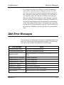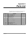
1
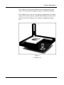
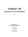
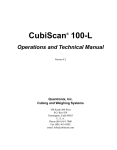
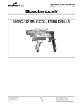
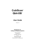
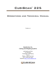
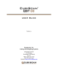
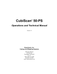
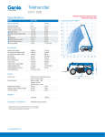
CubiScan 30
®
Operations and Technical Manual
Version 4.0
Quantronix, Inc.
Cubing and Weighing Systems
380 South 200 West
P.O. Box 929
Farmington, Utah 84025
U. S. A.
Phone (801) 451-7000
Fax (801) 451-0502
email: [email protected]
CubiScan 30 Operations and Technical Manual
CubiScan and the Quantronix logo are registered trademarks of Quantronix, Inc.
Scanning New Dimensions, Qbit, and The FreightWeigh System are trademarks of Quantronix, Inc.
Microsoft, Windows, Windows XP, Windows NT, Windows 2000 and their respective logos are registered trademarks of Microsoft Corporation in the United States and other countries.
All other brand and product names used in this manual are trademarks or registered trademarks of their respective companies.
CubiScan software and firmware are protected by international and domestic copyrights.
This document copyright © 2011 by Quantronix, Inc. All rights reserved.
No portion of this manual may be reproduced in any form without written permission from Quantronix, Inc.
Information in this manual is subject to change without notice.
Manual updated August 30, 2011.
The CubiScan 30 should only be serviced by qualified personnel.
CAUTION
Observe precautions for handling electrostatic sensitive devices when
setting up or operating the CubiScan 30.
WARNING
Disconnect all power to the CubiScan 30 before servicing or making
any connections.
The CubiScan 30 uses a laser diode that emits visible laser radiation.
AVOID DIRECT EYE EXPOSURE to the laser diode.
1 MILLIWATT MAXIMUM OUTPUT
670 nm WAVELENGTH
CLASS II LASER PRODUCT
Quantronix New Product Limited Warranty
Statement of Warranty. Subject and according to the Terms and Conditions set forth below, Quantronix, Inc.,
(hereafter referred to as “Quantronix”) warrants to the Buyer that its new product is in accordance with Quantronix’ published specifications (or those agreed upon with Buyer in writing) at the time of sale or lease and that
such product shall be free from defects in material and workmanship for a period of one year from, as applicable: the date of sale or the Commencement Date under a written equipment lease or rental agreement (the “Warranty Period”). For purposes of this warranty, the term “Buyer” shall mean and refer only to the party which
originally—whether from Quantronix directly, or from a distributor, agent, or reseller authorized by Quantronix
—purchases, or leases under a written equipment lease or rental agreement, the Quantronix product which is the
subject of this warranty.
Terms and Conditions of Warranty. This warranty is applicable exclusively to original equipment products,
and components which were manufactured by Quantronix. Quantronix does not warrant, for any purpose, any
part or component manufactured by another manufacturer, nor which is used or rebuilt. Quantronix’ obligation
and liability under this warranty is expressly limited to repair or replacement (at its option) of the warranted
equipment or components within the Warranty Period. A purchase by a Buyer of equipment which it had first
leased or rented shall not start a new Warranty Period.
In the event of the occurrence of a claim under this warranty, the Buyer shall have a duty to promptly notify
Quantronix in writing of the nature and specifics of the claimed defect. Failure to so notify shall void this warranty. Any claim of a warranted defect is subject to inspection and analysis by Quantronix to conclusively identify or confirm the nature and cause of failure and application of this warranty. Any defective components,
mechanical or electrical, will be repaired or replaced, at the discretion and authorization of Quantronix, at Quantronix’ facilities in Utah. It shall be the Buyer’s responsibility to return the faulty equipment or components to
Quantronix at Buyer’s expense. Quantronix’ obligation shall not include transportation charges, nor labor, material, or service charges involved in the removal, return, or installation of equipment or components.
Except as provided herein, Quantronix shall have no other obligation or liability due to defective equipment or
components. Accordingly, but without limitation, Quantronix shall not be liable for: losses, injury, or damage
caused to persons or property by Quantronix products or their failure; indirect, special or consequential damages
of any nature including but not limited to loss of profit, delays, or expenses, such as those arising from the use of
or inability to use the products; nor any incidence of personal injury or property damage arising from the negligence or willful act of anyone other than itself or its employees.
Quantronix reserves the right to incorporate improvements in material and design of its products without notice
and is not obligated to incorporate the same improvements in equipment previously manufactured.
Conditions Which Void Warranty. This agreement shall not apply to equipment or components which
has/have:
A.
B.
C.
Been the subject of repairs or modifications not authorized by Quantronix.
Not been operated under normal use and service according to that for which it was intended.
Not been operated or maintained in accordance with Quantronix’ printed instructions.
Quantronix New Product Limited Warranty (continued)
D.
E.
F.
G.
Been subject to misuse, negligent handling, improper installation, accident, damage by fire, submersion, or
act of God.
Had serial numbers altered, defaced, or removed.
Been sold, loaned, leased, subleased, or in any other way transferred to or placed within the control of any
party other than the Buyer.
Been operated beyond capacity.
THE FOREGOING IS IN LIEU OF ALL OTHER REMEDIES, GUARANTEES, LIABILITIES, OR WARRANTIES. QUANTRONIX MAKES NO OTHER WARRANTY, EXPRESS OR IMPLIED, AND MAKES NO
WARRANTY OF MERCHANTABILITY OR FITNESS FOR ANY PARTICULAR PURPOSE. This statement
sets forth the full extent of Quantronix’ liability for breach of any warranty or deficiency in connection with the
sale or use of the product. No employee or representative of Quantronix is authorized to change this warranty in
any way or grant any other warranty.
Table of Contents
Chapter 1
Product Description . . . . . . . . . . . . . . . . . . . . . . . . . . . . . . . . . . . . . . 1
Accessories . . . . . . . . . . . . . . . . . . . . . . . . . . . . . . . . . . . . . . . . . . . . . . . . . 2
Specifications . . . . . . . . . . . . . . . . . . . . . . . . . . . . . . . . . . . . . . . . . . . . . . . 3
Chapter 2
Setup. . . . . . . . . . . . . . . . . . . . . . . . . . . . . . . . . . . . . . . . . . . . . . . . . . . . . 7
Unpacking . . . . . . . . . . . . . . . . . . . . . . . . . . . . . . . . . . . . . . . . . . . . . . . . . . 8
Placement . . . . . . . . . . . . . . . . . . . . . . . . . . . . . . . . . . . . . . . . . . . . . . . . . 10
Attaching the Height Caliper Tower . . . . . . . . . . . . . . . . . . . . . . . . . . . . . 11
Connecting the Scale Display . . . . . . . . . . . . . . . . . . . . . . . . . . . . . . . . . . 12
Connecting the Serial Cable . . . . . . . . . . . . . . . . . . . . . . . . . . . . . . . . . . . 13
Extending the Legs and Leveling . . . . . . . . . . . . . . . . . . . . . . . . . . . . . . . 13
Removing the Laser Sensor Dust Cover . . . . . . . . . . . . . . . . . . . . . . . . . . 14
Connecting the Optional Caliper. . . . . . . . . . . . . . . . . . . . . . . . . . . . . . . . 15
Connecting Power . . . . . . . . . . . . . . . . . . . . . . . . . . . . . . . . . . . . . . . . . . . 16
Connecting the Optional Battery Pack . . . . . . . . . . . . . . . . . . . . . . . . 17
Installing the Qbit Software . . . . . . . . . . . . . . . . . . . . . . . . . . . . . . . . . . . 17
Setup Checklist . . . . . . . . . . . . . . . . . . . . . . . . . . . . . . . . . . . . . . . . . . . . . 18
Chapter 3
Operation . . . . . . . . . . . . . . . . . . . . . . . . . . . . . . . . . . . . . . . . . . . . . . . 19
Before You Begin . . . . . . . . . . . . . . . . . . . . . . . . . . . . . . . . . . . . . . . . . . . 19
Cubing and Weighing Objects . . . . . . . . . . . . . . . . . . . . . . . . . . . . . . . . . 19
Using the Scale Display . . . . . . . . . . . . . . . . . . . . . . . . . . . . . . . . . . . 20
Measuring Cube-Like Objects . . . . . . . . . . . . . . . . . . . . . . . . . . . . . . 20
Measuring Short or Light Objects . . . . . . . . . . . . . . . . . . . . . . . . . . . 21
Measuring Irregular Shapes Using CubiCorners . . . . . . . . . . . . . . . . 22
CubiCorners Tare Values. . . . . . . . . . . . . . . . . . . . . . . . . . . . . . . 23
Using CubiCorners. . . . . . . . . . . . . . . . . . . . . . . . . . . . . . . . . . . . 23
Measuring Irregular Shapes Using the Optional Caliper . . . . . . . . . . 24
CubiScan 30
i
Table of Contents
Chapter 4
Calibration . . . . . . . . . . . . . . . . . . . . . . . . . . . . . . . . . . . . . . . . . . . . . .27
Zeroing the CubiScan . . . . . . . . . . . . . . . . . . . . . . . . . . . . . . . . . . . . . . . .27
Using Test Mode . . . . . . . . . . . . . . . . . . . . . . . . . . . . . . . . . . . . . . . . . . . .28
Calibrating the CubiScan 30 . . . . . . . . . . . . . . . . . . . . . . . . . . . . . . . . . . .29
Calibrating the Sensors . . . . . . . . . . . . . . . . . . . . . . . . . . . . . . . . . . . .29
Calibrating the Scale . . . . . . . . . . . . . . . . . . . . . . . . . . . . . . . . . . . . . .30
CubiScan 30 with serial numbers below 2500 . . . . . . . . . . . . . . .30
CubiScan 30 with serial numbers 2500 and above. . . . . . . . . . . .32
Chapter 5
Maintenance . . . . . . . . . . . . . . . . . . . . . . . . . . . . . . . . . . . . . . . . . . . . .35
Precautions. . . . . . . . . . . . . . . . . . . . . . . . . . . . . . . . . . . . . . . . . . . . . . . . .35
Cleaning the Laser Sensor . . . . . . . . . . . . . . . . . . . . . . . . . . . . . . . . . . . . .36
Replacing the Reflector Cover Strips . . . . . . . . . . . . . . . . . . . . . . . . . . . .36
Chapter 6
Troubleshooting . . . . . . . . . . . . . . . . . . . . . . . . . . . . . . . . . . . . . . . . .39
Nothing Happens When You Turn Power On . . . . . . . . . . . . . . . . . . . . . .40
Readings Are Not Accurate . . . . . . . . . . . . . . . . . . . . . . . . . . . . . . . . . . . .40
Qbit Error Messages . . . . . . . . . . . . . . . . . . . . . . . . . . . . . . . . . . . . . . . . .41
Appendix A Parts List . . . . . . . . . . . . . . . . . . . . . . . . . . . . . . . . . . . . . . . . . . . . . . . .43
ii
CubiScan 30
Table of Illustrations
Figure 1
Figure 2
Figure 3
Figure 4
Figure 5
Figure 6
Figure 7
CubiScan 30. . . . . . . . . . . . . . . . . . . . . . . . . . . . . . . . . . . . . . . . . . . . . . . . . . . . 2
CubiScan 30 Accessories. . . . . . . . . . . . . . . . . . . . . . . . . . . . . . . . . . . . . . . . . . 9
Attaching the Height Caliper Tower . . . . . . . . . . . . . . . . . . . . . . . . . . . . . . . . 12
CubiScan 30 Connectors . . . . . . . . . . . . . . . . . . . . . . . . . . . . . . . . . . . . . . . . . 13
Removing the Dust Cover . . . . . . . . . . . . . . . . . . . . . . . . . . . . . . . . . . . . . . . . 15
Optional Caliper . . . . . . . . . . . . . . . . . . . . . . . . . . . . . . . . . . . . . . . . . . . . . . . 16
Using CubiCorners . . . . . . . . . . . . . . . . . . . . . . . . . . . . . . . . . . . . . . . . . . . . . 24
CubiScan 30
iii
Table of Illustrations
Notes
iv
CubiScan 30
Chapter 1
Product Description
The CubiScan® 30 is a precision volume measuring and weighing
instrument for applications where precise weighing and measuring
is required. The CubiScan 30 is ideally suited for weighing and
measuring applications involving publication media such as books,
cassette tapes, and compact discs.
The CubiScan 30 design is unique because it combines high accuracy dimensional measuring and weighing into one operation. The
unit interfaces with a standard PC computer via a serial port. The
data are collected into a convenient database format and may be
transmitted to another host system if desired.
An object to be measured is placed on the measurement platform.
Length and width measurements are determined by a proprietary
laser diode optical sensor. The height measurement is recorded by a
precision contacting linear caliper. The object is simultaneously
weighed by a precision load cell beneath the measurement platform.
Electronics in the base of the CubiScan 30 process the data and
transmit it to the PC computer for further processing, storage, and
display.
Quantronix’ proprietary Qbit™ software application (provided on
CD-ROM) is used to operate the CubiScan 30 from a connected
computer.
The CubiScan 30 uses an external AC adapter, but a battery pack is
available if you want the CubiScan 30 to be portable (operated with
a laptop computer).
CubiScan 30
1
Product Description
The CubiScan 30 has been designed for use in industrial environments. The frame and housings are made of machined aluminum.
The CubiScan 30 is easy to set up, operate, and maintain. Its simple
design and extreme accuracy coupled with intelligent circuitry and
software make the CubiScan 30 a valuable weighing/measuring
tool.
Figure 1
CubiScan 30
2
CubiScan 30
Product Description
Accessories
Accessories
The following accessories are available for the CubiScan 30:
• Battery pack—holds four “AA” batteries and will operate the
CubiScan for 6 to 8 hours. The battery pack connects to the
POWER connector on the back panel of the CubiScan 30.
• Caliper—used to measure an object's dimensions manually. The
measurement data is sent directly to the computer. Various caliper sizes are available.
Specifications
Electrical
Voltage:
W
(AC power adapter) 117 VAC, 60 Hz, 5
or 230 VAC, 50 Hz (European units)
Battery option:
current
(4 “AA” batteries) 150 mA maximum
draw @ 12 – 18 VDC (6-8 hours opera-
tion)
Laser Specifications
CubiScan 30
Type:
Visible laser diode
Power output:
1.0 mW maximum
Wave length:
670 nm
Classification:
Class II Laser Product
3
Specifications
Product Description
Measuring Capacities
Minimum Object Dimensions:
1.0 x 1.0 x 0.005 in (2.5 x 2.5 x 0.01 cm) with CubiCorners
1.0 x 1.0 x 0.20 in (2.5 x 2.5 x 0.51 cm) without CubiCorners
Maximum Object Dimensions:
15 x 15 x 4 in (38 x 38 x 10 cm)
Dimension Increment:
Length and width:
Height:
0.02 in (0.05 cm)
0.005 in (0.01 cm)
Maximum Object Weight:
Serial nos. below 2500: 10 lbs (5 kg)
Serial nos. above 2500: 15 lbs (7 kg)
Weight Increment:
0.005 lbs (0.002 kg)
Environmental
Operating Temperature:
40° to 104° F (5° to 40° C)
Humidity:
0 to 90% non-condensing
Physical
4
Total Footprint Required:
17.5 x 17.5 in (44 x 44 cm)
Height:
12 in (30 cm)
Shipping Weight:
42 lb (18.9 kg)
Net Weight:
24 lb (11 kg)
Shipping Dimensions:
23 x 21 x 10 in (58 x 53 x 25 cm)
CubiScan 30
Product Description
Specifications
Outputs
(1) EIA RS-232-C serial communications port
Load Cell
Forged and machined aluminum
Single point 350 Ohm strain gage
10 lb (5 kg) net capacity standard (serial numbers below 2500)
15 lb (7 kg) net capacity standard (serial numbers above 2500)
CubiScan 30
5
Specifications
Product Description
Notes
6
CubiScan 30
Chapter 2
Setup
The CubiScan 30 measurement platform is shipped as an assembled
unit with the exception of the height caliper tower, which is easily
installed. This chapter provides instruction for assembling and setting up the CubiScan 30 and your computer, as follows. All steps
should be performed in the order they appear.
• Unpacking the CubiScan
• Placement of the CubiScan
• Attaching the height caliper tower
• Connecting the scale display to the CubiScan
• Connecting the serial cable
• Extending the legs and leveling the CubiScan
• Removing the laser sensor dust cover
• Connecting power to the CubiScan
• Installing the Qbit software application
CubiScan 30
7
Unpacking
Setup
Unpacking
The CubiScan 30 is shipped in a custom-fitted container lined with
foam inserts to protect the instrument and accessories during shipping and storage.
Do the following to unpack the CubiScan.
1. Open the shipping container.
2. Remove the height caliper tower and AC power adapter from
the foam insert and set them on a clean surface, then remove the
foam insert from the container.
3. Grasp the CubiScan 30 platform by the sides and carefully pull
upward. DO NOT LIFT BY THE PLEXIGLASS LASER
HOUSING. The platform should easily slide out of the protective foam.
4. Place the platform on a stable, level surface.
Accessories are stored in side compartments of the shipping
container. Carefully remove the contents of each compartment
and place them on a clean surface for examination prior to
instrument assembly.
Examine the shipping container interior for any loose accessories, then replace the foam inserts and refasten the container lid.
Retain the container for future shipping or storage
8
CubiScan 30
Setup
Unpacking
Figure 2
CubiScan 30 Accessories
Examine the accessories included in the shipping container and verify that you have the following items:
❒ Remote scale display and cable
❒ AC power adapter (110 or 220 VAC)
❒ Round bubble level
❒
5
/64" Allen wrench
❒ (4) SFHCS machine screws
❒ RJ-11 communications cable
❒ RJ-11 to DB9 adapter
❒ RJ-11 to DB25 adapter
❒ (3) CubiCorners
CubiScan 30
9
Placement
Setup
❒ Dust cover
❒ (2) spare reflector cover strips
❒ 8" x 8" x 1/4" (20.32 x 20.32 x .635 cm) calibration standard box
❒ Operations and Technical Manual
❒ Qbit software application CD-ROM
If optional accessories were ordered (caliper or battery pack), also
verify that they were received.
If any of the accessories are missing or defective, contact Quantronix or your system integrator.
NOTE ☞
A power strip (not included) is recommended for turning the CubiScan power off and on.
Placement
The CubiScan 30 is designed to be operated in a warehouse environment; however, for proper operation the following conditions should
be met if possible.
❒ The CubiScan should not be subjected to extremes in temperature or humidity. Locate the CubiScan as far from open freight
doors as possible. Heaters or air conditioners should not blow
directly on the CubiScan.
❒ Protect the CubiScan from static electricity.
❒ The CubiScan and the computer should be placed on a flat,
sturdy surface as free from vibration as possible. Excess vibration can reduce the accuracy of the CubiScan 30.
10
CubiScan 30
Setup
Attaching the Height Caliper Tower
❒ The CubiScan's measurement platform is free-floating. Nothing
should be resting against or sitting on the measurement platform.
❒ The computer should be as close to the CubiScan as possible.
The operator needs to use the keyboard on the computer while
cubing and weighing objects using the CubiScan 30.
❒ Orient the CubiScan so that the operator has easy access to the
top of the measurement platform.
Attaching the Height Caliper Tower
Attach the height caliper tower to the left corner of the measurement
platform using the four socket, flat-head machine screws included
with the CubiScan 30 accessories, as follows.
1. Place the tower against the back corner of the measurement
platform on the outside. The plastic caliper head should rest
against the platform surface.
2. Align the four screw holes in the tower with the holes on the
back corner of the measurement platform and attach the
machine screws using the 5/64" Allen wrench, as shown on the
next page. Retain the Allen wrench for future disassembly.
CubiScan 30
11
Connecting the Scale Display
Setup
Figure 3
Attaching the Height Caliper Tower
3. Connect the 1/8" jack to the connector located on the back of the
CubiScan base. Make certain that the connector is fully seated.
Connecting the Scale Display
Connect the remote scale display module to the 8-pin, RJ-45 connector labeled “SCALE” on the back of the CubiScan base. Refer to
Figure 4 on the next page for the connector location. Be sure that the
plug is fully seated in the socket.
12
CubiScan 30
Setup
Connecting the Serial Cable
Connecting the Serial Cable
A communication serial cable is used to connect the computer to the
CubiScan 30. The supplied serial cable has a 6-pin, RJ-11 connector
at each end. This cable allows the CubiScan 30 to communicate
weight information from the scale to the computer.
Plug one of the 6-pin connectors into the socket labeled “OUTPUT”
on the back of the CubiScan base (refer to the figure below).
Figure 4
CubiScan 30 Connectors
Connect either a DB9 or DB25 adapter (to match your computer's
serial port connector) to the other end of the serial cable, and then
connect it to an available serial (COM) port on the computer.
Extending the Legs and Leveling
Before operating the CubiScan 30, extend the leveling legs and level
the CubiScan base. With the CubiScan 30 placed in an appropriate
location (as outlined in the “Placement” section), take the following
steps.
1. Lift or tilt the CubiScan base, and locate the four leveling legs
under the corners.
2. Turn each leg until it is fully extended to allow adequate space
for the attached cables under the base.
CubiScan 30
13
Removing the Laser Sensor Dust Cover
Setup
3. Set the base on its legs on a flat surface, and place the round
bubble level (included with the CubiScan) on the measurement
platform.
4. Look at the leveling bubble and determine if the CubiScan is
level.
5. If the base is not level, adjust the legs until the bubble is centered within the center circle of the level. Maintain as much
cable clearance as possible under the base of the CubiScan.
6. When the leveling bubble is centered, verify that all four of the
CubiScan's legs are resting against the supporting surface. The
CubiScan should not rock or tilt when light pressure is applied
at any location on the measurement platform.
NOTE ☞
Verify that all cables are routed so they do not touch the sides of the
scale housing or the measurement platform. Twisted or tight cables
can push against the housing or the platform causing inaccurate
weight measurements.
Removing the Laser Sensor Dust Cover
The laser sensor is located on the front corner of the measurement
platform and is encased in a cylinder of clear acrylic plastic for protection. When shipped, a clear plastic dust cover was taped in front
of the laser sensor to protect it during shipping.
The dust cover must be removed before operating the CubiScan
30.
To remove the dust cover, simply peel off the tape and lift the cover
off the platform (see the figure on the next page).
Retain the cover to be used if the CubiScan is shipped or stored.
14
CubiScan 30
Setup
Connecting the Optional Caliper
Figure 5
Removing the Dust Cover
Connecting the Optional Caliper
If you purchased the optional caliper (used to measure an object's
dimensions manually), do the following to connect the caliper to the
CubiScan 30.
1. Refer to the documentation supplied with the caliper to identify
the following components:
•
•
•
•
•
•
CubiScan 30
Power on/off switch
Zero switch
In/mm switch
Data switch
Lock
Battery compartment
15
Connecting Power
Setup
Figure 6
Optional Caliper
2. Unwrap the cable attached to the caliper.
3. Turn the plug on the cable so the key is at the bottom, and then
connect it to the socket labeled “CALIPER” on the back panel
of the CubiScan. Refer to Figure 4 on page 13.
Connecting Power
The CubiScan 30 is powered by an external AC power adapter. Take
the following steps to connect power to the CubiScan.
1. Connect the 3-pin DIN connector on the AC power adapter to
the “POWER” connector on the back of the CubiScan base.
2. Plug the AC power adapter into a wall outlet or power strip
equipped with an ON/OFF switch.
If you use a power strip, you can connect the computer to the
same power strip so that they will both be powered on at the
same time.
16
CubiScan 30
Setup
Installing the Qbit Software
The back panel “PWR” LED will light when power is connected.
NOTE ☞
The CubiScan should be powered on before running the Qbit operating software.
Connecting the Optional Battery Pack
If you purchased the optional battery pack, take the following steps
to connect it to the CubiScan.
1. Connect the 3-pin DIN connector on the battery pack to the connector labeled “POWER” on the back of the CubiScan base.
2. Turn the battery pack on.
The back panel “PWR” LED will light when power is connected.
Installing the Qbit Software
A CD-ROM is provided containing the Qbit software that is used to
operate the CubiScan 30.
Follow the instructions in the CubiScan Qbit User Guide, located on
the CD-ROM, to install and use Qbit. You can also download the
user guide from the Quantronix Web site at www.cubiscan.com.
CubiScan 30
17
Setup Checklist
Setup
Setup Checklist
Before using the CubiScan 30 for the first time, verify the following.
❒ Have the CubiScan 30 and the computer been placed in the
proper operating environment? (page 10)
❒ Has the height caliper tower been installed? (page 11)
❒ Has the scale display been connected to the CubiScan?
(page 12)
❒ Has the serial communications cable been connected to a serial
(COM) port on the computer and to the CubiScan? (page 13)
❒ Have the leveling legs been extended fully and the base of the
CubiScan leveled? (page 13)
❒ Is the CubiScan measurement platform free moving? No object,
cable or cord, etc., should be resting on or against the measurement platform.
❒ Has the AC power adapter been connected to the CubiScan and
plugged in? (page 16)
❒ Has the Qbit software been installed on your computer?
(page 17)
18
CubiScan 30
Chapter 3
Operation
This chapter provides instructions for operating the CubiScan 30.
NOTE ☞
The platform of the CubiScan should be kept clean and free of all
objects that are not being measured.
Before You Begin
To turn on the CubiScan and start the Qbit software program, take
the following steps.
1. Make sure there are no objects on the CubiScan platform.
2. Turn on the CubiScan 30. Do not touch the CubiScan platform during startup.
3. Turn on the computer, and start Qbit. Refer to the CubiScan
Qbit User Guide for instructions.
Cubing and Weighing Objects
Refer to the CubiScan Qbit User Guide for instructions on cubing
and weighing using Qbit.
CubiScan 30
19
Cubing and Weighing Objects
Operation
The CubiScan 30 has been designed to measure objects with maximum dimensions of 15" long by 15" wide by 4" high (38 x 38 x 10
cm) and a maximum weight of 10 lbs (5 kg) for CubiScans with
serial numbers below 2500 or 15 lbs (7 kg) for CubiScans with
serial numbers above 2500.
While the CubiScan has overload protection, objects heavier than
10 lbs (5 kg) for CubiScans with serial numbers below 2500 or 15
CAUTION lbs (7 kg) for CubiScans with serial numbers above 2500 should
not be placed on the platform. Overloading the scale or shock
loading (dropping a heavy object on the scale) can cause
permanent zero shift, making the scale inoperable.
Using the Scale Display
When you cube and weigh an object on the CubiScan 30, in addition
to the dimensions and weight in Qbit, the object’s weight is displayed on the remote scale display connected to the CubiScan.
Refer to “Connecting the Scale Display” on page 12 for instructions
to connect the scale display to the CubiScan.
The scale display also has buttons for zeroing and testing the scale.
Refer to “Zeroing the CubiScan” on page 27.
Measuring Cube-Like Objects
Take the following steps to measure cube-like objects.
1. Place the object to be cubed and weighed on the platform with
the ID number or barcode on top or visible.
NOTE ☞
20
Do not lean on or touch the CubiScan platform or the object while it
is being cubed and weighed. Any kind of contact with the platform
during the measurement process can alter the weight or sensor
reading or give you an error message.
CubiScan 30
Operation
Cubing and Weighing Objects
2. Carefully lift the height caliper using the knob at the top of the
rod, and slide the object against the back corner until it is in
contact with both side panels.
3. Lower or drop the height caliper onto the object.
4. Identify and measure the object using Qbit. Refer to the CubiScan Qbit User Guide for instructions.
NOTE ☞
If you suspect that a height or weight measurement is inaccurate,
zero the CubiScan (refer to “Zeroing the CubiScan” on page 27 for
instructions). If the length or width measurements appear to be
inaccurate, you may need to calibrate the CubiScan (refer to “Calibration” on page 27).
Measuring Short or Light Objects
Objects that are shorter than the height specification or lighter than
the weight specification (shown below), such as thin pamphlets or
single sheets of paper, can be measured using the Stacked Quantities
function in Qbit. The weight and height values of the objects being
measured are divided by the quantity specified to obtain the net
weight and height of a single object.
Height: less than 0.20 in. or 0.51 cm (less than 1/4 inch)
Weight: 0.005 lb or 4 grams (approximately 11/2 sheets of
8 1/2 x 11 inch paper)
NOTE ☞
When measuring single sheets of paper, height is more of a limitation than weight. Paper sheets need to be measured in stacks greater
than the height specification stated above.
Do the following to determine the measurements of a short or light
object.
CubiScan 30
21
Cubing and Weighing Objects
Operation
1. Place the stack of objects on the platform. Make sure the edges
are aligned. If some sheets of paper are curled, for example, you
may want to use the CubiCorners (refer to “Measuring Irregular
Shapes Using CubiCorners” on page 22).
2. Carefully lift the height caliper using the knob at the top of the
rod, and slide the stack against the back corner until it is in contact with both side panels. Make certain that the edges are still
aligned.
3. Lower the height caliper onto the stack of objects.
4. Identify and measure the stacked objects, and enter the quantity
in the Stacked Quantity box in Qbit. Refer to the CubiScan Qbit
User Guide for instructions.
Measuring Irregular Shapes Using CubiCorners
Using CubiCorners (included with the CubiScan 30) improves the
accuracy of cubing objects that are irregular in shape or have
rounded edges, for example, books with spiral or irregular spines.
CubiCorners help the laser sensor more clearly identify the length
and width of odd-shaped objects. You should use CubiCorners if
any of the following are true:
• The length and/or width of the object are irregular.
• The height of the object is less than 0.20 in. or 0.51 cm (less than
1
/4 inch)
CubiCorners are provided in sets of three. You should generally use
all three CubiCorners to maintain even edges. Each corner has the
same dimensions and weight.
22
CubiScan 30
Operation
Cubing and Weighing Objects
CubiCorners Tare Values
To obtain accurate measurements and weight when using CubiCorners, you need to enable the tare option and enter tare values in Qbit
so that the CubiCorners' dimensions and weight are automatically
subtracted from the measurements of an object. Refer to the CubiScan Qbit User Guide for instructions.
Enter the following tare values in Qbit’s options:
Length:
Width:
Height:
Weight:
0.08 in (0.20 mm)
0.08 in (0.20 mm)
0.038 in (0.10 mm)
0.013 lbs (0.005 kg)
0.08 inches is the thickness of the plastic in each CubiCorner. 0.013
pounds is the total weight of all three CubiCorners.
Using CubiCorners
Do the following to measure irregular objects using CubiCorners.
1. Make sure tare is enabled and the tare values shown above are
entered in Qbit. Refer to the CubiScan Qbit User Guide for
instructions.
2. Place the object on the CubiScan platform with the ID number
or bar code on top or visible.
3. Position the CubiCorners with the solid surface of each corner
on the BOTTOM, as shown in the figure on the next page. The
sides of each CubiCorner should fit snugly against the object,
with no visible gap.
CubiScan 30
23
Cubing and Weighing Objects
Operation
Figure 7
Using CubiCorners
4. Carefully lift the height caliper using the knob at the top of the
rod, and slide the object against the back corner until it is in
contact with both side panels. If necessary, reposition the CubiCorners.
5. Lower the height caliper onto the object.
6. Identify and measure the object and apply the tare values using
Qbit. Refer to the CubiScan Qbit User Guide for instructions.
Measuring Irregular Shapes Using the Optional
Caliper
The CubiScan 30’s optional caliper can be used to measure objects
with one or more irregular or “non-cubelike” dimensions. You can
enter one or more dimensions measured manually with the caliper in
Qbit.
24
CubiScan 30
Operation
Cubing and Weighing Objects
Refer to the data sheet with the caliper to identify components and
features of the caliper.
Take the following steps to manually measure all three dimensions
of an object.
1. Place the object on the center of the Cubiscan platform.
2. Close the caliper all the way and then turn the on/off switch to
ON (this is necessary to “zero” the caliper). When turned on,
the display shows the current measurement.
3. Verify that the IN/MM (inches/millimeters) setting is correct.
The display shows “in” or “mm” to the right of the measurement. (This setting applies to the caliper display only. The Qbit
software uses its own settings.)
4. Identify the object in Qbit. Refer to the CubiScan Qbit User
Guide for instructions.
5. Use the thumb roller on the caliper to adjust the opening and
measure the object's length.
6. In Qbit, pull down the Caliper menu, and select Length.
7. Within 30 seconds, press the DATA key on the caliper to record
the length measurement in Qbit.
8. Measure the width with the caliper.
9. Pull down the Caliper menu in Qbit, and select Width.
10. Within 30 seconds, press the DATA key on the caliper to record
the width measurement in Qbit.
11. Measure the height with the caliper.
12. Pull down the Caliper menu in Qbit, and select Height.
CubiScan 30
25
Cubing and Weighing Objects
Operation
13. Within 30 seconds, press the DATA key on the caliper to record
the height measurement in Qbit.
14. When you are finished with the caliper, turn the on/off switch to
OFF to conserve the battery.
26
CubiScan 30
Chapter 4
Calibration
The CubiScan 30 was calibrated at the factory. The CubiScan may
need to be recalibrated if it is subjected to any type of mechanical
shock or rough handling. The Qbit program has the following functions used to reset, test, and recalibrate the CubiScan 30:
• If you suspect any problem with height or weight measurement
accuracy, zero the CubiScan. Use the Zero function in Qbit to
reset the dimensions to zero. Use the remote scale display to zero
the weight. Refer to “Zeroing the CubiScan” below.
• Use the Test Mode function in Qbit to test the CubiScan for measurement accuracy. The Test Mode places the CubiScan in a continuous measure mode for test purposes. Refer to “Using Test
Mode” on page 28.
• Use the Calibrate function in Qbit to calibrate the length, width,
and height sensors. Use the TEST button on the scale display to
calibrate the CubiScan scale. Refer to “Calibrating the CubiScan
30” on page 29.
Zeroing the CubiScan
Zeroing the CubiScan sets the dimension and weight measurements
to zero when the platform and scale are empty. You may need to
zero the CubiScan in the following circumstances.
CubiScan 30
27
Using Test Mode
Calibration
• If, during a long measuring session, environmental conditions
(temperature and humidity) have changed noticeably.
• If you suspect that the last zeroing was in error (e.g., something
was on the platform).
NOTE ☞
Zero the Sensors
Zero the Scale
Make certain that the platform is free of all objects and that all
cables are clear of the platform before using Zero. If not, the zero
reading will not be accurate.
Use the Zero function in Qbit to zero the height, length, and width
sensors. Refer to the CubiScan Qbit User Guide for instructions.
To zero the scale, make sure the scale is free of all objects, then
press the ZERO button on the remote scale display.
Using Test Mode
While in Test Mode, the CubiScan continually measures length,
width, height, and weight. The length, width, and height measurements are displayed in Qbit. The data collected is not recorded or
saved.
Do the following to use Test Mode to verify that the CubiScan is
measuring accurately.
1. Activate Test Mode in Qbit. Refer to the CubiScan Qbit User
Guide for instructions.
2. Place the 8 x 8 x 1/4 in. (20.32 x 20.32 x .635 cm) calibration
standard box on the CubiScan platform.
3. Carefully lift the height caliper using the knob at the top of the
rod, and slide the box against the back corner until it is in contact with both side panels.
28
CubiScan 30
Calibration
Calibrating the CubiScan 30
4. Lower the height caliper onto the box. The measurements for
the calibration standard will start to display immediately.
5. Verify that the length and width measurements are within the
following range:
7.98 – 8.02 in. (20.28 – 20.38 cm)
If the measurements are within this range, calibration is not necessary. If they are outside this range, recalibrate the CubiScan.
Calibrating the CubiScan 30
Calibrating the Sensors
NOTE ☞
For the correct calibration values, you must use the CubiScan calibration standard box provided with the CubiScan 30.
Do the following to calibrate the length, width, and height sensors
on the CubiScan.
1. Refer to the CubiScan Qbit User Guide for instructions on calibrating the sensors in Qbit.
2. Place the calibration standard on the platform.
3. Carefully lift the height caliper using the knob at the top of the
rod, and slide the standard against the back corner until it is in
contact with both side panels.
4. Lower or drop the height caliper onto the standard.
CubiScan 30
29
Calibrating the CubiScan 30
NOTE ☞
Calibration
Do not lean on or touch the CubiScan platform or the standard
while cubing and weighing. Any kind of contact with the platform
during the measurement process can alter the calibration.
A message will indicate whether the calibration was successful.
If a problem occurs, an error message will be displayed. Refer
to the Troubleshooting chapter for additional information.
Calibrating the Scale
The method you use to calibrate the CubiScan 30 scale varies
depending on the serial number of your CubiScan. Follow the
instructions in the applicable section below to calibrate the scale.
CubiScan 30 with serial numbers below 2500
To perform scale calibration, you will need an official test weight
weighing 10 pounds (5 kilograms). Calibration options are selected
and displayed on the remote scale display.
Do the following to calibrate the scale.
1. Access switch S2 through the hole in the base plate of the scale
(located on the underside of the CubiScan), and set the switch to
the “OFF” position.
“CAL” is briefly displayed on the remote scale display followed
by the currently selected option for the zeroing range, either
“USA” or “CAn” (Canada).
2. The CubiScan should be left in the “USA” mode. (“CAn” mode
restricts the zeroing function to 2% of capacity.) If “USA” is not
displayed, press ZERO to toggle the selection to USA.
3. Press TEST on the remote scale display to accept the displayed
option (USA) for zeroing range.
30
CubiScan 30
Calibration
Calibrating the CubiScan 30
Four dashes are briefly displayed to indicate the selected option
is stored. Then the currently selected option for power-line frequency is displayed.
4. Select the power-line frequency, typically 60H for North America and 50H for Europe, by pressing ZERO on the remote scale
display to toggle between the two options.
5. Press TEST to accept the displayed option for power-line frequency.
Four dashes are briefly displayed to indicate the selected frequency is stored. Then the currently selected option for the unit
of measure is displayed.
6. Press ZERO to select the unit of measure, either Lb or KILO.
7. Press TEST to accept the displayed unit of measure.
Four dashes are briefly displayed to indicate that the unit of
measure is stored. Then the currently selected option for capacity and division size is displayed.
8. Press ZERO to select the capacity and division size, 9.995 if the
unit of measure is lbs or 5.002 if the unit of measure is kgs.
9. Press TEST to accept the displayed option for capacity and division size.
Four dashes are briefly displayed to indicate capacity and division size are stored. “SPan” is displayed, followed by “LOad,”
then the value of the calibration weight.
10. Press ZERO to select the calibration weight of 5 (kgs) or 10
(lbs).
11. Press TEST to accept the displayed calibration weight.
CubiScan 30
31
Calibrating the CubiScan 30
Calibration
Four dashes are briefly displayed to indicate that the calibration
weight is stored. Then “LOAd” alternating with “0” is displayed.
12. Verify that the CubiScan platform is empty and that no cables
are touching the platform.
13. Press TEST to record the empty platform weight.
“LOAd” alternating with the value of the calibration weight
(“5” or “10”) is displayed.
14. Place the calibration weight on the platform.
15. Press TEST to begin the calibration.
Four dashes are displayed while the calibration is being performed, followed by “donE.”
16. Remove the calibration weight from the scale, and exit calibration mode by returning switch S2 to the “ON” position.
CubiScan 30 with serial numbers 2500 and above
You can calibrate the CubiScan 30 scale for a 7 kg capacity with a 2
gram resolution or a 15 lb capacity with .005 lb resolution.
To perform scale calibration, you will need an official test weight
weighing 15 pounds (7 kilograms). Calibration options are selected
and displayed on the remote scale display.
Do the following to calibrate the scale.
1. Access switch 1 (located on the underside of the CubiScan), and
set the switch to the Menu mode or “Open” position (slide the
switch to the right).
“DIAG” is displayed on the remote scale display.
32
CubiScan 30
Calibration
Calibrating the CubiScan 30
2. Press ZERO twice until the display reads “CAL.”
3. Press TEST on the remote scale display to accept the displayed
option.
4. Select the power-line frequency, typically 60H for North America and 50H for Europe, by pressing ZERO on the remote scale
display to toggle between the two options.
5. Press TEST to accept the displayed option for power-line frequency.
6. Press ZERO to select the unit of measure, LBS for pounds or
1000Gr for kilograms.
7. Press TEST to accept the displayed unit of measure.
8. Press ZERO to select the scale capacity, 15.005 if the unit of
measure is lbs or 7.002 if the unit of measure is kgs.
9. Press TEST to accept the displayed option for capacity.
“LOAD 0” is displayed.
10. Verify that the CubiScan platform is empty and that no cables
are touching the platform.
11. Press TEST to record the empty platform weight.
After a brief delay, the test weight is displayed. If the unit of
measure was set to “LBS,” “LOAD 15” is displayed. If the unit
of measure was set to “1000Gr,” “LOAD 7” is displayed.
12. Place the test weight on the platform.
13. Press TEST to begin the calibration.
After a brief delay, “DONE” is displayed.
CubiScan 30
33
Calibrating the CubiScan 30
Calibration
14. Remove the test weight from the scale, and exit calibration
mode by returning switch 1 to the “Closed” position (slide the
switch to the left).
34
CubiScan 30
Chapter 5
Maintenance
This chapter provides information on the care and maintenance of
the CubiScan 30. Routine maintenance and careful handling will
help keep the CubiScan 30 in good operating condition and prevent
service calls or repairs.
Precautions
The CubiScan 30 should not be subjected to extremes in temperature or humidity, nor should it be subjected to excessive vibration.
For environmental recommendations, refer to “Placement” on
page 10.
Do not put objects on the platform that are known to be over 10 lbs
(5 kg) for CubiScans with serial numbers below 2500 or 15 lbs (7
kg) for CubiScans with serial numbers above 2500. All objects,
especially heavy ones, should be placed on the platform gently.
Shock loading will occur if an object is dropped or thrown onto the
platform. This puts unnecessary and potentially damaging pressure
on the load cell.
The CubiScan has been designed to accept overload without damage. However, rough handling and abuse, over time, can cause the
load cell to lose much of its spring action. In addition, severe shock
loading can cause permanent zero shift, making the scale inoperable.
CubiScan 30
35
Cleaning the Laser Sensor
Maintenance
Cleaning the Laser Sensor
The laser sensor should be kept clean. While dust normally should
not interfere with sensor operation, it should be cleaned routinely to
prevent the possibility of interference. To clean, gently blow dust
from the laser opening, located where the sensor attaches to the
measuring platform.
If the CubiScan 30 will not be used for an extended period of time,
replace the laser sensor dust cover, and apply tape to hold the cover
in place. Refer to Figure 5 on page 15.
Replacing the Reflector Cover Strips
There are two white reflectors located along the sides of the measuring platform. Clear plastic strips cover the reflectors to protect them.
If the reflector cover strips are damaged, measurements may not be
accurate. Periodically check the reflector covers for scratches,
scuffs, or wear. If a reflector cover is damaged, replace it with a new
cover strip. Two spare cover strips are provided with the CubiScan
30.
To replace a reflective cover strip, take the following steps.
1. Before removing the old cover strip, note its position so that you
will know where to attach the new one.
2. Carefully peel the old clear plastic cover strip from the reflector.
Be careful not to remove the reflector from the metal platform.
3. Remove the protective plastic liner and the adhesive backing
from the replacement strip to expose the adhesive.
36
CubiScan 30
Maintenance
Replacing the Reflector Cover Strips
4. Position the cover strip over the reflector with the adhesive
along the top edge, and press it into place.
5. After attaching, peel off the protective plastic liner from the
front of the cover strip.
CubiScan 30
37
Replacing the Reflector Cover Strips
Maintenance
Notes
38
CubiScan 30
Chapter 6
Troubleshooting
This chapter provides assistance in identifying and solving common
problems with the CubiScan 30. If you encounter problems not covered in this chapter, or if a defect is suspected, contact your system
integrator, or call Quantronix Technical Assistance at (801)
451-7000 for assistance.
Common causes of problems with the CubiScan are loose or disconnected cables (serial communications cable and power cable) or
incorrect system default settings. If you are having problems with
the CubiScan 30, first verify that the serial communications cable
connecting the computer to the CubiScan and the power cable connecting the power adapter are fully seated.
Problems with your computer may also affect the operation of the
CubiScan 30 system. If you have trouble starting the Qbit software
or if you encounter problems with your computer (including computer-related error messages), refer to your computer manual or
contact your computer representative or dealer for assistance.
Frequent computer errors may be caused by dust or static electricity.
It is important that your computer be kept as clean and static free as
possible. Consult your computer manual for information.
If problems continue, review the following sections for more information.
CubiScan 30
39
Nothing Happens When You Turn Power On
Troubleshooting
Nothing Happens When You Turn Power
On
If there is power to the CubiScan, the “PWR” LED on the back
panel will be lit.
If there is no response when you power on the CubiScan 30, verify
that the power strip and AC outlet are “live” and that the AC power
cord is properly connected to the CubiScan and to the power strip or
outlet.
Readings Are Not Accurate
If you suspect that the CubiScan 30 readings are inaccurate, do the
following:
1. Zero the CubiScan. Make sure the platform is free of all objects
and use the Zero function in Qbit (refer to the CubiScan Qbit
User Guide), or press the ZERO button on the remote scale display to zero the CubiScan scale.
2. Move the CubiScan if it is located close to open freight doors or
where hot air is blowing on it. Extreme changes in temperature
and humidity can affect the accuracy of the CubiScan 30. Refer
to “Placement” on page 10 for information.
3. Check the reflector cover strips for scratches, scuffs, or wear.
There are two white reflectors located along the sides of the
measuring platform. The reflector cover strips are clear plastic
strips applied over the reflectors to protect them. If a reflector
cover strip is damaged, measurements may not be accurate.
Refer to “Replacing the Reflector Cover Strips” on page 36 for
instructions on replacing the reflector cover strips.
40
CubiScan 30
Troubleshooting
Qbit Error Messages
4. If you have more than one CubiScan 30 with serial numbers
below 2500, verify that you are using the correct Cube30.ini
file. The Cube30.ini file contains calibration values specific to
the CubiScan 30 with which it was shipped. To verify that you
are using the correct file, find the Cube30.ini file in the Qbit
directory using Windows Explorer or My Computer. Open the
file in a text editor such as Windows Notepad or Wordpad. Verify that the serial number in the file matches the serial number
on the front of the CubiScan base. If it matches, the correct file
is being used. If it does not match, copy the Cube30.ini file from
the enclosed CD-ROM to the Qbit directory on your hard-disk
drive.
Qbit Error Messages
Error messages are displayed in Qbit when a communications problem arises between the CubiScan and the computer. The following
table shows the possible communication error messages.
Error Message
Action
Communication Timeout
Check the communication cable
Communication Bad Data
Check the communication cable
Weight Unstable
Redo measurement; if error repeats, move unit away from
drafts
Weight Error, PIC Hardware
Contact Quantronix
Weight Error, PIC ETX
Contact Quantronix
Weight Error, PIC COMM
Contact Quantronix
Weight Over Capacity
Object is too heavy
Height ADC Timeout
Check caliper connection
Laser Platform Empty
Object too close to laser or too small
Laser Timeout
Object too close to laser or too large
CubiScan 30
41
Qbit Error Messages
Troubleshooting
Error Message
Action
Laser Bad Data
Retry measurement
Laser Data Unreliable
Retry measurement
Low Battery
(Battery pack only) change or recharge batteries
42
CubiScan 30
Appendix A
Parts List
This appendix contains a list of parts that can be purchased for the
CubiScan 30 as spare parts or if replacement is necessary.
Part No.
Description
Quantity/Unit
11142
110V Power Supply, CS30
1
11080
220V Power Supply, CS30
1
10723
Calibration Plate, CS30
1
10448
CubiCorner Set, CS30
1
10272
Dust Cover, CS30
1
11481
Laser Post Cover, CS30
1
11254
Reflective Strip - 0.25", CS30
2
10447
Reflective Strip - 1", CS30
2
10446
Reflective Strip Cover, CS30
2
12159
Scale Display, CS30
1
12838
Serial Communication Cable, CS30
1
CubiScan 30
43
Qbit Error Messages
Parts List
Notes
44
CubiScan 30