1
4.7.1 Pulse rate
4.8.3 Parity
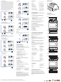
You can configure the pulse output to relate to a defined
amount of imported or exported energy. This can also be set
to use with active energy (kWh) or reactive energy (kVarh).
From the set-up menu, use
M and P buttons to
select the parity option.
Please note there are limitations that need to be factored in
when setting the pulsed output. This is based upon the relay
output only being able to pulse 2 times in one second.
For example, If the CT is set to 500/5A on a single phase
network this would generate (500Ax230V=115,000 / 1000)
115kWh which is 31W per second. A setting of 10imp/kWh
(10 pulses per kWH) would generate 3 pulses per second.
This will exceed the 2 pulse per second limitation.
Press & Hold E
to enter
the selection routine. The
current setting will flash.
Pulse settings: 1 pulse per 0.01(100W) / 0.1(10W) / 1 (1kWh) /
10(10kWh) / 100(100kWh) /1000 (1000kWh)
Use M and P buttons
to choose parity (EVEN /
ODD / NONE (default)).
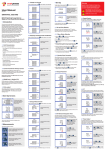
From the set-up menu,
use M and P
buttons
to select the Pulse Rate
option.
On completion of the entry procedure, Press & Hold E
confirm the setting.
Press & Hold E
to enter
the selection routine. The
current setting will flash.
0.01/0.1/1/10/100kWh/
kVArh per pulse.
• Current
0·5% of nominal
• Frequency
0·2% of mid-frequency
• Power factor
1% of unity (0.01)
• Active power (W)
±1% of range maximum
• Reactive power (VAr)
±1% of range maximum
• Apparent power (VA)
±1% of range maximum
• Active energy (Wh)
Class 1 IEC 62053-21
• Reactive energy (VARh)
±1% of range maximum
• Total harmonic distortion
1% up to 31st harmonic
• Response time to step input
1s, typical, to >99% of
final reading, at 50 Hz.
5.4 Auxiliary Supply
Two-way fixed connector with 2·5mm2 stranded wire capacity.
85 to 275V a.c. 50/60Hz ±10% or 120V to 380V d.c. ±20%.
Consumption <2W 10VA.
• RS485 communication channel that can be programmed
for Modbus RTU protocol
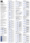
From the set-up menu, use
buttons to
M and P
select the stop bit option.
Press & Hold E
to enter
the selection routine. The
current setting will flash.
The energy monitored can be active or reactive and the pulse
width can be selected as 200, 100 or 60ms.
From the set-up menu,
use M and P
buttons
to select the Pulse width
option.
On completion of the entry procedure, Press & Hold E
confirm the setting.
to
The meter provides a function to reset the maximum demand
value of current and power.
From the set-up menu, use
buttons to
M and P
select the reset option.
There is a RS485 port can be used for communication using
Modbus RTU protocol. For Modbus RTU, parameters are
selected from Front panel.
7.1 Single Single
phasePhase,2
two wires
Wires
P1
S2
LOAD
• Relay output indicating real-time measured energy.
(configurable)
1
• Pulse output 3200imp/kWh (not configurable)
Press & Hold E
to enter
the selection routine. The
dIt will flash.
From the set-up menu,
buttons to
M and P
select the address ID.
Use M and P
buttons to choose pulse width.
On completion of the entry procedure Press & Hold E
confirm the setting.
to
5 Specifications
Press & Hold E
button
to enter the selection
routine. The current setting
will be flashing.
5.1 Measured Parameters
The unit can monitor and display the following parameters of a
single phase two wire (1p2w), three phase three wire (3p3w) or
three phase four wire (3p4w) system.
Use M and P
buttons to choose Modbus
address (001 to 247).
Rate can be set to generate 1 pulse per:
0.01 = 10 Wh/VArh
0.1 = 100 Wh/VArh
1 = 1 kWh/kVArh
10 = 10 kWh/kVArh
100 = 100 kWh/kVArh
1
2
LOAD
For Modbus RTU, the following RS485 communication
parameters
can be Phase,2
configured from
the set-up menu:
Single
Wires
Baud rate 2400, 4800, 9600, 19200, 38400
P1
S2
Parity none (default) / odd / even
LOAD
Stop bits 1 or 2
L1
L2
2
5.1.2 Power factor and Frequency and
RS485
Current inputs
Max.S0Demand
9 10 11 12 13 14 15 16 17 18 19 20
• Reactive power 0 to 3600 MVAr
• Volt-amps 0 to 3600 MVA
• Maximum demanded power since last Demand reset
Power factor
• Maximum neutral demand current, since the last Demand
reset (for three phase supplies only)
7
1 2 Energy
3
4
5
6
8
5.1.3
Measurements
Voltage inputs
L
N
L
N
• Imported/Exported active energy
0 to 9999999.9 kWh
1A FAST
1A FAST • Imported/Exported reactive energy
0 to
9999999.9 kVArh
BLOW
FUSE
BLOW FUSE
AUX
L1 • Total active energy
N
• Total reactive energy
N
1A FAST
BLOW FUSE
AUX
P1
S2
LOAD
1
P1
S2
2 B A
RS485
S0
L1
L2
L3
Current inputs
9 10 11 12 13 14 15 16 17 18 19 20
50 or 60Hz ±2%
Sinusoidal (distortion
• Input waveform
5
6
7
8 factor < 0·005)
• Auxiliary Voltage
supplyinputs
voltage L
N
L
NNominal
1
2
3
4
• Auxiliary supply frequency
Nominal
±1%
1A FAST
BLOW FUSE
Sinusoidal (distortion
factor < 0·05)
Terrestrial flux
3 Phase,3 Wires
• Operating temperature
-25°C to +55°C*
• Storage temperature
• Vibration
L3
P1
S2
2 B A
4
1A FAST
BLOW FUSE
5
6
7
8
L
N
L
N
1A FAST
BLOW FUSE
AUX
L1
L2
L3
3 Phase,4
Wires
7.3 Three phase
four wires
LOAD
Up to 3000m
1
1 minute
RS485
S0
3
L1
to 95%,
L2
non-condensing
LOAD
• Warm up time
2
Voltage inputs
-40°C to +70°C*
P1
S2
0
• Relative humidity
1
1
±1%
Current inputs
10Hz to 50Hz, IEC
60068-2-6, 2g
P1
S2
2 B A
RS485
S0
P1
S2
P1
S2
L1
L2
L3
Current inputs
9 10 11 12 13 14 15 16 17 18 19 20
30g in 3 planes
*Maximum operating and storage temperatures are in the
context of typical daily and seasonal variation.
• Power 0 to 3600 MW
to
23°C ±1°C
• Input waveform
• Shock
• Instantaneous power:
Use M and P
buttons to choose Baud
rate 2.4k. 4.8k, 9.6k,
19.2k, 38.4k
• Ambient temperature
9 10 11 12 13 14 15 16 17 18 19 20
• Frequency in Hz
Press & Hold E
to enter
the selection routine. The
current setting will flash.
8
L
Influence Quantities are variables that affect measurement
errors to a minor degree. Accuracy is verified under nominal
value (within the specified tolerance) of these conditions.
• Altitude
B A
7
N
5.6 Reference Conditions of Influence
Quantities
5.7 Environment
1
6
L
3 Phase,3
7.2 Three phase
three Wires
wires
9 10 11 12 13 14 15 16 17 18 19 20
• Voltages between phases 173 to 500V a.c.
(3p supplies only).
• Current THD% for each phase
5
N
Modbus™ Word order Hi/Lo byte order is set automatically to
normal or reverse.
ItRS485
cannotCurrent
be configured
from the
inputs
S0
set-up menu.
• Magnetic
field of external origin
N
L2
4
1A FAST
BLOW FUSE
5.5.2 RS485 Output for Modbus RTU
• Phase to neutral voltages 100 to 289V a.c.
(not for 3p3w supplies).
• Percentage voltage THD% between
phases
P1
L1
(three phase supplies only). S2
3
Voltage inputs
L1
L1
Single Phase,2
• Percentage
total voltageWires
harmonic distortion (THD%) for
each phase to N ( not for 3p3w supplies).
4.8.2 Baud Rate
Current inputs
5.5.1 Pulse Output
1A FAST
BLOW
FUSE supply waveform (if AC)
• Auxiliary
AUX
5.1.1 Voltage and Current
On completion of the entry procedure, Press & Hold E
button to confirm the setting.
RS485
9 10 11 12 13 14 15 16 17 18 19 20
RS485 network
address
1
2 B A nnn – 3-digit number, 1 to 247
4.8.1 RS485 Address
L1
L2
2 B A
S0
The Modbus configuration (baud rate etc.) and the pulse
relay output assignments (kW/kVArh, import/export etc.)
are configured through the set-up screens.
Pulse width 200/100/60 ms.
4.9 CLR
to
7 Installation
Opto-coupler with potential free SPST-NO Contact
(Contact range 5-27VDC / Max current input: Imin 2mA and
Imax 27mA DC). The pulse output can be set to generate
pulses to represent kWh or kVArh.
Use M and P
buttons to choose stop
bit (2 or 1)
4.8 Communication
On completion of the entry procedure, Press & Hold E
confirm the setting.
0·5% of range maximum
Three interfaces are provided:
4.7.2 Pulse Duration
From the set-up menu,
use M and P
buttons
to select the Baud Rate
option.
• Voltage
5.5 Interfaces for External Monitoring
Use M and P
buttons to choose pulse rate. On
completion of the entry procedure, Press & Hold E
to
confirm the setting.
Use M and P
buttons to choose pulse width.
On completion of the entry procedure Press & Hold E
confirm the setting.
to
4.8.4 Stop bits
Press & Hold E
to enter
the selection routine. The
current setting will flash.
6 Dimensions
5.3 Accuracy
0 to 9999999.9 kWh
0 to 9999999.9 kVArh
5.2 Measured Inputs
Voltage inputs through 4-way fixed connector with 2.5mm²
stranded wire capacity. Single phase two wire(1p2w), three
phase three wire(3p3w) or three phase four wire(3p4w)
unbalanced. Line frequency measured from L1 voltage
or L3 voltage. Three current inputs (six physical terminals) with
2.5mm² stranded wire capacity for connection of external CTs.
Nominal rated input current 5A or 1A a.c. Rms.
Smart Process & Controls Ltd, 11 Totman Close, Brook Road Industrial Estate, Rayleigh, Essex SS6 7UZ
Customer Service: 01268 773422 | www.smartprocess.co.uk | Specifications are subject to change without notice
5.8 Mechanics
• DIN rail dimensions
72 x 94.5 mm (WxH)
per DIN 43880
• Mounting
DIN rail (DIN 43880)
• Sealing
1
• Material
2
3
4
Voltage inputs
1A FAST
BLOW 5.9
FUSEDeclaration
5
6
7
8
L
N
L
N
IP51 indoor
1
Self-extinguishing UL
94 V-0
1A FAST
BLOW FUSE
ofAUX
Conformity
L1
L2
L3
Declare
under our sole responsibility as the manufacturer
We Smart Process & Control LTD.
that the poly phase multifunction electrical energy meter
“SMARTRAIL X835mv” correspond to the production model
described in the EC-type examination certificate and to the
requirements of the Directive 2004/22/EC EC type examination
certificate number 0120/SGS0150. Identifcation number of the
NB 0120.
2
3
Voltage inputs
1A FAST
BLOW FUSE
L1
L2
L3
N
4
5
6
7
8
L
N
L
N
AUX
1A FAST
BLOW FUSE