1
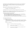
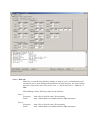
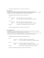
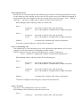
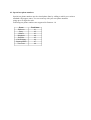
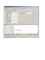
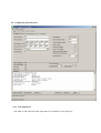
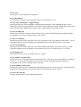
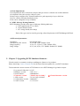
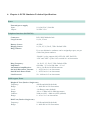
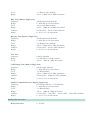
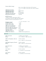
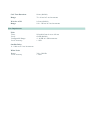
SIM2FXSA Phone Line Simulator User Manual 2.1 Updated March 2006 © 20022006 NTS Telecom Ltd & Virtual Console, LLC All Rights Reserved. Table of Contents 1. Chapter 1: Important Information 1.1. General Disclaimer 1.2. Other Restrictions 1.3. Trademark Information 1.4. Patent information 1.5. Warranty 1.6. Limitation of Remedies and Damages 1.7. Important Safeguards 1.8. Regulatory Compliance 2. Chapter 2: Introduction. Overview of PSTN Simulator 2.1. Functional Overview 2.2. Overview of FXS ports 2.3. DB9 port 2.4. Power Adapter 3. Chapter 3: Getting started with PSTN Simulator 3.1. Connecting PSTN Simulator to a PC 3.2. Powering up PSTN Simulator 3.3. Installing PSTN Manager Software 3.4. Connecting analogueue telephones to simulator 4. Chapter 4: Configuring simulator with PSTN Manager 4.1. Replicating configuration among FXS ports 4.2. Configuring Global Parameters 4.2.1. Configuring Call Progress Tones. 4.2.1.1. Dial Tone 4.2.1.2. Busy Tone 4.2.1.3. Ringback Tone 4.2.1.4. Reorder Tone 4.2.1.5. Call Waiting Tone 4.2.1.6. Test Tone 4.2.2. Disconnect treatment 4.2.3. Maximum flash onhook time 4.2.4. Minimum flash onhook time 4.2.5. Disconnect timeout 4.2.6. Dial tone delay 4.2.7. Network response delay 4.2.8. Response to busy 4.2.9. Response to invalid number 4.3. Special test phone numbers 4.4. Configuring FXS interfaces 4.4.1. Line impedance 4.4.2. Assigning Phone numbers 4.4.3. Configuring ring cadence 4.4.4. Off hook mode 4.4.5. Input/Output amplification 4.4.6. Detect “Flash” 4.4.7. Detect Pulse dialing 4.4.8. Detect Tone dialing 4.4.9. Polarity Reversal for Metering 4.5. Configuring Caller ID 4.5.1. Caller ID Overview 4.5.2. Caller ID Data 4.5.2.1. Date and Time 4.5.2.2. Calling Number 4.5.2.3. Calling Name 4.5.3. Caller ID Localisation 4.5.3.1. Advanced Caller ID Settings 4.5.3.2. Type 4.5.3.3. Modulation 4.5.3.4. SDMF MDMF 4.5.3.5. First Ring On 4.5.3.6. Pre CID Delay 4.5.3.7. Post CID Delay 4.5.3.8. Signal Level 4.5.3.9. Number of Seizure Bits 4.5.3.10. Number of Mark Bits 4.5.3.11. UK Caller ID 4.6. Line Impairements 4.7. MWI Message Waiting Indicator 4.8. Electrical Parameters 5. Chapter 5: Upgrading PSTN Simulator firmware 6. Chapter 6: PSTN Simulator Technical Specifications 7. Chapter 7: Glossary 8. Chapter 8: Contact Details 1. Chapter 1: Important information 1.1 General Disclaimer No part of this document can be reproduced or transmitted in any form or by any means, electronic or mechanical, for any purpose without the written express permission from NTS Telecom Ltd. Under the law reproducing includes translating into another language or digital format. As between the parties, Virtual Console, LLC retains title to, and ownership of, all proprietary rights with respect to the software contained within its products. The software is protected by United States and international copyright laws. Therefore, you must treat the software like any other copyrighted material. 1.2 Other Restrictions You shall not and shall not allow any third party to decompile, disassemble, reverseengineer or attempt to reconstruct or discover any source code or underlying ideas or algorithms of the software by any means whatsoever or remove any product. 1.3 Trademark Information Virtual Console ® logo design is registered trademark in the United States and various other countries. Microsoft®, Windows® are registered trademarks or trademarks of Microsoft Corporation. All other trademarks are the property of their respective owners. Every effort has been made to ensure that the information in this manual is accurate. Information in this document is the subject to change without notice. 1.4 Patent Information The accompanying product is protected by one or more U.S. and foreign patents and patents pending held by Virtual Console, LLC 1.5 Warranty Virtual Console, LLC warrants its products to be free of defects in materials and factory workmanship for a period of twelve (12) months from date of purchase. This warranty does not apply to damage to products resulting from accident, misuse, service or modification by anyone other than a Virtual Console, LLC authorized service facility/dealer. The warranty is limited to the original purchaser and is not transferable. Any liability of Virtual Console or its suppliers with respect to the product or the performance thereof under any warranty, negligence, strict liability or other theory will be limited exclusively to product repair or replacement as provided above. Except for the foregoing, the product is provided “as is” without warranty of any kind including without limitation, any warranty of merchantability or fitness for a particular purpose. The entire risk of the quality and performance of the software programs contained in the system is with you. 1.6 Limitation of Remedies and Damages Virtual Console, LLC, its agents, employees, suppliers, dealers and other authorized representatives shall not be responsible or liable with respect to the product or any other subject matter related thereto under any contract, negligence, strict liability or other theory for any indirect, incidental, or consequential damages, including, but not limited to loss of information, business, or profits .The law of certain states or nations does not permit limitation or exclusion of implied warranties and consequential damages, so the above limitations, disclaimers, or exclusion may not apply to you. This warranty gives you special legal rights. You may also have other rights that vary by state and nation. 1.7 Important Safeguards Read and understand the following instructions before using the system: Close supervision is necessary when the system is used by or near children. Do not leave unattended while in use. Always disconnect the system from power before cleaning and servicing and when not in use. Do not spray liquids directly onto the system when cleaning. Always apply the liquid first to a static free cloth. Do not place this product onto unstable desk, cart or table. The product may fall causing serious damage to the product. Do not immerse the system in any liquid or place any liquids on it. Do not disassemble this system (except as instructed in the manufacturer's instructions). To reduce the risk of shock and to maintain the warranty on the system, a qualified technician must perform service or repair work. Connect this appliance to a grounded outlet. Connect the system only to surge protected power outlets. Keep ventilation openings free of any obstructions. Unplug this product from the wall outlet and refer servicing to qualified service personnel under the following conditions: 1. When the power supply adapter or plug is damaged or frayed. 2. If liquid has been spilled into the product. 3. If the product has been exposed to rain or water. 8. If the product has been dropped or the enclosure has been damaged. 9. If the product exhibits a distinct change in performance. SAVE THESE INSTRUCTIONS 1.8 Regulatory Compliance This equipment has been tested and found to comply with the limits for a Class A digital device, pursuant to Part 15 of the FCC Rules. These limits are designed to provide reasonable protection against harmful interference when the equipment is operated in a commercial environment. This equipment generates, uses and can radiate radio frequency energy and, if not installed and used in accordance with the instruction manual, may cause harmful interference in which case the user will be required to correct the interference at his own expense. 2. Chapter 2: Introduction. Overview of PSTN simulator 2.1. Functional Overview PSTN (Public Switched Telephone Network) Simulator provides an analogue PSTN call switching service eliminating the expense of the real phone lines for testing or demonstrating devices that require analogueue (FXS). PSTN Simulator gives access to the rich set of configurable parameters from electrical to line impairments making it a valuable tool for telecom designers and developers. PSTN simulator comes with 2 analogueue (FXS) loop start ports. 2.2. Overview of FXS ports FXS (Foreign Exchange Station) ports are commonly used to connect analogueue telephone sets to a CO (Central Office) They can be found as a regular RJ11 wall jacks in every household or offices with analogueue telephone lines. RJ11 jacks usually equipped with 6 pins, but only pins 3 and 4 are being used. PSTN simulator comes with 8pin RJ45 jacks where only pins 4 and 5 are being used. PSTN Simulators can accept standard RJ11 connector without any additional rewiring. Depending on country of use, UK BT style adaptors including ring capacitors are provided. Each FXS port on PSTN simulator has two integrated Green LED: Left and Right. LEDs on FXS ports provide visual indication for call progress states, indication of Connect, Disconnect, on hook and off hook modes. LED Right LED OFF LEFT LED OFF Right LED Solid GREEN Right LED Blinking GREEN Left LED Solid GREEN Left LED Blinking GREEN 2.3. DB9 port (COM Port) Indication/Legend Telephone set is ON HOOK or not Connected No active or in progress outgoing calls Telephone set if OFF HOOK Incoming call is in progress Call is established Outgoing call is in progress DB9 port provides communication between PSTN simulator and PSTN Manager application which runs on Windows platform. Standard straightthrough Serial cable should be used to connect simulator to a PC. 2.4. Power Adapter PSTN simulator is shipped with a desktop or wall type power adapter with a 2.5mm output jack. PSTN simulator can accept power source with a range of 12V20V AC or DC with a current rating of 1.5A . Switching or Linear adapters can be used. For applications that require low noise levels linear adapters are recommended. Please be aware that power adapter can get warm during normal operation and require proper ventilation to operate. Do not block airflow to and from power adapter. PSTN simulator is not designed for nonstop 24x7 operations. Keep it turned off while not in use. 3. Chapter 3: Getting started with PSTN Simulator 3.1. Connecting PSTN simulator to a PC After unpacking your PSTN simulator, connect DB9 port on a simulator to a COM port on your PC with a supplied RS232 cable. RS232 cable is included with every simulator sold. RS232 cable is a standard straightthrough serial cable with 9 pins Male/Female connectors. 3.2. Powering up PSTN simulator Make sure that Power switch is in OFF position. Connect output power jack from power adapter to a DC jack on a simulator labelled “Power” Turn power switch into an ON position 3.3. Installing PSTN Manager software Install PSTN Manager application from the floppy or CD which came with a simulator kit. PSTN Manager requires 2Mb of free space on your hard drive and can be installed on any Windows platform. 3.4. Connecting analogue telephones to simulator To connect analogue telephones to FXS ports you can use regular RJ11 cables which are usually supplied with a telephones. Thought FXS ports on simulator are equipped with RJ45 jacks they can accept RJ45 connectors as well. You can test the connection by lifting a handset and verifying a presence of the dial tone. 4. Chapter 4: Configuring simulator with PSTN Manager Using PSTN Manager is the only way of configuring the simulator. Some of the features in PSTN Manager do not apply to this version of the Simulator. These features are greyed out if they do not apply. Any changes that you make in PSTN Manager do not take an effect until you save the configuration to PSTN simulator. Some of the changes can be applied ‘on the fly’ and some requires a reboot of the simulator. PSTN Manger will determine if the Reboot is required and automatically reboot the simulator if needed. Please note that all established calls will be lost if simulator is rebooted. You can also save your current configuration to a file on the disk by accessing a “Main Menu > File> Save Config” interface. The CDROM supplied with the simulator has suggested configuration files for various countries. PSTN Manager is a set of configuration Tabs for Global (applicable to all ports) and Local (port specific) parameters. The actual set of parameters is based on firmware version and firmware feature set installed and activated on a particular PSTN simulator. 4.1. Replicating configuration among FXS ports You can easily replicate changes made on a single FXS port To: or From: particular FXS port by using a “Copy configuration” button on each FXS port configuration tab. You can copy configuration from the current port to all FXS ports or a particular FXS port number. or you can copy configuration from any FXS port number to a current FXS port. Please note that Phone numbers and Caller ID information will not be copied as a part of this process. 4.2. Configuring Global Parameters 4.2.1. Configuring call progress tones Call progress tones can be configured as a single or dual tone bands with a specific frequency, cadence and signal power. Different countries has deployed different standards for call progress tones. Refer to an ITU E.180 standard for further details on country specific call progress tones. Three primary standards are: Single tone: Tone consist of a single tone at a given frequency Dual tone: (Tone 1 + Tone 2): Tone is the result of a sum of two tones. Each tone has its own frequency. Dual tone: (Tone 1 x Tone 2): Tone is the result of Tone1 modulated by Tone 2. Each tone has its own frequency 4.2.1.1. Dial tone Dial tone is a tone advising that the exchange is ready to receive call information and inviting the user to start sending call information. In North America, the most common dial tone consist of the sum of two tones: Tone 1 = 350 Hz and Tone 2 = 440Hz at 13 dBm. PSTN Manager allows following values for the dial tone: Tone 1: Frequency: Power: from 0 Hz to 3999 Hz with 1 Hz increments. from 100.00 dBm to 3.00 dBm with 0.01 dBm increments Tone 2: Frequency: Power: from 0 Hz to 3999 Hz with 1 Hz increments. from 100.00 dBm to 3.00 dBm with 0.01 dBm increments To hear the configured Dial tone, call special test number 01. 4.2.1.2. Busy tone Busy tone is tone advising the caller that the called party is engaged in another call. In North America, the most common busy tone consists of the sum of two tones: Tone 1 = 480 Hz and Tone 2 = 620 Hz at 24 dBm with cadence of 500ms ON, 500ms OFF PSTN Manager allows following values for the busy tone: Tone 1: Frequency: Power: from 0 Hz to 3999 Hz with 1 Hz increments. from 100.00 dBm to 3.00 dBm with 0.01 dBm increments Tone 2: Frequency: Power: from 0 Hz to 3999 Hz with 1 Hz increments. from 100.00 dBm to 3.00 dBm with 0.01 dBm increments Cadence: 0 9999ms ON, 09999ms OFF with 1ms increments To hear the configured busy tone, call special test number 02. 4.2.1.3. Ringback Tone Ringback tone is a tone advising the caller that a connection has been made and that a calling signal is being applied to a telephone number or service point. In North America, the most common ringback tone consists of the sum of two tones: Tone 1 = 440 Hz and Tone 2 = 480 Hz at 16 dBm with a cadence of 2000ms ON, 4000ms OFF. PSTN Manager allows following values for the ringback tone: Tone 1: Frequency: Power: from 0 Hz to 3999 Hz with 1 Hz increments. from 100.00 dBm to 3.00 dBm with 0.01 dBm increments Frequency: Power: from 0 Hz to 3999 Hz with 1 Hz increments. from 100.00 dBm to 3.00 dBm with 0.01 dBm increments Tone 2: Cadence: 0 9999ms ON, 09999ms OFF with 1ms increments To hear the configured ringback tone, call special test number 04. 4.2.1.4. Reorder Tone Reorder tone is a tone advising the caller that the groups of lines or switching equipment necessary for the settingup of the required call or for the use of a specific service are temporarily engaged. In North America, the most common reorder tone consists of the sum of two tones: Tone 1 = 480 Hz and Tone 2 = 620 Hz at 16 dBm with a cadence of 2500ms ON, 250ms OFF PSTN Manager allows following values for reorder tone: Tone 1: Frequency: Power: from 0 Hz to 3999 Hz with 1 Hz increments. from 100.00 dBm to 3.00 dBm with 0.01 dBm increments Frequency: Power: from 0 Hz to 3999 Hz with 1 Hz increments. from 100.00 dBm to 3.00 dBm with 0.01 dBm increments Tone 2: Cadence: 0 9999ms ON, 09999ms OFF with 1ms increments To hear the current reorder tone, call special test number 05. 4.2.1.5. Call Waiting Tone Call waiting tone is a tone advising the user of the call waiting supplementary service who is engaged on a call that someone is attempting to call his number. In North America, the most common Call Waiting tone consists of single tone: Tone 1 = 440 Hz at 13 dBm with a cadence of 300ms ON, 10000ms OFF. PSTN Manager allows following values for Call Waiting tone: Tone 1: Frequency: Power: from 0 Hz to 3999 Hz with 1 Hz increments. from 100.00 dBm to 3.00 dBm with 0.01 dBm increments Frequency: Power: from 0 Hz to 3999 Hz with 1 Hz increments. from 100.00 dBm to 3.00 dBm with 0.01 dBm increments Tone 2: Cadence: 0 9999ms ON, 09999ms OFF with 1ms increments To hear the configured call waiting tone, call special test number 06. 4.2.1.6. Test Tone Test tone is a nonstandard tone of the user’s choice. PSTN Manager allows following values for the test tone: Tone 1: Frequency: from 0 Hz to 3999 Hz with 1 Hz increments. Power: from 100.00 dBm to 3.00 dBm with 0.01 dBm increments Frequency: Power: from 0 Hz to 3999 Hz with 1 Hz increments. from 100.00 dBm to 3.00 dBm with 0.01 dBm increments Tone 2: To hear the configured test tone, call special test number 08. 4.2.2. Disconnect Supervision “Disconnect Supervision” defines how PSTN Simulator treat an event when Called part disconnects. In the event when called party disconnects Calling party can have one type of inband audio signal such as Busy or Dialtone or Reorder or Silence. Those inband signals can be used by DSP based systems for correct detection of disconnect event. In addition to inband signal Simulator can advise Calling party by short Polarity Reversal (Battery Reversal) or brief loss of current supplied to a line. Options Loss of Current and Polarity Reversal can be used at the same. 4.2.3. Maximum Flash onhook time “Maximum Flash onhook time” defines the border line between “Flash” and “On Hook” events. Pressing a hook for less than this time will result in a “Flash”, pressing a hook for a longer than this time will result in an “On Hook” event. Default timer value is 700ms. PSTN Manager allows following values for the “Maximum Flash onhook time”: From 0ms to 65535ms with 1ms increment. 4.2.4. Minimum Flash onhook time “Minimum Flash onhook time” defines a minimum time hook has to be pressed to generate a “Flash”. Pressing a hook for less than this time will not have any result, pressing a hook for a longer than this time will result in “Flash” event. Default timer value is 100ms. PSTN Manager allows following values for the “Minimum Flash onhook time”: From 0ms to 65535ms with 1ms increment. 4.2.5. Disconnect timeout “Disconnect timeout” defines a minimum time that the hook has to be pressed to generate an “On Hook” event. Default timer value is 1000ms. PSTN Manager allows following values for the “Disconnect timeout”: From 0ms to 65535ms with 1ms increment. 4.2.6. Dial tone delay “Dial tone delay” is the timer that defines how soon the user will hear a dial tone after lifting a handset. Default timer value is 200ms. PSTN Manager allows following values for the “Dial tone delay”: From 0ms to 65535ms with 1ms increment. 4.2.7. Network response delay “Network response delay” is a timer that defines how soon the user will hear Ringback after dialling the destination phone number. Default timer value is 500ms. PSTN Manager allows following values for the “Network response delay”: From 0ms to 65535ms with 1ms increment. 4.2.8. Response to busy “Response to Busy” defines which tone calling party will hear when the called party is engaged in another call. Default value is: Busy PSTN Manager allows following values for the “Response to busy” Busy (Calling party will hear a busy tone) Reorder (Calling party will hear a reorder tone) 4.2.9. Response to invalid number “Response to invalid number” defines which tone the calling party will hear when the called number does not exist. Default value is: Busy PSTN Manager allows following values for the “Response to invalid number”: Busy (Calling party will hear a busy tone) Reorder (Calling party will hear a reorder tone) Silence (Calling party will hear nothing) 4.3. Special test phone numbers Special test phone numbers are the virtual phone lines by calling to which you can hear standard call progress tones. You can come up with your own phone numbers using up to 16 digits for each. Following test phone numbers are supported in firmware 1.0 Event Dial tone Busy Silence Ringback Reorder Call Waiting Stuttered Dial Test Tone Test Phone 01 02 03 04 05 06 07 08 4.4. Configuring FXS interfaces 4.4.1. Line impedance 600 Ohm or 900 Ohm selectable impedance is available for each FXS port 4.4.2. Assigning Phone numbers There are two phone numbers that can be assigned to each FXS port. Each number can be from 1 to 16 digits long. You can dial either one to call a particular FXS port. You can use secondary phone numbers to create a Hunt Groups or to test custom ring cadences. Default numbers for each port are two digit numbers: FXS 1 FXS 2 First number 11, Second number 12 First number 21, Second number 22 4.4.3. Configuring ring cadence Cadence is the rhythm of the ring voltage applied to a telephone connected to FXS port. It is defined as a sequence of ON and OFF timers. You can configure two ring cadences for each FXS port. One cadence for each phone number. Default value for Phone 1 is: 1000ms ON, 3000ms OFF Default value for Phone 2 is: 500ms ON, 400ms OFF, 500ms ON, 400ms OFF, 2000ms OFF PSTN Manager allows following values for the Cadence timers: From 0ms to 9999ms with 1ms increment Note: Using a 0 value for the first ON timer will prevent a ring on that FXS port 4.4.4. Off hook mode “Off hook mode” defines how PSTN simulator must treat an OFF hook even on particular FXS port. Default value is “Standard”. PSTN simulator will provide a Dial tone and will wait for the called number to be dialled manually. PSTN Manager allows following values for the “Off Hook mode”: Standard (Default) Hotline aka PLAR (Simulator automatically dials to a preconfigured phone number from the “Hotline” filed) Do nothing (no dial tone will be provided) 4.4.5. Input/Output amplification “Input and Output amplification” defines amplification in dB that will be applied to a signal which comes from/to a connected telephone set to a particular FXS port. Default value is: 0.00 dB (no amplification) PSTN Manager allows following values for the “Input” and “Output” amplification: From 100 dB to + 30dB with 0.01 dB increment 4.4.6. Detect “Flash” Check button “Detect Flash” turns “ON” detection of the “Flash” event. “Flash” is an event of pressing a telephone’s hook for a time between “Min and Max Flash on hook time” defined in Global parameter tab. 4.4.7. Detect Pulse dialling Turns ON and OFF detection of Pulse dialling Default is: ON 4.4.8. Detect Tone dialling Turns ON and OFF detection of Tone dialling Default is: ON 4.4.9. Polarity Reversal for Metering Some applications such as pay phones and billing systems require polarity reversal to occur in a predefined interval for correct billing calculation. You can enable Metering polarity Reversal on each FXS port and Polarity Reversal will occur every 60 seconds (60 seconds is default). It can be adjusted to a lesser or greater time interval. 4.5. Configuring Caller ID 4.5.1. Caller ID Overview Caller ID is the feature of the PSTN simulator which delivers the calling party phone number and name to the telephone set of the called party. This service gives the called party ability to identify caller by telephone number or name even before answering the phone or when is on call with a third party. Fig: Caller ID Type I transmission flow without line reversal 4.5.2. Caller ID Data Sets the Caller ID information for calls originating from the individual FXS port 4.5.2.1. Date and Time Allows setting of Caller ID date and time. 4.5.2.2 Calling Number A custom number can be set, one of the ports numbers, or absent. 4.5.2.3 Calling Name A custom name or absent can be set. 4.5.3 Caller ID Localisation Allows customisation of Caller ID to various International Standards. Supported localisations are US, UK FSK with line reversal, ETSI FSK, and ETSI DTMF. 4.5.3.1 Advanced Caller ID Settings Depending on the localisation selected, various parameters are available for customisation. 4.5.3.2 Type Only Type 1 on hook Caller ID is supported. 4.5.3.3 Modulation For FSK based Caller ID, the modulation can be set to Bell 202 or V.23. 4.5.3.4 Caller ID multiple or single message Single Data Message Format (SDMF) or Multiple Data Message Format (MDMF) defines which information delivered to the called party as a part of Caller ID Data message. SDMF delivers date, time and a calling number. MDMF delivers date, time, calling number and a caller’s name. 4.5.3.5 First Ring On Defines the time for the duration of the first ring burst. In the Caller ID transmission flow diagram it corresponds to the Event A. Default value is 1.0 second. 4.5 3.6 Pre CID Delay Defines the timeout between the end of the first ring and the start of the channel seizure block. . In the Caller ID transmission flow diagram it corresponds to the Event B. Default value is 0.6 second. 4.5.3.7 Post CID Delay Defines the timeout between the end of the Caller ID data transmission and the second ring. In the Caller ID transmission flow diagram it corresponds to the Event F. Default value is 1.0 second. 4.5.3.8 Signal Level Allows the FSK level to be set. Default value is 3 dBm. 4.5.3.9 Number of Seizure bits Defines the block of continuous bits of alternating 0 and 1. The first bit to be transmitted is 0 while the last bit is 1. It is used for Caller ID Type I only. In the Caller ID transmission flow diagram it corresponds to the Event C. Default value is 300 bits. 4.5.3.10 Number of Mark bits Defines the number of bits of continuous high transmitted after the seizure bits block. In the Caller ID transmission flow diagram it corresponds to the Event D. Default value is 200 bits. 4.5.3.11 UK Caller ID Defines delay after line reversal and alert duration. 4.6 Line Impairments Line impairments allow software developers and QA testers to simulate real world conditions On telephone lines such as noise, delays or echo. Delays can be configured for Transmit and Receive path separately for up to 2000 ms. Noise is a White Gaussian distribution noise. Echo can be configured for up to 2000ms 4.7 MWI. Message Waiting Indicator PSTN Simulator provides three types of Message Waiting Indicators a. FSK signal based (V.23 or Bell) b. Stutter Dialtone based c. DC voltage based (neon lamp) Each of the types can be tested by pressing a Start/Stop buttons in PSTM Manager MWI tab. 4.8 Electrical parameters Impedance: Off hook loop DC current: Ring Frequency: Ring Voltage: 600 and 800 Ohm 10, 20 and 32mA. Default 32mA 16, 20, 25, 35, 50 65, 75Hz. Default 25Hz 30, 35, 40, 45, 50, 55 V (RMS). Default 55V (RMS) 5. Chapter 5: Upgrading PSTN Simulator firmware Virtual console is constantly working on adding new features to its products. Please check http://www.vconsole.com for the latest firmware updates for your PSTN simulator. To determine the current version of FXS firmware use a PSTN Manager log window output: * Log started 1May04 19:21:55 * Hardware version: “VH.2.2.1.1” * Serial Number: “0000000000” * Firmware version: “V01.03 (Apr 30 2004)” * AVR version: “V01.01 (Apr 14 2004)” * Configuration version: “00040100” * Codec revision: “15/15/15/15” ß Chassis firmware version 6. Chapter 6: PSTN Simulator Technical Specifications Power External power supply Input: Output: 110240 VAC, 50/60 Hz 20 VDC 1.5A Telephone Interface (POTSFXS) Connector: Loop Current: RJ11/RJ45 Modular Jack 10, 20, 35 mA Battery Source: Ringing Source: Ring Cadence: 48 VDC 16, 20, 25, 35, 50 65, 75Hz. Default 25Hz Up to two distinctive cadences can be assigned per port, one per each of the phone numbers. “Double” cycles support (ON, OFF, ON, OFF, PAUSE) “ON” and “OFF” cycles: 065 seconds in 1 ms increments Ring Frequency : Impedance: Attenuation/Amplification: Onhook Disconnect Timeout: On/Offhook Detect Flash: Line Reversal: 16, 20, 25, 35, 50 65, 75Hz. Default 25Hz 600 Ohm + 2.2 uf or 800 Ohm + 2.2 uf 90 to +30 dB in 0.01 dB increments. 1 65535 ms in 1 ms increments 1 65535 ms in 1 ms increments 50 1000 ms in 5 ms increments Call Progress Tones Ringback Tone (Dual or Single tone) Frequency: 440 Hz and 480 Hz (default) Range: 0 4000 Hz in 1 Hz increments Level: 16 dBm per tone (default) Range: 90 to +3 dBm in 0.01 dBm increments Cadence: 2000 ms (ON) – 4000 ms (OFF) (default) Range: 0 65 sec. in 1 ms increments Dial Tone (Dual or Single tone) Frequency: Range: 350 Hz and 440 Hz (default) 0 4000 Hz in 1 Hz increments Level: Range: 13 dBm per tone (default) 90 to +3 dBm in 0.01 dBm increments Busy Tone (Dual or Single tone) Frequency: Range: Level: Range: Cadence: Range: 440 Hz and 620 Hz (default) 0 4000 Hz in 1 Hz increments 24 per tone dBm (default) 90 to + 3 dBm in 0.01 dBm increments 500 ms (ON) – 500 ms (OFF) (default) 0 65 sec. in 1 ms increments Reorder Tone (Dual or Single tone) Frequency: 480 Hz and 620 Hz (default) Range: 0 4000 Hz in 1 Hz increments Level: 16 dBm per tone (default) Range: 90 to +3 dBm in 0.01 dBm increments Cadence: 250 ms (ON) – 250 ms (OFF) (default) Range: 0 65 sec. in 1 ms increments Test Tone Frequency: Range: Level: 1004 Hz (default) 0 to 4000 Hz in 1 Hz increments 90 to + 3 dBm in 1 dBm increments Call Waiting Tone (Dual or Single tone) Frequency: 440 Hz single (default) Range: 0 4000 Hz in 1 Hz increments Level: 13 dBm (default) Range: 90 to +3 dBm in 0.01 dBm increments Cadence: 300 ms (ON) – 10000 ms (OFF) (default) Range: 0 65 sec. in 1 ms increments Number Unobtainable Tone (Dual or Single tone) Frequency: 950 Hz and 1400 Hz ± 1 Hz (Default) Range: 0 4000 Hz in 1 Hz increments Level: 13 dBm (default) Range: 90 to + 3 dBm in 1 dBm increments Cadence: 330 ms (ON) – 5 ms (OFF) – 330 ms (ON) – 5 ms (OFF) (default) Range: 0 10 sec. in 5 ms increments Dialing Characteristics Rotary Detection 8 30 PPS Percent ‘Break' range: Minimum break time: Maximum break time: Minimum make time: Maximum make time: Minimum interdigit time: Ring trip detection time: 40 ms / 60 ms Make / Break ratio (US, Germany) 33 ms / 67 ms Make / Break ratio (UK, France, Ireland) 6 ms programmable 6 ms programmable programmable 2 periods DTMF Detection Complies with the requirements of ITUT Q.24, BellCore GR30CORE (TRNWT000506) Deutsche Telecom network (BAPT 223 ZV 5) Frequency accept: Frequency reject: Positive twist accept: Negative twist accept: Min tone accept duration: Max tone reject duration: Min interdigit pause duration: Max tone dropout duration: Signaling velocity: Signal detection level: DTMF noise tolerance: < ± 1.5% (+4 Hz) and <± 1.8% > ± 3% < 8 dB < 8 dB 40 ms 25 ms 40 ms 20 ms >= 93 ms/digit 48 to 0 dBm 12dB to lowest amplitude tone Caller ID FSK Tone Level: Range: 15 dBm per tone (default) 10 to 60 dBm in 1 dBm increments FSK Low Frequency (Tone 1): Range: 1200 Hz (default) 1100 1400 Hz in 1 Hz increments FSK High Frequency (Tone 2): Range: 2200 Hz (default) 2000 2300 Hz in 1 Hz increments CAS Tone Level: Range: 15 dBm per tone (default) 6 to 60 dBm in 1 dBm increments CAS Tone 1: Range: 2130 Hz (default) 10 3000 Hz in 1 Hz increments CAS Tone 2: Range: 2750 Hz (default) 10 3000 Hz in 1 Hz increments CAS Tone Duration: Range: 80 ms (default) 70 90 ms in 5 ms increments Wait for ACK: Range: 160 ms (default) 100 – 300 ms in 5 ms increments Line Impairments Echo Time: Level: Configurable Range: Level Accuracy: Selectable from 0 ms to 100 ms 60 dB (default) 4 60 dB in 1 dB increments ± 1 dB Satellite Delay 0 – 1000 ms in 1 ms increments White Noise Range: Level Accuracy 300 3400 Hz ± 2 dB 7. Chapter 7: Glossary of Terms Busy Tone A tone advising the caller that the telephone number is busy. Call Waiting A service feature that provides an indication to a terminal already engaged in an established call that one or more calls are awaiting connection. Call Waiting Tone A tone advising the user of the call waiting supplementary service who is engaged on a call that someone is attempting to call his number. Caller ID A network service feature that permits the recipient of an incoming call to determine, even before answering, the number from which the incoming call is being placed. CO (Central Office) Local telephone company office where all local loops in a given area connect and circuit switching of subscriber lines occurs. Congestion Tone A tone advising the caller that the groups of lines or switching equipment necessary for the settingup of the required call or for the use of a specific service are temporarily engaged. CPE (Customer Premises Equipment) Communications equipment that resides on the customer's premises. dB Abbreviation for decibel. One tenth of the common logarithm of the ratio of relative powers, equal to 0.1 B (bel). dBm Abbreviation. dB referenced to one milliwatt. dBm is used in communication work as a measure of absolute power values. Zero dBm equals one milliwatt. Dial Tone A tone advising that the exchange is ready to receive call information and inviting the user to start sending call information. DTMF Dual Tone Multi Frequency. The signal a telephone company receives when a telephone's touch keys are pressed. Also known as Touchtone. Flash While the phone is offhook, quickly pressing and releasing the flash hook to signal the central office or PBX that you are requesting special processing, for example, call waiting. Flash hook The plunger the phone's handset rests on while onhook. FSK (frequencyshift keying) Frequency modulation in which the modulating signal shifts the output frequency between predetermined values. FXO (Foreign Exchange Office) FXO interface connects to the Public Switched Telephone Network (PSTN) central office and is the interface offered on a standard telephone. FXO interface is an RJ11 connector that allows an analogue connection at the PSTN's central office or to a station interface on a PBX. FXS (Foreign Exchange Station) FXS interface connects directly to a standard telephone and supplies ring, voltage, and dial tone. FXS interface is an RJ11 connector that allows connections to keysets, and PBX. ITUT International Telegraph and Telephone Consultative Committee. International body that develops worldwide standards for telecommunications technologies. Impedance The combined effect of resistance, inductance and capacitance on a transmitted signal. Impedance varies at different frequencies. Loop Start A twoway, twowire (tip and ring) signaling method in which the current used for signaling flows in a circuit (loop) between a telephone and PBX or a telephone and central office. Seizure of the line is accomplished by going offhook which causes current to flow in a circuit (loop). Loop Current The current that flows through the circuit from the telephone switch to the voice board when the channel is offhook Onhook The signalling state that occurs when a handset is sitting on the phone (the phone's inactive state) and the flash hook is depressed. Offhook The signalling state that occurs when the handset is removed from the phone and the flash hook is released. When a phone is taken offhook it signals the central office or PBX that it needs attention, for example, to make a call or to answering an incoming call. Pay Tone A tone advising users of a payphone that a payment is required. PBX (Private Branch Exchange) A private telephone exchange. PSTN (Public Switched Telephone Network) The telecommunications network commonly accessed by ordinary telephones, key systems, PBX trunks and data equipment. Ring A signal of specific duration and character that indicates to a user that a calling party is engaged in an access attempt. Ring Detect The act of sensing that an incoming call is present by determining that the telephone switch is providing a ringing signal to the voice board. Ringback Tone A tone advising the caller that a connection has been made and that a calling signal is being applied to a telephone number or service point. Special Information Tone A tone advising the caller that the called number cannot be reached for reasons other than "subscriber busy" or "congestion". The tone may also be used in conjunction with recorded announcements to signify that what the caller is about to hear is a recording. It should always be used to precede all call failure announcements Tone An audible signal consisting of one or more superimposed frequencies with a defined cadence and duration. Contact Details NTS Telecom Ltd Commercial House 53B Kingsbridge Road Newbury Berkshire RG14 6DY UK [email protected] www.ntstelecom.co.uk/pstntest T: 01635 231316 F: 01635 231315 ++44 1635 231316 ++44 1635 231315