1
Advanced PCI Bridge
(APB)
User’s Manual
Sun Microelectronics
901 San Antonio Road
Palo Alto, CA 94303-4900 USA
800-681-8845
www.sun.com/microelectronics
Part Number: 805-1251-01
Copyright © 1997 Sun Microsystems, Inc. All Rights reserved.
THE INFORMATION CONTAINED IN THIS DOCUMENT IS PROVIDED"AS IS" WITHOUT ANY EXPRESS REPRESENTATIONS OR WARRANTIES. IN
ADDITION, SUN MICROSYSTEMS, INC. DISCLAIMS ALL IMPLIED REPRESENTATIONS AND WARRANTIES, INCLUDING ANY WARRANTY OF
MERCHANTABILITY, FITNESS FOR A PARTICULAR PURPOSE, OR NON-INFRINGEMENT OF THIRD PARTY INTELLECTUAL PROPERTY RIGHTS.
This document contains proprietary information of Sun Microsystems, Inc. or under license from third parties. No part of this document may be reproduced in any form
or by any means or transferred to any third party without the prior written consent of Sun Microsystems, Inc.
Sun, Sun Microsystems and the Sun Logo are trademarks or registered trademarks of Sun Microsystems, Inc. in the United States and other countries. All SPARC
trademarks are used under license and are trademarks or registered trademarks of SPARC International, Inc. in the United States and other countries. Products bearing
SPARC trademarks are based upon an architecture developed by Sun Microsystems, Inc.
The information contained in this document is not designed or intended for use in on-line control of aircraft, air traffic, aircraft navigation or aircraft communications; or
in the design, construction, operation or maintenance of any nuclear facility. Sun disclaims any express or implied warranty of fitness for such uses.
Contents
Preface
xiii
Who Should Use This Book xiii
How This Book Is Organized xiii
Related Books xiv
Typographic Convention xiv
Conventions xv
1.
2.
APB™ Features
1
1.1
Introduction
1.2
Summary Features Description
1
2
1.2.1
Compatibility
1.2.2
Voltage Interface
1.2.3
Bus Features
1.2.4
Data Flow Control Features
1.2.5
Read/Write and Data Buffering
1.2.6
Exceptions to PCI Compatibility
Architectural Overview
2.1
Functional Elements
2.2
Address Decoding
2.3
Data Buffering
2
3
3
4
4
4
7
8
9
9
iii
3.
2.4
Error Support and Parity
2.5
Deadlock Detection and Recovery
2.6
PCI Bus Arbitration
2.7
Reasons for PCI Non-Compliance
Functional Description
10
10
11
13
3.1
PCI Commands
3.2
Transaction Handling
3.3
10
13
14
3.2.1
Write Transactions
3.2.2
Read transactions
14
17
Decoding and Address Spaces
24
3.3.1
Decoding
3.3.2
Configuration Address Space and Transactions
3.3.2.1
24
Type 0 Configuration Command
24
25
3.3.2.2 Type 1 Configuration command (primary bus)
3.3.2.3 Type 1 to Type 0 Conversion
26
27
3.3.2.4 Type 1 to Special Cycle conversion—Secondary Bus
3.3.2.5 Type 1 to Type 1 Forwarding
27
3.3.2.6 Type 1 Configuration command (secondary bus)
3.3.2.7 Type 1 to Special Cycle Conversion—Primary Bus
3.3.2.8 Type 1 to Type 1 Forwarding
28
28
Memory address space
3.3.4
I/O address space
3.3.5
Decoding Example: One APB in an UltraSPARC-IIi-based System
3.3.6
iv
27
3.3.3
29
30
31
3.4
27
Interrupt Acknowledge
Error Support
32
33
3.4.1
Address parity error
3.4.2
Write data parity error
34
3.4.3
Read data parity error
35
3.4.4
Master Aborts
34
36
Advanced PCI Bridge (APB) User’s Manual • November 1997
3.5
3.6
4.
3.4.5
Target Aborts
3.4.6
Master Retry Limit
3.4.7
Secondary Interface SERR#
36
Deadlocks and Performance
38
3.5.1
Deadlock Situations
38
3.5.2
Deadlock handling
3.5.3
Completion guarantees
3.5.4
Performance optimizations
Other Functionality
37
39
40
41
42
3.6.1
Arbitration
3.6.2
Bus Parking
3.6.3
Interrupt Synchronization
3.6.4
Boot mode
3.6.5
Reset
3.6.6
Clocking
3.6.7
Power Management
42
43
43
45
45
46
Programming Information
4.1
37
Configuration Registers
46
47
47
4.1.1
Configuration Register Map
4.1.2
Required PCI Bridge Configuration Header Registers
4.1.2.1 Vendor ID (0x00)
51
4.1.2.2 Device ID (0x02)
51
47
4.1.2.3 Primary Command Register (0x04)
4.1.2.4 Primary Status Register (0x06)
4.1.2.5 Revision ID Register (0x08)
4.1.2.6 Class Code Register (0x09)
4.1.2.7 Cache Line Size Register
51
52
53
53
54
54
4.1.2.8 Primary Master Latency Timer Register (0x0D)
4.1.2.9 Header Type Register (0x0E)
54
54
4.1.2.10 Primary Bus Number Register (0x18)
55
Contents
v
4.1.2.11 Secondary Bus Number Register A/B (0x19)
55
4.1.2.12 Subordinate Bus Number Register A/B (0x1A)
55
4.1.2.13 Secondary Master Latency Timer Register A/B (0x1B)
4.1.2.14 Secondary Status Register A/B (0x1E)
4.1.2.15 Bridge Control Register A/B (0x3E)
4.1.2.16 Unimplemented Registers
4.1.3
Device Specific Registers
56
58
59
59
4.1.3.1 Tick Register (0xB0)
59
4.1.3.2 INT ACK Generation RegisterA/B (0xB8)
4.1.3.3 Primary Master Retry Limit (0xC0)
59
60
4.1.3.4 DMA Asynchronous Fault Status/Address A/B (0xC8)
4.1.3.5 PIO Target Retry Limit A/B (0xD8)
60
4.1.3.6 PIO Target Latency Timer A/B (0xD9)
60
4.1.3.7 DMA Target Retry Limit A/B (0xDA)
60
4.1.3.8 DMA Target Latency Timer A/B (0xDB)
61
4.1.3.9 Secondary Master Retry Limit A/B (0xDC)
4.1.3.10 Secondary Control Register A/B (0xDD)
4.1.3.11 I/O Address Map Register A/B (0xDE)
4.1.3.13 PCI Diagnostic Register A/B (0xF8)
4.1.3.14 PCI Control Register A/B (0xE0)
61
61
62
4.1.3.12 Memory Address Map Register A/B (0xDF)
62
63
63
4.1.3.15 PIO/DMA Asynchronous Fault Registers A/B (0xE8/
0xC8) 65
4.1.4
5.
Minimum programming requirements
Hardware Information
5.1
Pin Descriptions
5.2
External Logic
5.2.1
69
69
74
APB PLL requirements
5.2.1.1 External Circuit
5.2.1.2 Usage
5.2.2
vi
Select Pins
75
76
Advanced PCI Bridge (APB) User’s Manual • November 1997
56
74
74
67
60
6.
5.2.3
Pullups
5.2.4
Power Sequencing Restrictions
76
IEEE 1149.1 Scan Interface
79
6.1
Introduction
6.2
Interface
6.3
Test Access Port Controller
79
79
80
6.3.1
TEST-LOGIC-RESET
6.3.2
RUN-TEST/IDLE
6.3.3
SELECT-DR-SCAN
6.3.4
SELECT-IR-SCAN
82
6.3.5
CAPTURE IR/DR
82
6.3.6
SHIFT IR/DR
83
6.3.7
EXIT-1 IR/DR
83
6.3.8
PAUSE IR/DR
83
6.3.9
EXIT-2 IR/DR
83
6.4
Instruction Register
6.5
Instructions
82
82
6.3.10 UPDATE IR/DR
6.5.1
82
83
84
84
Public Instructions
6.5.1.1 BYPASS
85
85
6.5.1.2 SAMPLE/PRELOAD
6.5.1.3 EXTEST
6.6
85
85
6.5.1.4 IDCODE
6.5.2
77
85
Private Instructions
86
Public Test Data Registers
86
6.6.1
Device ID Register
86
6.6.2
Bypass Register
6.6.3
Boundary Scan Register
6.6.4
Private Data Registers
86
86
87
Contents
vii
7.
Specifications
7.1
7.2
89
Electrical Characteristics
7.1.1
DC Characteristics
89
7.1.2
AC Characteristics
92
Timing Specifications
93
7.2.1
Test Conditions
7.2.2
Clock/Reset AC Timing
7.2.3
Timing Parameters
7.2.4
Parameter Measurement
93
272 PBGA Pin Assignment
7.4
272 PBGA Package Information
Glossary
Index
96
98
101
105
Bibliography
93
95
7.3
A. Board Design Checklist
viii
89
107
109
Advanced PCI Bridge (APB) User’s Manual • November 1997
100
Figures
FIGURE 1-1
PCI Connectivity in an UltraSPARC-IIi System
FIGURE 2-1
Advanced PCI Bridge Data-paths and Modules
FIGURE 2-2
System Implementation Example Using APB 12
FIGURE 3-1
Best Case PIO Write Timing
FIGURE 3-2
Best Case DMA Write Timing
FIGURE 3-3
Best Case PIO Non-prefetchable Read Timing 20
FIGURE 3-4
PIO Prefetchable Read Timing
FIGURE 3-5
DMA Nonprefetchable Read Timing
FIGURE 3-6
DMA Prefetchable Read Timing 23
FIGURE 3-7
DEVSEL Timing Diagram
FIGURE 3-8
Type 0 Configuration Read Timing 25
FIGURE 3-9
Type 0 Configuration Write Timing
FIGURE 3-10
Type 0 Configuration Transaction Address 26
FIGURE 3-11
Type 1 Configuration Transaction Address 26
FIGURE 3-12
Drain/Empty Protocol Timing 44
FIGURE 3-13
Control of Drain Inputs in an APB Hierarchy
FIGURE 5-1
PLL External Circuit for APB
FIGURE 5-2
External Filter Schematic
FIGURE 6-1
TAP Controller State Diagram 81
2
7
16
17
21
22
24
26
45
74
75
Figures
ix
x
FIGURE 6-2
Device ID Register 86
FIGURE 7-1
3.3 V Clock Waveform 96
FIGURE 7-2
Output Timing Measurement Conditions
FIGURE 7-3
Input Timing Measurement Conditions 97
96
Advanced PCI Bridge (APB) User’s Manual • November 1997
Tables
TABLE P-1
Typographic Conventions xiv
TABLE 2-1
APB Data Paths 8
TABLE 3-1
PCI Command Generation and Response 13
TABLE 3-2
Prefetchability
TABLE 3-3
PCI Memory Address Segments
TABLE 3-4
PCI I/O Address Segments
TABLE 3-5
Example Address Ranges
TABLE 3-6
Bits Affecting Error Reporting 33
TABLE 4-1
APB PCI Configuration Space
TABLE 4-2
18
29
30
31
47
Configuration Space Summary
49
TABLE 4-3
Primary Command Register
TABLE 4-4
Primary Status Register 53
TABLE 4-5
Latency Timer Register 54
TABLE 4-6
Secondary Master Latency Timer Register 56
TABLE 4-7
Secondary Status Register
TABLE 4-8
Bridge Control Register
TABLE 4-9
Secondary Control Register
TABLE 4-10
PCI Diagnostic Register
TABLE 4-11
PCI Control and Status Register 63
52
57
58
61
63
xi
xii
TABLE 4-12
AFSR 66
TABLE 4-13
PCI AFAR
TABLE 4-14
For Response To All Transaction Types 67
TABLE 4-15
For APB Internal Arbiter Response To External Signals
TABLE 4-16
To Enable Error Reporting
TABLE 4-17
For Guaranteed Completion
TABLE 4-18
Preventing Multiple-APB Deadlock Case 2 68
TABLE 5-1
Primary PCI Bus Interface 69
TABLE 5-2
Secondary PCI Bus Interfaces 70
TABLE 5-3
Other Control Pins 72
TABLE 5-4
Test Pins 72
TABLE 5-5
PLL Support Pins
TABLE 5-6
Total Pins 73
TABLE 5-7
Select Pins
TABLE 5-8
Pins Requiring Pullups 76
TABLE 6-1
IEEE 1149.1 Signals
TABLE 6-2
Instruction Register Behavior 84
TABLE 6-3
IEEE 1149.1 Instruction Encodings
TABLE 7-1
Absolute Maximum Ratings
TABLE 7-2
Recommended Operating Conditions
TABLE 7-3
Interface Signal DC Characteristics
TABLE 7-4
PCI Interface Signal AC Characteristics 92
TABLE 7-5
Test Conditions 93
TABLE 7-6
Clock/Reset AC Timing 94
TABLE 7-7
Clock/Reset AC Timing Parameters
95
TABLE 7-8
Measurement Condition Parameters
97
TABLE 7-9
272 PBGA Pin Assignment
66
67
68
72
76
80
85
89
90
91
98
Advanced PCI Bridge (APB) User’s Manual • November 1997
67
Preface
This manual describes the Advanced PCI Bridge (APB™) hardware and how to use
it in a design. It deals with hardware and software aspects of the product and, in
particular, provides the following details:
■
■
■
■
■
■
Feature summary
Architectural overview
Functional description
Programming information
Hardware usage
Package detail
Who Should Use This Book
This manual is meant for design and systems engineers who use the product.
How This Book Is Organized
This manual is composed of the following chapters:
“Preface”
Chapter 1, “APB Features”
Chapter 2, “Architectural Overview”
Chapter 3, “Functional Description”
xiii
Chapter 4, “Programming Information”
Chapter 5, “Hardware Information”
Chapter 6, “IEEE 1149.1 Scan Interface”
Chapter 7, “Specifications”
Appendix A, “Board Design Checklist”
Glossary
Bibliography
Index
Related Books
■
UltraSPARC-IIi User’s Manual, 805-0087-01
Typographic Convention
TABLE P-1 describes the significance of different type styles and fonts that may be
used in this book.
TABLE P-1
xiv
Typographic Conventions
Typeface or
Symbol
Meaning
AaBbCc123
The names of commands, files,
and directories; on-screen
computer output
AaBbCc123
What you type, contrasted with
on-screen computer output
AaBbCc123
Command-line placeholder:
replace with a real name or value
To delete a file, type rm filename.
AaBbCc123
Book titles, new words or terms,
or words to be emphasized
Read Chapter 6 in User’s Guide. These are
called class options.
You must be root to do this.
Advanced PCI Bridge (APB) User’s Manual • November 1997
Example
Edit your .login file.
Use ls -a to list all files.
machine_name% You have mail.
machine_name% su
Password:
Conventions
All references to the PCI specification refer to PCI Local Bus
Specification Revision 2.1, June 1, 1995.
All references to the PCI to PCI Bridge specification refer to the
PCI to PCI Bridge Specification, Revision 1.0.
Preface
xv
xvi
Advanced PCI Bridge (APB) User’s Manual • November 1997
CHAPTER
1
APB Features
1.1
Introduction
The Advanced PCI Bridge (APB) is a PCI-to-PCI bridge chip that is compatible with
version 2.1 of the PCI Local Bus Specification 1. The APB features a connection path
between a 32-bit bus running at up to 66 MHz on the primary interface and two 32bit, 5 V or 3.3 V, PCI busses, running at up to 33 MHz, on the secondary interface. It is
primarily intended for use in an UltraSPARC-IIi-based system.
The APB provides the UltraSPARC-IIi microprocessor direct access, with minimum
latency, to devices located on a connected PCI bus and mapped in the processor’s
memory or IO space. In addition, it provides PCI masters with direct, high-capacity
access to main memory. Use of the APB depends upon the organization of the PCI
bus.
The entire PCI domain is viewed as non-cacheable by UltraSPARC-IIi. Coherent
DMA is supported (that is, all PCI writes to memory and PCI reads from memory
are cache coherent).
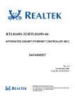
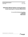
FIGURE 1-1 illustrates a generalized configuration showing how PCI devices are
interfaced to UltraSPARC-IIi using APB. This illustration shows the UltraSPARC-IIi
cache, DRAM, and PCI interfaces and the APB primary and secondary busses.
1. All references to the PCI specification are to PCI Local Bus Specification Revision 2.1—see Bibliography.
1
UltraSPARC-IIi
E-Cache
72
External
Cache Unit
DRAM
Control
72
DRAM
PCI Subsystem
32 bits at 33 or
66MHz; 3.3 V
Advanced PCI Bridge (APB)
PCI
Agents
1, 2
32 at 33 MHz
5 V Tolerant
32 at 33 MHz
5 V Tolerant
PCI
Agents
1, 2, 3, 4
PCI
Agents
1, 2, 3, 4
FIGURE 1-1
PCI Connectivity in an UltraSPARC-IIi System
1.2
Summary Features Description
1.2.1
Compatibility
APB is compatible with version 2.1 of the PCI Local Bus Specification with exceptions
listed in Section 1.2.6, “Exceptions to PCI Compatibility.” It is compatible with
version 1.0 of the PCI Bridge Specification 1, also subject to the exceptions listed in
Section 1.2.6.
1. All references to the PCI Bridge Specification are to the PCI to PCI Bridge Specification, version 1—see Bibliography.
2
Advanced PCI Bridge (APB) User’s Manual • November 1997
1.2.2
Voltage Interface
APB can deal with 3.3 V or 5 V PCI devices, giving it a wide range of application. In
particular, it can interface the UltraSPARC-IIi processor with 5 V devices on either
secondary bus.
1.2.3
Bus Features
■
PCI revision 2.1 compatible
■
DMA uses 32 or 64-bit memory addressing
■
PIO uses 32-bit memory addressing
■
PIO uses 24-bit I/O addressing
■
Accepts Fast Back-to-back Transactions as a target
■
Uses medium decode timing
■
Interrupt Acknowledge transaction supported
■
APB can be used to generate interrupt-acknowledge transactions (INT ACK
cycles), allowing standard PCI-to-ISA (“south“) bridges to be used with CPU/
host bridge combinations that are not able to generate INT ACKs
■
APB routes INT ACK cycles received on the primary bus to either secondary bus,
allowing standard south bridges to exist on the secondary bus instead of the
primary bus
■
■
PCI interrupts do not route through APB
APB is organized to implement two PCI to PCI bridge functions
■
PCI optional features not implemented:
■
Non-linear addressing modes
LOCK# pin
■
Clock stop protocol
■
Cache support pins
■
Does not generate Fast Back-to-Back cycles as a master
■
Does not subtractive decode
■
Memory Write and Invalidate transactions are treated as Memory Write
■
DOS Compatibility features
■
Does not step addresses or data
■
VGA support
Little-endian to the bus and internal configuration space
Errors resulting in assertion of SERR# are logged
■
Arbitration
■
■
■
■
■
Two on chip programmable arbiters, one for each secondary PCI interface; each
one handles up to 4 secondary bus masters
External arbiters for secondary PCI busses are allowed
Chapter 1
APB Features
3
1.2.4
1.2.5
Data Flow Control Features
■
Primary and secondary PCI interfaces can run concurrently
■
Deadlock detection and recovery; the recovery feature uses a retry counter
■
Does not enforce 16-clock initial target latency; this improves performance when
peer-to-peer communication is not present. However, Target Latency Timers can
limit wait states inserted by APB as a target
■
Master Retry Counters to limit the number of times APB attempts a transaction
■
Prefetching for some memory read commands—prefetching algorithm can be
adjusted for DMA operation
■
Boot Mode enables APB at reset. This feature allows devices on secondary PCI
bus B to incorporate boot PROMs
■
Target retry limit counters balance PIO transactions against DMA transactions
■
PCI ordering rules are enforced to enhance performance
Read/Write and Data Buffering
The APB allows PIO or DMA operations between a primary PCI bus that can run at
up to 66 MHz and either of two secondary PCI busses running at up to 33 MHz.
APB cannot preside over direct transactions between the secondary busses. Between
each secondary bus and the primary bus are two 72-byte FIFOs—one for PIO and
one for DMA. Each FIFO handles addresses, data, commands, and byte-enables.
1.2.6
Exceptions to PCI Compatibility
The APB does not meet the PCI specification in the following cases.
■
■
4
16 clock initial and 8 clock subsequent TRDY# latency are not always met. For
read cycles, TRDY# latency depends on the speed of the destination bus target
and the clock mode. In general, if the destination bus target does not insert wait
states and the busses are idle when a transaction begins, the latency guideline are
met.
Eight- clock initial IRDY# latency is not always met. For read cycles, IRDY#
latency depends on the clock mode, the number of wait states inserted by the
destination bus target, and the number of wait states inserted by the originating
bus master. In general, if the destination bus target does not insert wait states and
the busses are idle when a transaction begins, the latency guideline are met. For
write cycles, the latency depends on the clock mode and the number of wait states
inserted by the originating bus master. If the originating bus master inserts no
wait states, the latency guideline is met.
Advanced PCI Bridge (APB) User’s Manual • November 1997
■
■
■
■
■
■
The Base and Limit registers defined by the PCI Bridge Specification are not
implemented.
The Primary Master Latency Timer and Secondary Master Latency Timer registers
are initialized to 0x28 instead of 0x00.
I/O Write and Configuration Write transactions are posted.
The Memory Read Multiple command prefetches less than a cache line.
PCI Ordering rules are not followed. While all transactions originating on a
particular bus are ordered, there is no ordering between busses. In particular, a
read does not “pull out” any posted writes in the opposite direction. This implies
that the producer-consumer model is not valid. See Appendix E, p.260 of the PCI
Local Bus Specification, Revision 2.1 for more information about ordering rules.
Memory Write and Invalidate (MWI) commands are treated as Memory Write
commands:
■
■
■
■
APB does not guarantee that all byte enables are asserted, but passes on the
byte enables generated by the originating bus master.
APB can disconnect a MWI command on a data phase that is not a cacheline
boundary (Note: as APB is not a cacheable agent, this is not a PCI specification
violation).
If a MWI is disconnected by the target, APB continues the transaction with the
MWI command instead of the Memory Write command.
APB does not implement the special provisions for Master Latency timer
expiration during MWI commands (p.65 of the PCI specification).
■
The Master Latency Timers, when programmed to 0, are disabled.
■
Function 0 and function 1 share some configuration registers.
■
The timing specification for setup time, Tsu is relaxed from 3 ns to 5 ns on the
primary bus when it is run at 66 MHz.
■
Output slew rates on the primary bus exceed PCI specifications.
Chapter 1
APB Features
5
6
Advanced PCI Bridge (APB) User’s Manual • November 1997
CHAPTER
2
Architectural Overview
Primary Interface to UlltraSPARC-IIi
66 MHz, 3.3 V, 32 bits
Primary Interface
Address Decoder
Master
FSM
(DMA)
Target
FSM
(PIO)
Configuration
Registers
PIO-A
FIFO
72-byte
DMA-A
FIFO
72-byte
DMA-B
FIFO
72-byte
PIO-B
FIFO
72-byte
(PIO)
(DMA)
(DMA)
(PIO)
Secondary Interface
Address Decoder
Arbiter
A
Master
FSM
(PIO)
Target
FSM
(DMA)
Secondary Interface, PCI A
33 MHz, 3.3 V, 32 bits
Secondary Interface, PCI A
33 MHz, 3.3 V/5 V tolerant, 32 bit
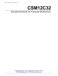
FIGURE 2-1
Secondary Interface
Address Decoder
Target
FSM
(DMA)
Arbiter
B
Master
FSM
(PIO)
Secondary Interface, PCI B
33 MHz, 3.3 V, 32 bits
Secondary Interface, PCI B
33 MHz, 3.3 V/5 V tolerant, 32 bit
Advanced PCI Bridge Data-paths and Modules
7
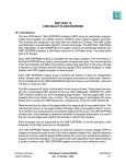
2.1
Functional Elements
FIGURE 2-1 shows the major data paths and blocks in APB.
The APB implements four data paths to accommodate either PIO or DMA
operations between the primary PCI bus at the CPU end and either of two secondary
PCI busses. APB cannot preside over transactions directly between either of the
secondary busses. These data paths are shown in TABLE 2-1.
TABLE 2-1
APB Data Paths
PCI Bus Initiating
Transaction (Master)
Target PCI Bus
Data Path
primary
A
PIO A
primary
B
PIO B
secondary A
primary
DMA A
secondary B
primary
DMA B
This arrangement provides for DMA or PIO transactions between either of two
secondary PCI busses that can run at up to 33 MHz, and a primary PCI bus that can
run at up to 66 MHz. PIO transactions are those initiated by the CPU to a target
device. DMA transactions are initiated by a device to main memory (which is
normally controlled by the CPU).
Each bus interface has a Finite State Machine (FSM) for the data path that it serves as
a master and one for the one where it acts as a target. These FSMs provide control
logic and are provided separately for each bus interface. Each data path contains a
FIFO buffer that can be written or read by either the primary or secondary side of
the data path. Each FIFO can store 72 bytes of address, data, as well as 18
command/byte enable groups.
The APB contains address decoders at each target bus interface. Bus arbiters within
APB resolve demands of bus-mastering devices at the secondary bus interfaces.
Configuration registers are only accessible from the primary bus interface and are
typically accessed by the CPU.
8
Advanced PCI Bridge (APB) User’s Manual • November 1997
2.2
Address Decoding
APB does not use the address decoding mechanisms described in the PCI Bridge
specification. For downstream transactions, the address space is divided into eight
segments. Each of these segments can be assigned to one of bus A, bus B, or no bus.
Transactions are then forwarded downstream if the three most significant bits (bits
31, 30, and 29 for memory transactions; bits 23, 22, and 21 for I/O transactions)
match a segment number that is assigned to bus A or bus B. Upstream memory
transactions use an inverse mapping; if the segment number formed from bits [31:29]
does not match a segment assigned to bus A or bus B, the transaction is forwarded
upstream. Upstream I/O transactions are never forwarded. Configuration
transactions in both directions are treated in accordance with the PCI bridge
specification. See Section 3.3, “Decoding and Address Spaces” on page 24 for more
information.
2.3
Data Buffering
APB has 72-byte data buffers for buffering of upstream and downstream
transactions. These buffers hold addresses, data, commands, and byte enables and
are used for both read and write transactions. Write transactions of all types—
memory, I/O, and configuration—are posted. Strict ordering of all transactions from
a particular bus to another bus (for example, primary to bus A) is maintained but no
ordering between busses is implied (for example, primary to bus A and bus A to
primary are not ordered). This lack of PCI ordering enhances performance by
reducing read latency. It does not cause problems in the Sun architectures because
such architectures do not require a producer-consumer model. See Section 3.2,
“Transaction Handling” on page 14 for more details.
Caution – The lack of ordering between PIO and DMA transactions involving the
same secondary bus is in violation of the PCI ordering rules.
Chapter 2
Architectural Overview
9
2.4
Error Support and Parity
Any error in a transaction, including master aborts, target aborts and parity errors, is
reported by APB in some fashion. In general, if the error can be reported in the
normal course of the transaction, it is. If this is not possible, SERR# is asserted.
Asynchronous fault status and address registers (AFSRs and AFARs) are provided
for each data path in the system to indicate the cause of SERR# assertion.
SERR# assertions on the secondary bus can be forwarded to the primary bus.
Address parity errors result in SERR# assertion, but the transaction is otherwise
handled normally.
All error handling functions are enabled/disabled by Command register bits in
accordance with the PCI and PCI Bridge specifications.
APB usually just passes along the data and parity received from one interface to the
other. There are some cases in which APB corrects or regenerates parity. See
Section 3.4, “Error Support” for details.
2.5
Deadlock Detection and Recovery
APB contains mechanisms to avoid and to detect deadlock conditions. Deadlocks are
avoided by retrying newly-received transactions that are known to cause deadlocks.
In some cases, this mechanism is not sufficient and the deadlock still occurs—for
example, when two transactions that deadlock each other arrive at the same time.
When a deadlock is detected, one of the deadlocked transactions is retried. See
Section 3.5, “Deadlocks and Performance” on page 38 for a full description of
deadlock handling.
2.6
PCI Bus Arbitration
APB contains a PCI bus arbiter for each of the two secondary PCI interfaces. Upon
exiting reset, the arbiter defaults to providing a fair arbitration scheme (round-robin)
to all secondary devices. Any device, including APB, can be given priority such that
it is granted the bus for every other transaction.
10
Advanced PCI Bridge (APB) User’s Manual • November 1997
Both arbiters can be independently disabled at reset, allowing external arbiters to be
used.
If there are no pending requests, APB parks at either the last granted agent or at the
bridge; there is a mode bit to select between these options.
See Section 3.6.1, “Arbitration” and Section 3.6.2, “Bus Parking” for more
information.
2.7
Reasons for PCI Non-Compliance
There are several points in which APB does not comply with the PCI 2.1
specification, as detailed in Section 1.2.6, “Exceptions to PCI Compatibility” on
page 4. These points can be classified by their reason for non-compliance, as
explained below.
Reset values and meanings of 0 in registers: These values differ from the PCI
specification for one of two reasons: to maintain compatibility with Sun’s U2P
bridge, or to allow the boot PROM to be located behind the bridge.
Base and limit registers: Base and limit registers only allow a single continuous
address range to be mapped to a secondary bus. The boot PROM is in high address
space (F000.0000) and must always be accessible. Solaris only allocates PIO address
space for devices with bit 31 cleared. For this reason, mapping registers are defined
to allow non-contiguous address mappings to the secondary bus.
66 Mhz setup timing: This timing is relaxed because it is difficult to attain while
including JTAG boundary scan and while using low-cost ASIC technologies.
Memory Write and Invalidate commands: UltraSparc-IIi neither generates nor
understands Memory Write and Invalidate Commands so support for their special
provisions is not necessary.
PCI ordering rules: APB is designed for principal use in a uni-processor system with
architectures and operating systems (for example, Sun4u and Solaris) that do not use
the Producer-Consumer Model of transaction ordering. Because of this, normal PCI
read vs. posted write ordering rules are not necessary. Removing them improves
performance as reads do not have to wait for opposing posted writes to complete.
Interrupt vs. DMA write ordering rules required by Sun’s architectures are
supported through the EMPTY/DRAIN interface.
Initial TRDY#/IRDY# latencies: There is a tradeoff between single-master/target read
latency and bandwidth utilization on the bus. The PCI specification requires targets
to retry prolonged transactions so that bandwidth may be used by other masters for
so-called “peer-to-peer” data transfers. The master that is retried incurs additional
latency in completing the read compared with what it would have incurred were it
Chapter 2
Architectural Overview
11
not retried (for example, it must rearbitrate and send the address again before
getting data). In the absence of peer-to-peer transactions, this process causes an
overall performance loss. APB is designed for operating systems that do not usually
generate peer-to-peer transactions in the I/O subsystem (for example, Solaris) so
APB ignores the initial latency restrictions, allowing higher performance in its
targeted systems.
UPA64S
Address
+ Control
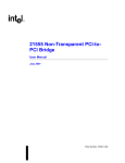
2 APB ICs can support
up to 16 PCI devices
6.4 G-bit/s
performance
PCI Slots
33 MHz/3.3 V; 5 V tolerant
UPA64S
Port
PCI
ATM
SCSI
32
T1/E1
RIC
I/O
Advanced PCI
Bridge (APB)
UltraSPARC-IIi
and L2 Cache
33 MHz/3.3 V; 5 V tolerant
32
10/100 Mb
Ethernet
MEMDATA
(64+ECC)
I/O
32
66 MHz/3.3 V
Transceivers
1 MB
Boot
PROM
Super I/O
8 kB TOD/
NVRAM
MEMADDR
+ Control
Memory Data
(128 + 16 ECC)
@37.5 MHz
10/100
Transceiver
Memory DIMMs
PCI Slots
I/O
PCI
Floppy I/F
Port
EIDE
Serial A/B
Mll
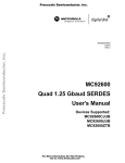
FIGURE 2-2
12
TP
System Implementation Example Using APB
Advanced PCI Bridge (APB) User’s Manual • November 1997
K/B Controller
CHAPTER
3
Functional Description
3.1
PCI Commands
lists the commands APB can generate and its response
to all commands as a target.
TABLE 3-1
TABLE 3-1
PCI Command Generation and Response
Command
C/BE#
APB
Generates?
APB Response
Interrupt Acknowledge
0000
Yes - sec
Ignored on Secondary busses
Special Cycle
0001
Yes
Special Cycles do not cross the bridge;
ignored
I/O Read
0010
Yes - sec
Ignored on Secondary busses; nonprefetched read on primary bus
I/O Write
0011
Yes - sec
Ignored on Secondary busses
Reserved
0100
No
Ignored
Reserved
0101
No
Ignored
Memory Read
0110
Yes
Perform non-prefetched read (PIO)
Perform 64 byte prefetched read (DMA)
Memory Write
0111
Yes
Perform write access
Reserved
1000
No
Ignored
Reserved
1001
No
Ignored
Configuration Read
1010
Yes - sec
Ignored on Secondary busses
13
TABLE 3-1
PCI Command Generation and Response (Continued)
Command
C/BE#
APB
Generates?
Configuration Write
1011
Yes
Ignored on Secondary busses (except to
generate special cycles or Type-1 to Type-1
Configuration Writes)
Memory Read Multiple
1100
Yes
Perform 8 byte prefetched read (PIO).
Perform 64 byte prefetched read (DMA)
Dual Address Cycle
1101
Yes - prim
Ignored on Primary bus
Memory Read Line
1110
Yes
Perform 64 byte prefetched read (PIO)
Perform 64 byte prefetched read (DMA)
Memory Write &
Invalidate
1111
Yes
3.2
Transaction Handling
3.2.1
Write Transactions
APB Response
Equivalent to Memory Write command
All write transactions occur in a decoupled fashion on the initiating interface and the
target interface of APB; that is, all write transactions (including I/O writes and
configuration writes) are posted. When a write transaction is received, decoded, and
accepted, APB checks the status of the FIFO for the appropriate data path. If the
FIFO is full or almost full (that is, the FIFO contains 68 or 72 bytes of valid addresses
or data), then Retry is signalled to the originating master. This Retry occurs to
prevent a deadlock condition. APB also signals Retry for write transactions on the
secondary interfaces when the DRAIN signal is asserted. If Retry is not immediately
asserted, the address and command are placed into the FIFO.
APB does not insert wait states (as a target) into write transactions. As data is
received, it is posted in the FIFO. APB disconnects the transaction if the FIFO
becomes full or almost full. This prevents a deadlock condition when two APBs are
used in a system.
APB signals disconnect with the first data phase for writes using non-linear burst
mode or writes to configuration space.
The write transaction may begin on the destination bus as soon as the transaction’s
address and command have been placed in the FIFO—provided that APB’s
destination bus master unit has been granted the bus, the bus is idle, and no
transaction is ahead of it in the FIFO. If the destination bus master unit has not yet
14
Advanced PCI Bridge (APB) User’s Manual • November 1997
been granted the bus, APB requests the bus as soon as the transaction has been
decoded and accepted. Once the bus is granted and idle, the transaction begins on
the destination bus—see timing diagrams of FIGURE 3-1 and FIGURE 3-2. Generally,
APB does not insert wait states into the transaction as a master. It can, however,
insert wait states if the transaction is still in progress on the originating bus and
APB’s master unit manages to drain the FIFO, either because of wait states inserted
by the original master, or differences in clock frequency. In these cases, APB may
prematurely terminate the transaction on the destination bus and continue with the
transaction once more data arrives. Also, APB’s master units break transactions on
1K boundaries and complete these transactions as new ones.
If APB receives a Disconnect or Retry on the destination bus, it attempts to continue
the transaction by requesting the bus again. When APB receives a Retry, a counter is
incremented and the Master Retry Limit Register for the appropriate data path is
checked. If the count equals the retry limit (and the limit is not 0), APB stops
retrying the transaction and clears it from the FIFO. If SERR# is enabled, it asserts
SERR#, and logs the status and address into the AFSR/AFAR registers for the data
path. The counter is cleared when a transaction is terminated in any way other than
Retry. There are individual Master Retry counters and Limit Registers for each data
path.
APB expects addresses to use linear burst ordering and is able to enforce this for
memory writes. The PCI specification does not define the burst ordering for
configuration and I/O writes. APB tries to impose a linear burst ordering on these
transactions. If a master bursts I/O or configuration writes through APB with a nonlinear burst ordering, the receiving target must not signal Disconnect (although
Retry is acceptable) or the continuing address will be incorrect.
Caution – The PCI specification states that I/O and Configuration writes cannot be
posted; in this respect, APB does not comply with the specification.
Chapter 3
Functional Description
15
clk
frame#
c/be#
Comm
BE1
BE2
ad
Addr.
Data1
Data2.
irdy#
trdy#
devsel#
clk_33
a_frame#
a_c/be#
a_ad
Comm
BE1
BE2
Addr
Data1
Data2
a_irdy#
a_trdy#
a_devsel#
a_req[0]#
a_gnt[0]#
FIGURE 3-1
16
Best Case PIO Write Timing
Advanced PCI Bridge (APB) User’s Manual • November 1997
clk
frame#
c/be#
Comm.
ad
BE1
Addr
BE2
Data1
Data2
irdy#
trdy#
devsel#
req#
gnt#
clk_33
a_frame#
a_c/be#
Comm
BE1
BE2
a_ad
Addr
Data 1
Data2
a_irdy#
a_trdy#
a_devsel#
FIGURE 3-2
3.2.2
Best Case DMA Write Timing
Read transactions
Read transactions are somewhat more complicated than write transactions. When a
read transaction is received, decoded, and accepted, APB checks the status of the
FIFO for the appropriate data path. If the FIFO is full or almost full (that is, the FIFO
contains 68 or 72 bytes of valid addresses or data), Retry is signalled to the
originating master. This performance optimization prevents the transaction from
occupying the bus when the FIFO is far from empty. APB also signals Retry for read
transactions when a deadlock condition is detected (see Section 3.5, “Deadlocks and
Performance” on page 38 for more details). If Retry is not immediately asserted, the
address and command are placed into the FIFO.
Chapter 3
Functional Description
17
APB inserts wait states into the first data phase as a target. It may also insert wait
states into subsequent data phases, depending on clock ratios and wait states
inserted by the destination target. A Retry may still be signalled after wait states in
the first data phase if a deadlock condition occurs.
The read transaction may begin on the destination bus as soon as the transaction’s
address and command have been placed in the FIFO, provided that APB’s
destination bus master unit has been granted the bus, the bus is idle, and no
transaction is ahead of it in the FIFO. If APBs destination bus master unit has not yet
been granted the bus, APB requests the bus as soon as the transaction has been
decoded and accepted. Once the bus is granted and idle, the transaction begins on
the destination bus.
At this point, exact read transaction handling depends on the prefetchability of the
transaction. Prefetchability and prefetch length are determined by a combination of
command type, direction through APB, and the USE_PIO_PREF bits of the Secondary
Control register as shown in TABLE 3-2.
TABLE 3-2
Prefetchability
Direction
Command
USE_PIO_PREF
Prefetchable
PIO
Memory Read
--
No
PIO
Memory Read Line
--
64 bytes
PIO
Memory Read Multiple
--
8 bytes
PIO
I/O Read
--
No
PIO
Configuration Read
--
No
PIO
Interrupt Acknowledge
--
No
DMA
Memory Read
0
64 bytes
DMA
Memory Read
1
No
DMA
Memory Read Line
0
64 bytes
DMA
Memory Read Line
1
64 bytes
DMA
Memory Read Multiple
0
64 bytes
DMA
Memory Read Multiple
1
8 bytes
DMA
I/O Read
--
Not accepted
DMA
Configuration Read
--
Not accepted
A prefetchable transaction implies that there are no side-effects to the read. APB can
attempt to read up to its prefetch limit without inserting wait states as a master. All
byte enables are asserted. Note that the prefetch limit is not a count of how many
bytes are transferred; rather, it is an indication of alignment. For example, a 64 byte
prefetch is terminated when the address reaches 0b...1111xx, regardless of how many
18
Advanced PCI Bridge (APB) User’s Manual • November 1997
bytes are actually transferred. A Disconnect is signalled to the originating master at
the end of the actually prefetched burst (This implies that all prefetched read
transactions are terminated on, at most, 64 byte boundaries). See the timing
diagrams for prefetched reads of FIGURE 3-4 and FIGURE 3-6.
Note that this prefetch buffer is not a “true” prefetch buffer because it is
automatically cleared after every transaction.
Caution – As prefetchable reads assert all byte enables and can read locations
beyond those desired, it is essential that a prefetchable read never be used in a
portion of address space that has side effects.
Non-prefetchable reads must wait for byte enables and FRAME# from the
originating master in order to proceed to a new data phase. This implies that the
following sequence of events happens for every data phase:
1. Destination target drives data and asserts TRDY#.
2. APB asserts TRDY# on the originating bus and drives data.
3. Once IRDY# and TRDY# are asserted on the originating bus (completing
originating data phase), APB asserts IRDY# on the destination bus, thus
completing the data phase.
4. If FRAME# is deasserted with IRDY# assertion on the originating bus, APB
deasserts FRAME# with IRDY# assertion on the destination bus. See the timing
diagrams of FIGURE 3-3 and FIGURE 3-5.
In some clock modes and directions, additional clocks of delay are added to allow
parity to be correctly propagated. Also, the parity received is modified in the
prefetched case to correct for the difference in byte enables between the originating
and the destination bus. This is done in such a way as to allow a parity error to be
propagated to the originating bus.
For both prefetchable and non-prefetchable reads, APB asserts TRDY# on the
originating bus whenever data becomes available and parity will be available at the
next clock.
Caution – APB does not obey the PCI ordering rules. In particular, reads do not
“pull out” any posted writes in the opposite direction.
If APB receives a Disconnect or Retry on the destination bus for either prefetchable
or non-prefetchable reads, it signals Disconnect or Retry on the originating bus at the
data phase at which it received the Disconnect or Retry on the destination bus. APB
does not try to continue or retry the transaction; this action is up to the originating
master.
Chapter 3
Functional Description
19
APB signals disconnect with the first data phase for reads to APB’s internal
configuration space. Non-linear bursts, burst Type 1 Configuration Reads or burst I/
O reads are possible through APB, as the final target is assumed to understand the
burst ordering.
clk
frame#
c/be#
ad
BE1
BE2
Addr
Data1
irdy#
trdy#
devsel#
clk_33
a_frame#
a_c/be#
a_ad
Comm
Addr
BE1
Data 1
a_irdy#
a_trdy#
a_devsel#
a_req[0]#
a_gnt[0]#
FIGURE 3-3
20
Best Case PIO Non-prefetchable Read Timing
Advanced PCI Bridge (APB) User’s Manual • November 1997
BE2
Data2
Data2
clk
frame#
c/be#
ad
Comm
BE1
BE2
Addr
Data1 Data2
irdy#
trdy#
devsel#
clk_33
a_frame#
a_c/be#
Comm
a_ad
Addr
0
Data 1
0
0
0
Data2
Data3
Data4
a_irdy#
a_trdy#
a_devsel#
a_req[0]#
a_gnt[0]#
FIGURE 3-4
PIO Prefetchable Read Timing
Chapter 3
Functional Description
21
clk
frame#
c/be#
BE1
ad
Addr
BE2.
Data1
Data2
irdy#
trdy#
devsel#
req#
gnt#
clk_33
a_frame#
a_c/be#
a_ad
Comm
BE1
Addr
a_irdy#
a_trdy#
a_devsel#
FIGURE 3-5
22
DMA Nonprefetchable Read Timing
Advanced PCI Bridge (APB) User’s Manual • November 1997
BE2
Data 1
Data2
clk
frame#
c/be#
Comm
ad
Addr
0
Data1. D2
D3
D4 D5
D6
D7
D8
irdy#
trdy#
devsel#
req#
gnt#
clk_33
a_frame#
a_c/be#
a_ad
Comm
BE1
Addr
BE2
Data 1
Data2
a_irdy#
a_trdy#
a_devsel#
FIGURE 3-6
DMA Prefetchable Read Timing
Chapter 3
Functional Description
23
3.3
Decoding and Address Spaces
3.3.1
Decoding
All APB target units use Medium decode timing for most transactions. In other
words, addresses and commands are latched into APB during the address phase. In
the clock after the address phase, APB decodes the transaction. If the transaction is
accepted, APB asserts DEVSEL# at the next clock edge. Configuration transactions,
however, require one additional clock for decoding.
clk
frame#
c/be#
ad
Comm
Addr
BE1
Data1
irdy#
trdy#
devsel#
FIGURE 3-7
3.3.2
Medium
DEVSEL Timing Diagram
Configuration Address Space and Transactions
The PCI configuration space is 16 MB and is accessed through PCI Configuration
transactions (The 16 MB is the result of multiplying 256 busses * 32 devices/bus * 8
functions/device * 256 bytes/function). Type 0 Configuration transactions address
devices on the bus upon which the transaction occurs. These transactions carry
function numbers and register numbers in the their addresses. Type 1 Configuration
transactions address devices on a bus other than the one upon which the transaction
occurs. These transactions carry bus numbers, device numbers, function numbers,
and register numbers in their addresses. Type 1 Configuration transactions must
cross a PCI to PCI bridge before they become Type 0 Configuration transactions.
24
Advanced PCI Bridge (APB) User’s Manual • November 1997
Type 0 and Type 1 Configuration transactions are distinguished by the value of
address bits AD[1:0]. Type 1 Configuration transactions can be forwarded by APB to
any level in the PCI bus hierarchy. Ultimately a bridge converts a type 1 transaction
to a type 0 transaction to configure devices connected to its secondary interface. See
the PCI specification for more information.
3.3.2.1
Type 0 Configuration Command
APB is selected by a PCI Configuration command on the primary bus if all of the
following conditions are true during the address phase of the transaction.
■
■
■
■
APB’s IDSEL pin is asserted
the bus command indicates a configuration read or write
the AD[1:0] bits are 00
AD[10:8] equal 0 or 1
AD[7:2] select a DWORD register in the 256 byte configuration address space for
each function. APB never responds to a Type 0 Configuration command on a
secondary bus. Type 0 Configuration commands on the primary bus are
disconnected with the first data phase.
clk
frame#
c/be#
ad
Comm
BE1
Addr
Data1
irdy#
trdy#
stop#
devsel#
FIGURE 3-8
Slow
Type 0 Configuration Read Timing
Chapter 3
Functional Description
25
clk
frame#
c/be#
Comm
BE1
ad
Addr
Data1
irdy#
trdy#
stop#
devsel#
Slow
Type 0 Configuration Write Timing
FIGURE 3-9
31
11 10
Function
Number
2Device Number (Only one ‘1’)
FIGURE 3-10
3.3.2.2
8 7
2 1 0
Register
Number
0 1
Type 0 Configuration Transaction Address
Type 1 Configuration command (primary bus)
Type 1 Configuration commands are ignored by the primary interface when the bus
number specified by address bits AD[23:16] does not fall within the range of bus
numbers specified by the secondary bus (inclusive), and subordinate bus (inclusive)
numbers in APB’s configuration registers for both bus A and bus B.
31
24 23
Reserved
FIGURE 3-11
26
16 15
Bus Number
11 10
Device
Number
Type 1 Configuration Transaction Address
Advanced PCI Bridge (APB) User’s Manual • November 1997
Function
Number
8 7
2 1 0
Register
Number
0 1
3.3.2.3
Type 1 to Type 0 Conversion
If the bus number of a type 1 command matches one of APB’s secondary bus
numbers APB responds to the configuration cycle and generates a PCI type 0
configuration command on the corresponding secondary PCI interface ( APB
modifies AD[1:0] to be 00). In this case a device connected to the bridge’s secondary
interface is the target of the PCI configuration command. Bits [31:11] are modified,
making only one bit a ’1’ to select the device as specified in bits [15:11]. The mapping
is the following:
For device number x, AD[x+11] is asserted.
For instance, Bit 12 is a 1 for device 1, bit 13 for device 2 etc. Address bits AD[10:2]
from the type 1 configuration command are passed unmodified. If a device number
greater than 20 is used, no AD[31:11] bit is asserted.
3.3.2.4
Type 1 to Special Cycle conversion—Secondary Bus
APB converts a type 1 configuration write transaction received on its primary
interface to a special cycle transaction on a secondary interface provided the
following conditions are met.
■
■
■
■
the
the
the
the
device number is all ones (AD[15:11] = 11111)
function number is all ones (AD[10:8] = 111)
register number is all zeros (AD[7:2] = 000000)
bus number matches one of the secondary bus numbers
The address is passed unmodified, but is ignored by PCI devices. The data for the
special cycle on the secondary interface is the write data from the type 1
configuration command on the primary interface. Type 1 configuration transaction
that specify conversion (by APB) to a special cycle are restricted to a data burst
length of 1.
3.3.2.5
Type 1 to Type 1 Forwarding
If the bus number of a type 1 configuration command is in the range of bus numbers
between the secondary bus number (exclusive) and the subordinate bus number
(inclusive) for either bus A or bus B, APB forwards the type 1 command unmodified
from the primary interface to the secondary interface.
3.3.2.6
Type 1 Configuration command (secondary bus)
All Type 1 configuration reads are ignored on the secondary interface.
Chapter 3
Functional Description
27
Type 1 configuration write commands are ignored on the secondary interface except
for the two cases below.
3.3.2.7
Type 1 to Special Cycle Conversion—Primary Bus
APB converts Type 1 Configuration writes on a secondary bus to Special Cycles on
the primary bus under the following conditions:
■
■
■
■
the
the
the
the
device number is all ones (AD[15:11] = 11111)
function number is all ones (AD[10:8] = 111)
register number is all zeros (AD[7:2] = 000000)
bus number matches the primary bus number
The address is passed unmodified, but is ignored by PCI devices. The data for the
special cycle on the primary interface is the write data from the type 1 configuration
command on the secondary interface. Type 1 configuration cycles that specify
conversion (by APB) to a special cycle are restricted to a data burst length of 1.
3.3.2.8
Type 1 to Type 1 Forwarding
APB forwards Type 1 Configuration writes to the primary bus under the following
conditions:
■
■
■
■
■
the device number is all ones (AD[15:11] = 11111)
the function number is all ones (AD[10:8] = 111)
the register number is all zeros (AD[7:2] = 000000)
the bus number does not match the primary bus number
the bus number is not in the range of bus numbers between the secondary bus
number (exclusive) and the subordinate bus number (inclusive) for the interface
Forwarded transactions are not modified.
28
Advanced PCI Bridge (APB) User’s Manual • November 1997
3.3.3
Memory address space
APB does not implement the Base and Limit registers in the PCI Bridge
specification. Instead, PCI primary bus memory space is divided into eight segments
as follows:
TABLE 3-3
PCI Memory Address Segments
Segment Number
PCI Memory
Address Range
0
0x0000.0000–
0x1FFF.FFFF
1
0x2000.0000–
0x3FFF.FFFF
2
0x4000.0000–
0x5FFF.FFFF
3
0x6000.0000–
0x7FFF.FFFF
4
0x8000.0000–
0x9FFF.FFFF
5
0xA000.000–
0xBFFF.FFFF
6
0xC000.000–
0xDFFF.FFFF
7
0xE000.0000–
0xFFFF.FFFF
Each segment can be individually programmed through the Memory Address Map
Registers. If bit number x of an address map register is set, then segment x is
assigned to that bus. For example, if the values of the address registers are
Memory Address Map A: 0b00000011
Memory Address Map B: 0b11110000
all PIO memory accesses with bit AD[31:29] equal to 0b1xx are directed to bus B and
all PIO memory accesses with bit AD[31:29] equal to 0b00x are directed to bus A.
PIO Memory accesses with AD[31:29] equal to 0b01x do not cause a response by
APB.
Caution – A segment must not be mapped to both busses. In other words, (Memory
Address Map A & Memory Address Map B) == 0 must be true at all times. It is the
responsibility of configuration software to enforce this relationship.
Chapter 3
Functional Description
29
DMA memory transactions use an inverse decoding mechanism for single address
cycles. If the address falls in a segment not mapped to either secondary bus, the
transaction is accepted and passed to the primary bus. For dual address cycles, the
transaction is accepted and passed to the primary bus if AD[63:50] = 0x3FFF (64-bit
addressing). Bits 36:29 are not checked.
If the BOOT pin is tied high at reset, Memory Address Map B is set to 0xFF. This
configuration allows execution from a boot PROM on bus B. APB does not support a
boot PROM on bus A.
Note – If the Memory Response Enable bit in the Primary Command Register is not
set, no PIO memory transactions are accepted. Similarly, if the Master Enable bit in
the Primary Command Register is not set, no DMA memory transactions are
accepted.
3.3.4
I/O address space
APB supports 24-bit addressing for I/O using separate Address Map registers from
those used for memory addressing. Address bits [31:24] must be 0. This gives the
following mapping of segments to I/O addresses.
TABLE 3-4
Segment
Number
30
PCI I/O Address Segments
PCI I/O
Address Range
0
0x0000.0000–
0x001F.FFFF
1
0x0020.0000–
0x003F.FFFF
2
0x0040.0000–
0x005F.FFFF
3
0x0060.0000–
0x007F.FFFF
4
0x0080.0000–
0x009F.FFFF
5
0x00A0.0000–
0x00BF.FFFF
6
0x00C0.0000–
0x00DF.FFFF
7
0x00E0.0000–
0x00FF.FFFF
Advanced PCI Bridge (APB) User’s Manual • November 1997
APB performs a full 32 bit decode of the I/O address as required by the PCI
specification. These mappings only apply to PIO; APB accepts no DMA I/O
transactions.
Note also that if the I/O Response Enable bit in the Primary Command Register is
not set, APB accepts no PIO I/O transactions.
Caution – A segment must not be mapped to both busses. In other words, (I/O
Address Map A & I/O Address Map B) == 0 must be true at all times. It is the
responsibility of configuration software to enforce this relationship.
3.3.5
Decoding Example: One APB in an
UltraSPARC-IIi-based System
This section gives a sample address mapping for a one- APB UltraSPARC-IIi-based
system. Half of the address space is allocated to the primary bus and the remainder
is equally divided between the two secondary busses. The PROM is located on
APB’s bus B. Bus A is numbered bus one, Bus B is numbered bus 2. The primary bus
is bus 0.
The Address Map registers contain:
■
■
■
■
Memory Address Map A: 0b00000011
Memory Address Map B: 0b11000000
I/O Address Map A: 0b00110000
I/O Address Map B: 0b11000000
TABLE 3-5 shows the address ranges.
TABLE 3-5
Example Address Ranges
UltraSPARC-IIi
Physical Address
Range
Primary Bus AD
Range
Secondary Bus AD
Range
APB Configuration Space
0x1FE.0100.0800–
0x1FE.0100.09FF
0x0000.1000–
0x0000.11FF
n/a
Other Primary
Configuration Space
0x1FE.0100.1000–
0x1FE.0100.FFFF
0x0000.2000–
0x8000.07FF
n/a
Bus A Configuration Space
0x1FE.0101.0000–
0x1FE.0101.FFFF
0x0001.0001–
0x0001.FFFF
0x0000.0800–
0x8000.07FF
Bus B Configuration Space
0x1FE.0102.0000–
0x1FE.0102.FFFF
0x0002.0001–
0x0002.FFFF
0x0000.0800–
0x8000.07FF
Address Space
Chapter 3
Functional Description
31
TABLE 3-5
Example Address Ranges (Continued)
UltraSPARC-IIi
Physical Address
Range
Primary Bus AD
Range
Secondary Bus AD
Range
Bus A I/O Space
0x1FE.0280.0000–
0x1FE.02BF.FFFF
0x0080.0000–
0x00BF.FFFF
0x0080.0000–
0x00BF.FFFF
Primary Bus I/O Space
0x1FE.0200.0000–
0x1FE.027F.FFFF
0x0000.0000–
0x007F.FFFF
n/a
Bus B I/O Space
0x1FE.02C0.0000–
0x1FE.02FF.FFFF
0x00C0.0000–
0x00FF.FFFF
0x00C0.000–
0x00FF.FFFF
Bus A Memory Space
0x1FF.0000.0000–
0x1FF.3FFF.FFFF–
0x0000.0000–
0x3FFF.FFFF
0x0000.0000–
0x3FFF.FFFF
Primary Bus Memory Space
0x1FF.4000.0000–
0x1FF.BFFF.FFFF
0x4000.0000–
0xBFFF.FFFF
n/a
Bus B Memory Space
0x1FF.C000.0000–
0x1FF.FFFF.FFFF
0xC000.0000–
0xFFFF.FFFF
0xC000.0000–
0xFFFF.FFFF
PROM Space
0x1FF.F000.0000–
0x1FF.F1FF.FFFF
0xF000.0000–
0xF1FF.FFFF
0xF000.0000–
0xF1FF.FFFF
Address Space
3.3.6
Interrupt Acknowledge
APB is able to route Interrupt Acknowledge transactions received on the primary
bus to either of the secondary busses. Interrupt Acknowledge transactions received
on either of the secondary busses are ignored. If the (Secondary Control A/B).
ROUTE_INT_ACK bit is set, all Interrupt Acknowledge transactions are routed to
the corresponding bus. Do not set more than one ROUTE_INT_ACK bit.
If ROUTE_INT_ACK bits are not set, Interrupt Acknowledge transactions are routed
to secondary busses based on the address. The address is decoded as if the
transaction were an I/O transaction, using the I/O Address Map Registers.
However, an Interrupt Acknowledge transaction decoded to a particular bus is only
accepted by APB if the corresponding (Secondary Control A/B).MAP_INT_ACK bit
is set.
Caution – Do not set ROUTE_INT_ACK for more than one bus. Do not set
MAP_INT_ACK for any bus if ROUTE_INT_ACK is set on any bus.
If none of the ROUTE_INT_ACK bits or MAP_INT_ACK bits are set, APB does not
respond to any Interrupt Acknowledge transactions.
32
Advanced PCI Bridge (APB) User’s Manual • November 1997
APB can also generate Interrupt Acknowledge transactions. When register 0xB8 of
either function is read (through a Configuration Read transaction), an Interrupt
Acknowledge transaction is generated on the corresponding secondary bus. The
data returned by the final target is returned by APB to the originating master. The
address generated for the Interrupt Acknowledge transaction is undefined.
3.4
Error Support
APB adheres to the PCI Bridge specification in its treatment of error conditions by
attempting to propagate errors on the destination bus to the originating bus. If it
cannot do so it asserts SERR#. All error conditions are reported in some way if the
appropriate enable bits are set.
Errors that are reported by SERR# assertion cause status and address information to
be latched into the PIO/DMA AFSR/AFAR Registers. There are four sets of AFSR/
AFARs, one for each data path. Section 4.1.3.15, “PIO/DMA Asynchronous Fault
Registers A/B (0xE8/0xC8)” on page 65 describes the logging of errors into the
AFSR/AFARs.
TABLE 3-6 shows the bits that affect error reporting.
TABLE 3-6
Bits Affecting Error Reporting
Register
Name
Bit
Name
Function
0x004
Primary Control
8
SERR_EN
Enables SERR# assertion on
primary bus
0x004
Primary Control
6
PER
Enables PERR# on primary
bus
0x03E
Bridge Control A
5
Master abort
mode
Changes master abort
handling on PIO A and
DMA A data paths
0x03E
Bridge Control A
1
SERR# Enable
Enables translation of
SERR# on bus A to primary
SERR#
0x03E
Bridge Control A
0
PER
Enables PERR# on bus A
Chapter 3
Functional Description
33
TABLE 3-6
Bits Affecting Error Reporting (Continued)
Register
Name
Bit
Name
Function
0x13E
Bridge Control B
5
Master abort
mode
Changes master abort
handling on PIO B and DMA
B data paths
0x13E
Bridge Control B
1
SERR# Enable
Enables translation of
SERR# on bus B to primary
SERR#
0x13E
Bridge Control B
0
PER
Enables PERR# on bus B
Each of the error conditions is described in the following sections.
3.4.1
Address parity error
When APB detects an address parity error on the primary bus, it takes the action:
■
If (Primary Command).PER is set and (Primary Command).SERR_EN is set, it
■
Asserts primary SERR# one clock later
■
Sets (Primary Status).SSE
■
Reports the error in both PIO AFSR/AFARs
■
Sets (Primary Status).DPE
■
Decodes the transaction and proceeds normally
When APB detects an address parity error on a secondary bus, it takes the steps:
■
3.4.2
If (Bridge Control).PER is set and (Primary Command).SERR_EN is set, it
■
Asserts primary SERR# one clock later
■
Sets (Primary Status).SSE
■
Reports the error in the appropriate DMA AFSR/AFAR
■
Sets (Secondary Status).DPE
■
Decodes the transaction and proceeds normally
Write data parity error
When APB detects a parity error on the primary bus during a PIO write, it takes the
following steps:
■
If (Primary Command).PER is set
■
■
34
asserts PERR# on primary bus
Sets (Primary Status).DPE
Advanced PCI Bridge (APB) User’s Manual • November 1997
■
Continues transaction normally
When APB receives a PERR# assertion on the secondary bus during a PIO write, it
takes the following steps:
■
If (Bridge Control).PER is set
■
■
If (Primary Command).SERR_EN is set
■
■
sets (Secondary Status).DPD
asserts primary SERR# and logs error in the appropriate PIO AFSR/AFAR
Continues transaction normally
When APB detects a parity error on the secondary bus during a DMA write, it takes
steps:
■
If (Bridge Control).PER is set
■
asserts PERR# on secondary bus
■
Sets (Secondary Status).DPE
■
Continues transaction normally
When APB receives a PERR# assertion on the primary bus during a DMA write, it
takes these steps:
■
If (Primary Command).PER is set
■
3.4.3
sets (Primary Status).DPD
■
If (Primary Command).SERR_EN is set, asserts primary SERR# and logs error in
the appropriate DMA AFSR/AFAR
■
Continues transaction normally
Read data parity error
When APB detects a parity error on the secondary bus during a PIO read, it follows
the procedure:
■
If (Bridge Control).PER is set, APB
■
■
■
■
Asserts PERR# on the secondary bus
Sets (Secondary Status).DPD
Sets (Secondary Status).DPE
Continues transaction normally
When APB receives a PERR# assertion on the primary bus during a PIO read, it
follows the procedure:
■
Continues transaction normally
Chapter 3
Functional Description
35
When APB detects a parity error on the primary bus during a DMA read, it follows
the procedure:
■
If (Primary Command).PER is set:
■
■
■
■
Asserts PERR# on primary bus
Sets (Primary Status).DPD
Sets (Primary Status).DPE
Continues transaction normally
When APB receives a PERR# assertion on the secondary bus during a DMA read, it
takes steps:
■
3.4.4
Continues transaction normally
Master Aborts
When APB receives a Master Abort on the destination bus and the transaction is not
a special cycle it proceeds as follows.
■
The Received Master Abort (RMA) bit in the status register corresponding to the
destination bus is set
■
If the (Bridge Control).Master Abort Mode bit is set:
■
If the transaction is still continuing on the originating bus (for example, a read
or a very long write burst),
●
●
■
If the transaction is not continuing and (Primary Command).SERR_EN is set:
●
●
●
■
■
3.4.5
Signals Target Abort on the originating bus
Sets STA bit in the appropriate bus status register
Asserts SERR# on the primary interface
Sets (Primary Status).SSE
Logs error in appropriate AFSR/AFAR
Clears the transaction from the appropriate FIFO
If the (Bridge Control).Master Abort Mode bit is clear, then APB returns
0xFFFFFFFF to the originating master for reads, and silently drops writes
Target Aborts
When APB receives a Target Abort on the destination bus, it proceeds as follows.
■
■
36
The Received Target Abort (RTA) bit in the status register corresponding to the
destination bus is set
If the transaction is still continuing on the originating bus (for example, a read or
a very long write burst),
■
Signals Target Abort on the originating bus
Advanced PCI Bridge (APB) User’s Manual • November 1997
■
■
■
■
■
■
3.4.6
Sets STA bit in the appropriate bus status register
If the transaction is not continuing and (Primary Command).SERR_EN is set,
Asserts SERR# on the primary interface
Sets (Primary Status).SSE
Logs error in appropriate AFSR/AFAR
Clears transaction from the appropriate FIFO
Master Retry Limit
For all read transactions a Disconnect or Retry received by APB is returned to the
initiator of the transaction as a Disconnect or Retry.
For a write, if APB receives a Disconnect or Retry it attempts to retransmit the
remaining data. It maintains a count of how many times Retry is received and resets
this counter whenever data is successfully transferred or the transaction is Target or
Master Aborted. If the retry count reaches four times the value of the Master Retry
Limit register for the data path and the Master Retry Limit is non-zero, APB takes
these steps:
■
■
3.4.7
If (Primary Command).SERR_EN is set,
■
Asserts SERR# on the primary interface
■
Sets (Primary Status).SSE
■
Logs error in appropriate AFSR/AFAR
Clears transaction from the appropriate FIFO and ceases to retry the transaction
Secondary Interface SERR#
Whenever A/B_SERR# is asserted on the secondary interface, APB takes the action:
■
Sets (Secondary Status).RSE
■
If (Bridge Control).Serr# Enable is set, and (Primary Command).SERR_EN is set,
■
Asserts SERR# on the primary interface
■
Sets (Primary Status).SSE
Note – This case is the only one in which primary SERR# is asserted without
logging anything in the AFSR/AFAR.
Chapter 3
Functional Description
37
3.5
Deadlocks and Performance
Because APB connects to three concurrent busses, there is the possibility of resource
contention and deadlock. APB target units contain logic to deal with this problem.
The deadlock handling logic must satisfy four goals:
■
■
■
■
3.5.1
Correctness - All posted write data phases must eventually complete. No extra
posted write data phases or non-prefetched read data phases may occur
Deadlock-Free Operation - Deadlock situations must either be avoided or detected
and broken
Completion - The time that a transaction must wait from beginning on the
originating bus to beginning on the destination bus must be bounded
Performance - All of the above should be accomplished with as little latency as
possible and should conserve bus bandwidth
Deadlock Situations
APB can experience deadlocks because of contention on a PCI bus. The general case
is that the target/master unit pair for one data path wants to use the destination bus
while the target/master unit pair for the opposite data path wants to use the
originating bus of the first pair. For example, a PIO transaction to bus A could
deadlock with a DMA transaction from bus A. The two pairs must be opposites for
deadlock to be possible; that is, a PIO transaction to bus A cannot deadlock with a
DMA transaction from bus B.
Note that the targets are the important units here; a busy target unit indicates that
the bus is unavailable for use. If the opposing target units are both busy at the same
time, and neither one can finish its transaction, deadlock has occurred. For example,
a PIO read to bus A arrives at the same time as a DMA read from bus A. As a result,
the bus A target unit is busy dealing with the primary bus while the primary bus
target unit is busy dealing with bus A. The corresponding master units are unable to
begin their transactions so neither target unit can finish its transaction. Deadlock has
occurred.
There are three exact deadlock conditions:
Condition 1: DMA read against PIO read. This is the situation described above.
Neither master can gain control of the destination bus so neither target can proceed.
Condition 2: DMA read against PIO write (or DMA write against PIO read).
Deadlock only occurs in this case when the FIFO in the direction of the write
transaction becomes full. The writing target unit cannot proceed and the FIFO
38
Advanced PCI Bridge (APB) User’s Manual • November 1997
cannot be drained because the writing master unit cannot gain control of the
destination bus. The reading target unit cannot proceed because the reading master
unit cannot gain control of its bus.
Condition 3: DMA write against PIO write. Deadlock occurs when both FIFOs
involved become full. Neither target unit can proceed until its FIFO begins to drain,
but the FIFOs cannot drain until the master units gain control of their busses, which
cannot happen while the target units are busy.
Note again that in every one of these cases the two transactions must be on opposing
busses for deadlock to be possible.
There are also two deadlock cases involving multiple APBs:
Condition 2—with multiple APBs: DMA reads against PIO or DMA reads where
each read is preceded by a write. In this case the transactions pass in opposite
directions through two APBs and the writes fill up the FIFOs in the second APB that
each transaction passes through. If there is still posted write data in each
transaction’s first APB—but not enough to fill the first FIFO—and the reads arrive,
the reads can be in wait states on both busses without being able to proceed because
of the write data ahead of them. This is a special case of deadlock condition 2 in
which the busy target units are in different APBs.
Condition 3—with multiple APBs: DMA write against DMA write where
transactions originating on one secondary bus are destined for another secondary
bus. If two opposing write transactions—that is, the master of each transaction is on
the same bus as the target of the other transaction—occur, it is possible for both the
PIO and DMA FIFOs in both APBs to fill. This is a special case of deadlock condition
3, but in this case the deadlock occurs because both secondary target units are busy;
the primary target units may or may not be busy.
3.5.2
Deadlock handling
APB implements a distributed deadlock detection and recovery mechanism rather
than a centralized arbiter-based deadlock avoidance scheme. All deadlock detection
is localized to the target units, which communicate with each other. Deadlock
recovery is accomplished by retrying or disconnecting one or both of the deadlocked
target units. Each of the deadlock conditions described above is detected and
handled as follows:
■
■
DMA read against PIO read. While decoding a transaction, the target unit checks
the state of the opposing target unit. If that target unit is busy with an opposing
read transaction, Retry is signalled for the newly arrived transaction (the
transaction is still claimed). If opposing transactions arrive at the same time, the
transaction on the secondary bus is retried.
DMA read against PIO write (or DMA write against PIO read). If the write
transaction’s FIFO becomes full, the write transaction is disconnected.
Chapter 3
Functional Description
39
■
DMA write against PIO write. If a FIFO becomes full, the corresponding write
transaction is disconnected. If both become full simultaneously, then both are
disconnected.
Note that deadlock conditions 2 and 3 are handled in the same manner. This
handling of condition 3 cause Disconnects in some situations that are not yet true
deadlocks. This was done for ease of implementation, and may help performance by
making deadlock condition 3 much less likely to occur. It also effectively solves the
special multiple-APB deadlock 3 case without complicated logic.
The special multiple-APB case of deadlock condition 2 is not handled by APB. The
only way of handling this case is to set the Target Latency Timer register for each
data path to a non-zero value. This forces the read transactions off the bus after the
timer count has expired, allowing the writes to progress.
3.5.3
Completion guarantees
The above handling of deadlocks does not guarantee completion; it is conceivable
that a particularly unlucky transaction could be retried as long as there is opposing
traffic. Conditions 2 and 3 do not have completion problems; as long as no deadlock
occurs and the arbiters for all busses are fair, then the FIFO must drain partially at
some point, allowing the write transaction to continue. Condition 1, however, could
lead to “infinite” retries. To deal with this case, a Target Retry Limit register exists
for each data path.
Each time a target unit must signal Retry, it increments a counter. This counter is
cleared at any time that the target unit transfers data or signals target abort. If the
counter equals the Target Retry Limit for the data path, and the Target Retry Limit is
not 0, then the transaction is not Retried. Instead, the opposing read is Retried when
deadlock condition 1 is detected.
There are some unusual corner cases in which the retry counters for both of the
target units have reached their limits. In these cases, the PIO transaction is Retried.
When the DMA transaction has transferred data onto the originating bus, its counter
is cleared, so the PIO transaction will then be able to complete when it returns on the
primary bus.
Caution – Completion is only guaranteed if Target Retry Limit registers for all data
paths are not zero, Target Latency Timers for all data paths are zero, and Master
Retry Limit registers for all master units are zero.
40
Advanced PCI Bridge (APB) User’s Manual • November 1997
Also related to the completion guarantees is the method that the primary master
unit uses to select between Bus A and Bus B DMAs. The master usually alternates
between busses when both have outstanding transactions. If the master receives a
Retry or Disconnect for a posted write, it continues with that transaction instead of
going to the other bus.
There is a caveat to the completion guarantees: The completion guarantees do not
hold if a master bursts a write for an infinite amount of time. Once a DMA write
transaction is accepted on a secondary bus and is driven onto the primary bus, it is
allowed to continue forever unless the FIFO fills. DMA from the other secondary bus
will not proceed until all the write data completes or the write transaction master
aborts or target aborts. For best performance, DMA masters should not burst beyond
a few cache lines unless no DMA capable masters are present on the other secondary
bus.
3.5.4
Performance optimizations
The values of the Target Retry Limits have an effect on performance, in that they can
be used to balance the PIO against DMA mix. APB’s target units also contain two
more features for performance improvement and tuning.
First, when deadlock condition 1 occurs, the first deadlocked transaction to reach
APB is normally not retried. However, if there is a posted write ahead of the first
read to arrive, and there is no posted write ahead of the second read, then the first
read will be retried, allowing the second read transaction to proceed immediately.
Second, each data path also has a Target Latency Timer. This timer is used to limit
the number of wait states that the target can insert on the first data phase. A counter
is incremented for each wait state. If the counter reaches the timer value (this value
is non-zero) and the transaction has not begun on the destination bus, the
transaction is retried. This allows the originating bus to be used by other masters.
The transaction is completely cancelled inside APB; when it is received again, it is
treated as a new transaction (In other words, there are no Delayed Completion
semantics). Retries caused in this manner are added to the target retry counter, but
they are not prevented by the retry counter hitting the Target Retry Limit.
Note – The target retry counter saturates at the Target Retry Limit and does not
count beyond it.
Caution – Because the Retry caused by a target latency timeout is not prevented by
the target retry counter, if you set any non-zero value in the Target Latency Timer,
completion can no longer be guaranteed. Furthermore, it is possible to set the timer
to such a low value (≈8 for the primary bus) that no transactions can be completed.
Chapter 3
Functional Description
41
However, it may be necessary to set this timer to prevent the special multiple- APB
deadlock 2 case from occurring. If the timer is being set for this purpose alone, it
should be set to its maximum value.
3.6
Other Functionality
3.6.1
Arbitration
APB contains a PCI bus arbiter for each of the secondary PCI busses, but can also
work with external bus arbiters on these busses. The enabling or disabling of the
internal arbiters can be done separately through the PCI Control Register A/B
respectively through pull-ups or pull-downs on the a_GNT[3]# and b_GNT[3]# pins.
A pull-up on one of these pins enables the corresponding arbiter at reset, while a
pull-down disables the corresponding arbiter at reset. If the arbiter for bus x is
disabled, APB’s request and grant lines are x_REQ[0]# and x_GNT[0]#.
Caution – Because the arbiter enable/disable function controls whether x_GNT#
lines will be driven by APB, it is important to avoid both contention and floating or
multiple grants while enabling/disabling the arbiter through the PCI Control
Register. This applies also to the A_REQ[0]# and B_REQ[0]# signals.
Two arbitration schemes are implemented in APB on-chip PCI arbiters. The default
is fair arbitration where all enabled requests are serviced in round-robin fashion. The
second scheme (enabled by the ARB_PRIO and CPU_PRIO bits in the PCI Control
Register) gives higher priority to a specific request. This allows the device attached
to that request/grant pair to claim every other PCI transaction. The CPU_PRIO bit
will give APB the higher priority, while the ARB_PRIO bits give higher priority to
external request lines.
Caution – No more than one of the CPU_PRIO and ARB_PRIO bits must be set at
one time. Changing arbiter control or enable bits while requests or transactions are
outstanding on a secondary bus produces undefined results.
Note that all external request lines must be enabled by setting the appropriate (PCI
Control Register).ARB_EN bit before they are honored.
42
Advanced PCI Bridge (APB) User’s Manual • November 1997
3.6.2
Bus Parking
The ARB_PARK bit in the PCI Control Register causes the last x_GNT# to remain
asserted when no other requests are asserted. This state results in a two-clock
reduction in arbitration latency for bursts of transactions from the same device. If
this bit is not set, x_GNT# reverts to APB when no other requests are asserted.
Note – The internal arbiters must be enabled for APB’s bus parking to occur.
3.6.3
Interrupt Synchronization
As APB does not follow the normal PCI ordering rules, a mechanism is needed to
ensure that any posted write transactions from non-CPU masters on PCI have
completed before an interrupt is handled. In the normal PCI case, this result would
be achieved by reading a status register in the interrupting device. The ordering
rules would ensure that posted writes are flushed before returning the read data. In
APB’s case, the CPU asserts a DRAIN signal before handling the interrupt. While
this signal is asserted, APB retries all DMA writes. The CPU continues to assert
DRAIN until APB signals EMPTY. After seeing EMPTY, the CPU handles the
interrupt. EMPTY is asserted when the DMA FIFOs do not contain write data and
the primary master unit is not trying to continue a Retried or Disconnected write.
See the timing waveforms of FIGURE 3-12.
Chapter 3
Functional Description
43
clk
frame#
c/be#
BE1
ad
Addr
BE2
Data1 Data2
irdy#
trdy#
devsel#
req#
gnt#
empty
US-IIi INT US-IIi receives an interrupt.
drain
clk_33
a_frame#
a_c/be#
Write
BE1
BE2
Write
BE1
a_ad
Addr
Data 1
Data2
Addr
Data
a_irdy#
a_trdy#
a_stop#
a_devsel#
Write is retried because drain is asserted
FIGURE 3-12
Drain/Empty Protocol Timing
Note that the necessity of this synchronization may vary from system to system. The
situation is essentially a race between the interrupt handler/OS/application needing
write data at the end of the transfer and the hardware completing the write. For
multiple levels of bridges and very fast software, the problem is more severe. For
single levels of bridges and slow drivers, the hardware may “win” the race easily
and not require synchronization support. If this is the case, DRAIN can be grounded.
If APBs are connected hierarchically, the drain input to APBs higher in the hierarchy
must not be asserted unless all APBs below it are signalling empty. See FIGURE 3-13
on page 45.
44
Advanced PCI Bridge (APB) User’s Manual • November 1997
UltraSPARC-IIi
Drain Empty
PCI Bus
E
APB
D
PCI Bus
E
PCI Bus
APB
D
PCI Bus PCI Bus
An APB Drain input must only be asserted if lower APBs signal Empty
FIGURE 3-13
3.6.4
Control of Drain Inputs in an APB Hierarchy
Boot mode
If APB lies in the access path between the CPU and the boot PROM, its boot pin
must be tied high to make it emerge from reset accepting memory transactions. APB
comes out of reset enabled for memory transactions to the B bus only in the following
address range:
0x0000.0000 - 0xFFFF.FFFF
3.6.5
Reset
Primary bus reset is an input to APB. Reset assertion is asynchronous and
asynchronously tristates all output pins (except A_RST# and B_RST#). All internal
state machines and configuration registers are reset. RST# should be asserted for at
Chapter 3
Functional Description
45
least 12 clocks. If the clock does not pulse, all output pins (except A_RST# and
B_RST#) remain tristated, even after RST# deassertion. Reset deassertion is
synchronized internally to the primary bus clock. The first transaction should not
begin until at least 12 clocks after RST# is deasserted. APB drives reset onto the
secondary busses whenever the primary bus is reset, or when the appropriate
(Bridge Control A/B).SEC_BUS_RST is set. When a secondary bus is reset through
the Bridge Control Register, APB drives zeros on all signals of that bus. The
secondary slave, master, and arbiter units are reset, as are all FIFOs connected to that
unit. No configuration registers are changed for a secondary bus reset through the
Bridge Control Register.
3.6.6
Clocking
APB can be run in 2:1 or 1:1 clock mode. The maximum primary bus frequency in
2:1 clock mode is 66 MHz; the maximum primary bus frequency in 1:1 clock mode is
33 MHz. The primary bus clock should be attached to the CLK input of APB. In 2:1
clock mode, the secondary bus clock is attached to the Clk_33 input. In 1:1 mode, the
Clk_33 input should be tied either high or low.
The secondary and primary bus clocks must be held closely in phase.
Note – The maximum skew between the primary bus clock input of APB and the
bus clock input of any device on a secondary bus must be less than 2 ns.
Internally, APB uses a PLL to remove insertion delay from the primary bus clock.
For frequencies above 33 MHz, the PLL must be enabled by driving PLLEN high. To
change clock frequency, RST# must be asserted and sufficient PLL lock time must be
allowed. For frequencies below 33 MHz, the PLL must be bypassed by tying PLLEN
low. At or below 33 MHz, the clock frequency can be varied dynamically.
Caution – PLLEN must not be driven high until V dd has reached 2.0 V.
3.6.7
Power Management
Currently no special support.
46
Advanced PCI Bridge (APB) User’s Manual • November 1997
CHAPTER
4
Programming Information
4.1
Configuration Registers
4.1.1
Configuration Register Map
APB’s internal configuration space is organized as two functions. Function 0 contains
registers for transactions to or from bus A. Function 1 contains registers for
transactions to or from bus B. Some registers relating to the primary bus appear in
both functions. All registers can be accessed with PCI Type 0 Configuration
commands. The following table gives the coarse address mappings for APB
configuration space in an UltraSPARC-IIi-based system, assuming that APB’s IDSEL
pin is connected to the AD[12] signal of the primary bus; that is, APB is device 1 on
bus 0.
TABLE 4-1
APB PCI Configuration Space
Register
PA (within UltraSPARC-IIi)
AD bus (seen by APB)
APB Configuration Space.
0x1FE.0100.0800–
0x1FE.0100.09FF
0x0000.1000–
0x0000.11FF
Configuration Space (function 0)
0x1FE.0100.0800–
0x1FE.0100.08FF
0x0000.1000–
0x0000.10FF
Configuration Space (function 1)
0x1FE.0100.0900–
0x1FE.0100.09FF
0x0000.1100–
0x0000.11FF
(Bus 0, Device 1, functions 0,1)
The secondary PCI bus Configuration Space can be accessed through PCI Type 1
Configuration commands.
47
Note – The PCI Configuration Address Space is little-endian. When accessing
configuration space registers, software should take advantage of one of the SPARC
V9 little-endian support mechanisms to get proper byte ordering. These mechanisms
include little-endian ASIs or MMU support for marking pages little-endian.
APB’s internal configuration registers can be divided into two classes:
■
■
Registers from the PCI specification and PCI Bridge specification
Device-specific registers
Each register is defined in the following sections. Some registers, while listed, are
not implemented in APB. These registers are indicated by shading in TABLE 4-2. These
registers are registers from the PCI bridge configuration header that are
unimplemented because they not needed in APB.
Accessing Reserved Registers: Read accesses of reserved or unimplemented
registers complete normally and return a data value of zero. Writes to reserved
registers complete normally, discarding write data, except for spare bits. Writes to
reserved spare bits are completed with data written.
Accessing Reserved Bit Fields: Take care with software that accesses registers with
bit fields reserved for future use. For read accesses, software must use appropriate
masks to extract the defined bits and may not rely on reserved bits having any
particular value. For write accesses, software must ensure that the values of reserved
bit positions are preserved. That is, the current values of the reserved bit positions
must be read, and merged with the new values for other bit positions before the
merged data is written back.
Reset Events: The assertion of the primary bus reset signal affects the state of all
writable bits in the bridge configuration registers. Assertion of the secondary bus
reset signals does not affect the state of any configuration bit in APB.
R/W1C Bits: Bits that are marked as R/W1C are reset by writing a 1 to the bit. These
bits are used in status registers.
In TABLE 4-2, if there is a Yes entry in the Aliased column, the register appears with the
same value in both functions; a write to the register in one function affects its value in
the other function. If there is a No entry in the Aliased column, separate registers
exist for each function.
When a register has an A/B at the end of its name—for example, PIO Target Latency
Timer A/B—this implies that a register exists for each bus. The register for bus A is
in function 0 and the register for bus B is in function 1.
48
Advanced PCI Bridge (APB) User’s Manual • November 1997
TABLE 4-2
Configuration Space Summary
Register
Byte
Address
Size
Aliased
Reset Value
Required PCI to PCI bridge configuration header:
Vendor ID
0x00
2 bytes
Yes
0x108E
Device ID
0x02
2 bytes
Yes
0x5000
Primary Command
0x04
2 bytes
Yes
0x00001
Primary Status
0x06
2 bytes
Yes
0x02A0
Revision ID
0x08
1 byte
Yes
0x002
Class Code
0x09
3 bytes
Yes
0x060400
Cache Line Size
0x0C
1 byte
Yes
0x10
Primary Master Latency Timer
0x0D
1 byte
Yes
0x28
Header Type
0x0E
1 byte
Yes
0x81
BIST
0x0F
1 byte
n/a
0x00
Base Address
0x10
8 bytes
n/a
0x0....0
Primary Bus Number
0x18
1 byte
Yes
0x00
Secondary Bus Number A/B
0x19
1 byte
No
0x00
Subordinate Bus Number A/B
0x1A
1 byte
No
0x00
Secondary Master Latency Timer A/B
0x1B
1 byte
No
0x28
I/O Base
0x1C
1 byte
n/a
0x00
I/O Limit
0x1D
1 byte
n/a
0x00
Secondary Status A/B
0x1E
2 bytes
No
0x0280
Memory Base
0x20
2 bytes
n/a
0x0000
Memory Limit
0x22
2 bytes
n/a
0x0000
Prefetchable Memory Base
0x24
2 bytes
n/a
0x0000
Prefetchable Memory Limit
0x26
2 bytes
n/a
0x0000
Prefetchable Base Upper 32 bits
0x28
4 bytes
n/a
0x0000.0000
Prefetchable Limit Upper 32 bits
0x2C
4 bytes
n/a
0x0000.0000
I/O Base Upper 16 bits
0x30
2 bytes
n/a
0x0000
I/O Limit Upper 16 bits
0x32
2 bytes
n/a
0x0000
Reserved
0x34
4 bytes
n/a
0x0000.0000
Expansion ROM Base address
0x38
4 bytes
n/a
0x0000.0000
Chapter 4
Programming Information
49
TABLE 4-2
Configuration Space Summary (Continued)
Register
Byte
Address
Size
Aliased
Reset Value
Interrupt Line
0x3C
1 byte
n/a
0x00
Interrupt Pin
0x3D
1 byte
n/a
0x00
Bridge Control A/B
0x3E
2 bytes
No
0x0000
Reserved (unused)
0x40 0xAF
112
bytes
n/a
0x00....
Tick Register
0xB0
4 bytes
Yes
0x0000.00003
Reserved (unused)
0xB40xB7
4 bytes
n/a
0x00....
INT ACK Generation register A/B
0xB8
4 bytes
No
n/a
Reserved (unused)
0xBC0xBF
4 bytes
n/a
0x00....
Primary Master Retry Limit
C0
1 byte
Yes
0x00
Reserved (unused)
0xC1 - C7
7 bytes
n/a
0x00....
DMA AFSR A/B
0xC8
8 bytes
No
0x00..00
DMA AFAR A/B
0xD0
8 bytes
No
0x00..00
PIO Target Retry Limit A/B
0xD8
1 byte
No
0x00
PIO Target Latency Timer A/B
0xD9
1 byte
No
0x00
DMA Target Retry Limit A/B
0xDA
1 byte
No
0x00
DMA Target Latency Timer A/B
0xDB
1 byte
No
0x00
Secondary Master Retry Limit A/B
0xDC
1 byte
No
0x00
Secondary Control Register A/B
0xDD
1 byte
No
0x00
I/O Address Map Register A/B
0xDE
1 byte
No
0x00
Memory Address Map Register A/B
0xDF
1 byte
No
0x004
PCI Control Register A/B
0xE0
8 bytes
No
0x00..005
Device specific registers:
50
Advanced PCI Bridge (APB) User’s Manual • November 1997
TABLE 4-2
Configuration Space Summary (Continued)
Register
Byte
Address
Size
Aliased
Reset Value
PIO AFSR A/B
0xE8
8 bytes
No
0x00..00
PIO AFAR A/B
0xF0
8 bytes
No
0x00..00
Diagnostic Register A/B
0xF8
8 bytes
No
0x00..00
1. If the Boot pin is tied high, the reset value of the Command Register is 0x0002.
2. Value varies with revision of APB; format is <Major><Minor>, for example, 1.1 is coded as 11.
3. The Tick Register begins counting up immediately after reset.
4. If the Boot pin is tied high, the reset value of Memory Address Map Register B is 0xFF.
5. Resets to 0x0000.0002.0000.0000 in 1:1 clock mode. Bit 32 will be set if the arbiter is enabled at reset.
4.1.2
Required PCI Bridge Configuration Header
Registers
4.1.2.1
Vendor ID (0x00)
Read only, VendorID<15:0> = 0x108E
4.1.2.2
Device ID (0x02)
Read only, DeviceID<15:0> = 0x5000
Chapter 4
Programming Information
51
4.1.2.3
Primary Command Register (0x04)
TABLE 4-3
Field
52
Primary Command Register
Bits
Description
RW
Reserved
15:10
Reserved, read as 0
R
FAST_EN
9
Enable fast back-to-back cycles to different
targets; hardwired to 0 (disabled)
R
SERR_EN
8
Enable driving of SERR# pin on primary
interface; reset to 0 (disabled).
RW
WAIT
7
Enable use of address/data stepping
hardwired to 0 (disabled)
R
PER
6
Enable reporting of parity errors on primary
interface; reset to 0 (disabled)
RW
VGA
5
Enable VGA palette snooping;
hardwired to 0 (disabled)
R
MWI
4
Enables use of Memory Write & Invalidate;
hardwired to 0 (disabled)
R
SPCL
3
Enables APB to be a target for special cycles;
hardwired to 0 (disabled)
R
MSTR
2
Enables bus master capability on primary
interface on behalf of a master on the
secondary interface for DMA memory
transactions; if this bit is zero, APB ignores all
secondary interface memory transactions;
configuration transactions are not affected by
this bit; reset to 0 (disabled)
RW
MEM
1
Enables response to memory transactions on
primary interface; reset to 0 (disabled) if
BOOT pin tied low; reset to 1 (enabled) if
BOOT pin tied high
RW
I/O
0
Enables response to I/O transactions on
primary interface; reset to 0 (disabled)
RW
Advanced PCI Bridge (APB) User’s Manual • November 1997
4.1.2.4
Primary Status Register (0x06)
TABLE 4-4
Primary Status Register
Field
4.1.2.5
Bits
Description
RW
DPE
15
Set when:
• APB detects a parity error on primary bus
during PIO write or DMA read, or
• APB detects a parity error during address
phase on primary bus;
reset to 0
R/W1C
SSE
14
Set if APB signals a system error by asserting
primary bus SERR#; reset to 0
R/W1C
RMA
13
Set if APB incurs a master abort during a DMA
transaction, except for special cycles; reset to 0
R/W1C
RTA
12
Set if APB receives a target-abort during a DMA
transaction; reset to 0
R/W1C
STA
11
Set if APB generates a target-abort during a PIO
transaction; reset to 0
R/W1C
DVSL
10:9
Timing of DEVSEL#;
Hardwired to 01 (medium speed response)
R
DPD
8
Set when
• PER in Command Register is set and APB
receives PERR# on primary bus during DMA
write, or
• APB detects a parity error on primary bus
during DMA read
reset to 0
R/
W1C
FASTCAP
7
Indicates the ability to accept fast back-to-back
cycles as target, when the back-to-back
transactions are not to the same target;
hardwired to 1 (allowed)
R
UDF_SUPPORT
6
User Definable Feature Support;
hardwired to 0 (no user definable features)
R
66MHZ_CAPABLE
5
Indicates ability to run at 66MHz clock speed;
hardwired to 1 (66MHz capable) for Primary
interface
R
Reserved
4:0
Reserved, read as 0
R
Revision ID Register (0x08)
Read only, RevisionID<7:0> = 0x11. This register’s value depends upon the revision
of APB.
Chapter 4
Programming Information
53
4.1.2.6
Class Code Register (0x09)
This register is read only and is divided into three byte wide fields: base class code,
sub_class code and programming interface. APB, as a PCI to 2 PCIs bridge, returns a
value of 0x060400 when this register is read indicating a base class of 0x06 (bridge
device), a sub_class code of 0x04 (PCI to PCI bridge) and a programming interface of
0x00.
4.1.2.7
Cache Line Size Register
The cache line size is fixed at 64 bytes (programmed value = 0x10).
4.1.2.8
Primary Master Latency Timer Register (0x0D)
This 8-bit read/write register specifies the value of the master latency timer for the
primary interface of APB. Only the top five bits are implemented, giving a timer
granularity of 8 PCI clocks. The bottom three bits read as 000 and should be written
as 000. This latency timer is the timer referred to as the “Latency Timer” in the PCI
specification; the primary master must complete the current transaction after the
next data phase if the timer has expired and its GNT# is no longer asserted. (PCI
specification, Section 3.3.1 and 3.5.3). Upon reset, the timer is set to 40 clocks (0x28).
TABLE 4-5
Latency Timer Register
Field
4.1.2.9
Bits
Description
RW
LAT_TMR_HI
7:3
Programmable portion of latency timer;
reset to 00101
RW
LAT_TMR_LO
2:0
Read only portion of latency timer;
hardwired to 0
R
Header Type Register (0x0E)
The Header Type register is a read-only register used to indicate the layout for bytes
0x10 to 0x3F of the device’s configuration space. APB returns a value of 0x81 to
indicate that APB is a multi-function device and that the header adheres to the PCI
to PCI bridge configuration space layout defined by the PCI Bridge specification.
Caution – APB does not comply completely with the PCI to PCI bridge
configuration space header layout. Base and Limit address registers are not
implemented.
54
Advanced PCI Bridge (APB) User’s Manual • November 1997
4.1.2.10
Primary Bus Number Register (0x18)
This 8-bit read/write register specifies the number of the PCI bus to which the
primary interface of APB is connected. Configuration software programs the value in
this register as part of the probing algorithm. APB uses this register to decode Type
1 Configuration transactions on the secondary interface that should be converted to
Special Cycle transactions on the primary interface. The default state of this register
after reset is 0x00. When APB is directly interfaced with UltraSPARC-IIi, this number
is programmed to 0, indicating that the primary bus number is 0. For cascaded APBs
this number varies.
4.1.2.11
Secondary Bus Number Register A/B (0x19)
This 8-bit read/write register is used to record the number of the PCI bus to which a
secondary interface of APB is connected. Configuration software programs the value
in this register as part of the probing algorithm. APB uses this register to determine
when to respond to type 1 configuration transactions on the primary interface and
convert them to type 0 transactions on the secondary interface. It is also used to
determine when to translate type 1 configuration transactions on the secondary
interface to type 1 configuration transactions on the primary interface. The default
state of this register after reset is zero and it is programmed to the bus number of
one of the two secondary busses.
4.1.2.12
Subordinate Bus Number Register A/B (0x1A)
The Subordinate Bus Number register is an 8-bit read/write register used to record
the number of the highest numbered PCI bus behind a secondary interface of APB.
Configuration software programs the value in this register as part of the probing
algorithm. APB uses this register in conjunction with the Secondary Bus Number
register to determine when to respond to type 1 configuration transactions on the
primary interface and to pass them on to the secondary interface. It is also used to
determine when to translate type 1 configuration transactions on the secondary
interface to type 1 configuration transactions on the primary interface. When there is
no PCI to PCI bridge on the secondary bus of APB, the register is programmed with
the same value as the Secondary Bus Number Register. The default state of this
register after reset is zero.
Chapter 4
Programming Information
55
4.1.2.13
Secondary Master Latency Timer Register A/B (0x1B)
The Secondary Master Latency Timer register adheres to the definition of the
Latency Timer in the PCI specification but applies only to the secondary interface of
APB. Only the top five bits are implemented, giving a timer granularity of 8 PCI
clocks. The bottom three bits read as 0 and should be written as 0. Upon reset, the
timer is set to 40 clocks (0x28).
TABLE 4-6
Secondary Master Latency Timer Register
Field
4.1.2.14
Bits
Description
RW
SEC_LAT_TMR_HI
7:3
Programmable portion of latency timer;
reset to 00101.
RW
SEC_LAT_TMR_LO
2:0
Read only portion of latency timer;
hardwired to 0.
R
Secondary Status Register A/B (0x1E)
The Secondary Status register is similar in function and bit definition to the Status
register defined in the PCI specification; however, its bits reflect status conditions of
the secondary interface.
The notable difference between the Status register bit definitions and the Secondary
Status register bit definitions is that the Signaled System Error bit—bit 14 in
TABLE 4-7—has been redefined to be the Received System Error bit (for the secondary
interface).
56
Advanced PCI Bridge (APB) User’s Manual • November 1997
Note that APB never asserts SERR# on the secondary interface. It asserts SERR# on
the primary interface whenever it detects SERR# asserted on the secondary interface.
This SERR# assertion must be enabled by the Secondary SERR# Enable bit in the
Bridge Control Register, and by the SERR# Enable bit in the command register.
TABLE 4-7
Secondary Status Register
Field
Bits
Description
RW
DPE
15
Set when
• APB detects a parity error on the secondary bus
during DMA write or PIO read, or
• APB detects a parity error during the address
phase on the secondary bus
reset to 0
R/W1C
RSE
14
Set if APB detected a SERR# assertion on the
secondary interface; reset to 0
R/W1C
RMA
13
Set if APB incurs a master abort during a PIO
transaction, except for special cycles; reset to 0
R/W1C
RTA
12
Set if APB receives a target-abort during a PIO
transaction; reset to 0
R/W1C
STA
11
Set if APB generates target-abort during a DMA
transaction; reset to 0
R/W1C
DVSL
10:9
Timing of DEVSEL#; hardwired to 01 (medium
speed response)
R
DPD
8
Set when PER in Bridge Control Register is set and
• APB receives PERR# on secondary bus during
PIO write, or
• APB detects a parity error on secondary bus
during PIO read
reset to 0
R/W1C
FASTCAP
7
Indicates ability to accept fast back-to-back cycles
as target, when the back-to-back transactions are
not to the same target; hardwired to 1 (allowed)
R
UDF_SUPPORT
6
User Definable Feature Support;
hardwired to 0 (no user definable features)
R
66MHZ_CAPABLE
5
Indicates ability to run at 66MHz clock speed;
hardwired to 0 (not 66 MHz capable) for Secondary
interface
R
Reserved
4:0
Reserved; read as 0
R
Chapter 4
Programming Information
57
4.1.2.15
Bridge Control Register A/B (0x3E)
The Bridge Control register provides extensions to the Command register that are
specific to PCI to PCI bridges. The Bridge control register provides many of the same
controls for the secondary interface that are provided by the Command register for
the primary interface. There are some bits that affect the operation of both interfaces
of PCI to PCI bridges. Definitions for each bit are specified in TABLE 4-8.
TABLE 4-8
Bridge Control Register
Field
58
Bits
Description
RW
Reserved
15:8
Reserved; read as 0
R
FAST_EN
7
Enable fast back-to-back cycles to different targets on the
secondary interface; hardwired to 0 (disabled)
R
SEC_BUS_RST
6
Controls the RST# pin on the secondary interface; when
set, the RST# pin is asserted; when cleared, the RST# pin
is asserted whenever the primary interface RST# pin is
asserted;
When secondary RST# is asserted, APB’s secondary bus
interface and FIFOs between the two interfaces (primary
and secondary) are reset; configuration registers are not
affected; reset to 0
RW
Master Abort
mode
5
Controls the behavior of APB when a master abort
termination occurs on either interface when the bridge is
the master of the transaction;
when Master Abort mode bit is cleared, reads return all
ones, and write data is accepted by the bridge and
discarded;
When set, APB signals a target abort to the requesting
master when the corresponding transaction on the other
side of the bridge terminates with a master abort and the
transaction has not yet been concluded (reads and nonposted writes);
When the bit is set and the transaction on the requesting
interface has completed (posted write), then APB asserts
SERR# on the primary interface (provided the SERR#
Enable bit is set in the Command register); reset to 0.
RW
Reserved
4
Read only and must return zero
R
VGA Enable
3
No special support for VGA.
Hardwired to 0 (that is, disabled)
R
Advanced PCI Bridge (APB) User’s Manual • November 1997
TABLE 4-8
Bridge Control Register (Continued)
Field
4.1.2.16
Bits
Description
RW
ISA Enable
2
No special support for ISA; hardwired to 0 (disabled)
R
SERR# Enable
1
Controls the forwarding of secondary interface SERR#
assertions to the primary interface; if the SERR# Enable
bit in Command register is set and the bridge detects the
assertion of SERR# on the secondary interface it asserts
SERR# on the primary interface; reset to 0 (disabled)
RW
PER
0
Controls the bridge’s response to parity errors on the
secondary interface; reset to 0 (disabled)
RW
Unimplemented Registers
The following registers are defined in the PCI Specification or PCI Bridge
Specification, but are not implemented in APB for the indicated reasons:
BIST: Built-In-Self-Test is not implemented in APB.
Base Address Registers: The bridge itself has neither memory nor I/O space.
Interrupt Line, Interrupt Pin: Do not apply; APB does not generate interrupts.
Expansion ROM Base Address: No expansion ROM is present on APB.
Bridge Memory/IO Base and Limit Address: APB uses a different address mapping
scheme.
4.1.3
Device Specific Registers
4.1.3.1
Tick Register (0xB0)
This register provides a 32 bit “tick” counter. The count increments at every primary
bus clock. The counter can be set by writing to the register.
4.1.3.2
INT ACK Generation RegisterA/B (0xB8)
A read to this register causes an Interrupt Acknowledge transaction to be generated
on the corresponding secondary bus. The data returned from the Interrupt
Acknowledge transaction is returned to the originating master. Although the register
Chapter 4
Programming Information
59
is defined with 32 bits, only the lower 8 bits of data are defined, as per the PCI
specification. The address generated for the Interrupt Acknowledge transaction is
undefined.
4.1.3.3
Primary Master Retry Limit (0xC0)
This register limits the number of times that the primary master retries a posted
DMA write transaction. When the primary target signals retry, a counter is
incremented. When this count equals four times the retry limit, APB ceases to retry
the transaction, removing it from the FIFO and signalling SERR# (if SERR# Enable
bit is set in the Primary Command Register). The register is reset to 0, which
signifies unlimited retries.
4.1.3.4
DMA Asynchronous Fault Status/Address A/B (0xC8)
See the description of the PIO/DMA AFSR/AFARs in section 4.1.3.15.
4.1.3.5
PIO Target Retry Limit A/B (0xD8)
This register limits the number of consecutive times that the primary target unit can
signal retry for a PIO read transaction owing to the deadlock recovery protocol. If
programmed to 0, there is no limit. See Section 3.5.3, “Completion guarantees” on
page 40 for more information. This register resets to 0.
4.1.3.6
PIO Target Latency Timer A/B (0xD9)
This register limits the number of wait states inserted by the primary target unit into
the first data phase of a PIO read. Once this number of wait states plus one has been
inserted, retry is signalled. If it is programmed to 0, there is no limit. This register
resets to 0.
4.1.3.7
DMA Target Retry Limit A/B (0xDA)
This register limits the number of consecutive times the secondary target unit can
signal retry for a DMA read transaction to the primary interface due to the deadlock
recovery protocol. If programmed to 0, there is no limit. See Section 3.5.3,
“Completion guarantees” on page 40 for more information. This register resets to 0.
60
Advanced PCI Bridge (APB) User’s Manual • November 1997
4.1.3.8
DMA Target Latency Timer A/B (0xDB)
This register limits the number of wait states inserted by the secondary target unit
into the first data phase of a DMA read. Once this number of wait states plus one
has been inserted, retry is signalled. If programmed to 0, there is no limit. The
register resets to 0.
4.1.3.9
Secondary Master Retry Limit A/B (0xDC)
This register limits the number of times that the secondary master unit retries a
posted PIO write transaction. When the secondary target signals retry, a counter is
incremented. When this count equals four times the retry limit, APB ceases to retry
the transaction, removing it from the FIFO, and signalling SERR# (if SERR# Enable
bit is set in the Primary Command Register). This register is reset to 0 which
signifies unlimited retries.
4.1.3.10
Secondary Control Register A/B (0xDD)
TABLE 4-9
Secondary Control Register
Field
Bits
Reserved Spares
MAP_INT_ACK
1
7:4
Description
RW
Reserved; read as 0.
RW
3
Route Interrupt Acknowledge cycles received on
primary bus to this secondary bus based on the
address; reset to 0
RW
ROUTE_INT_ACKa
2
Route all Interrupt Acknowledge cycles received on
primary bus to this secondary bus; reset to 0
RW
CONVERT_MRM
1
When this bit is set, DMA Memory Read Multiple
Commands are changed to Memory Read commands;
reset to 0
RW
USE_PIO_PREF
0
When set, DMA reads use the same criteria for
prefetching as is used for PIO reads; when cleared, all
DMA reads are prefetched; reset to 0
RW
1. Do not set ROUTE_INT_ACK on more than one bus. Do not set MAP_INT_ACK on any bus if
ROUTE_INT_ACK is set on any bus.
Chapter 4
Programming Information
61
4.1.3.11
I/O Address Map Register A/B (0xDE)
This register enables the mapping of I/O space segments to the secondary bus. If bit
x is set, then segment x is mapped to the secondary bus. See Section 4.1,
“Configuration Registers for details about addressing and segment sizes. The
register resets to 0.
Caution – A segment must not be mapped to both busses. In other words,
(I/O
Address Map A & I/O Address Map B) == 0 must always be true. Configuration
software must enforce this relationship.
4.1.3.12
Memory Address Map Register A/B (0xDF)
This register enables the mapping of memory space segments to the secondary bus.
If bit x is set, then segment x is mapped to the secondary bus. See Section 4.1,
“Configuration Registers for details about addressing and segment sizes. The
register resets to 0, however, if the boot pin is tied high, Memory Address Map
Register B resets to 0xFF.
Caution – A segment must not be mapped to both busses. In other words, (Memory
Address Map A & Memory Address Map B) == 0 must always be true.
Configuration software must enforce this relationship.
62
Advanced PCI Bridge (APB) User’s Manual • November 1997
4.1.3.13
PCI Diagnostic Register A/B (0xF8)
TABLE 4-10
PCI Diagnostic Register
Field
4.1.3.14
Bits
Description
RW
Reserved
63:7
Reserved; read as 0
R
I_PIO_ADDR
6
Invert PIO address parity when set;
reset to 0
RW
I_PIO_READ
5
Invert PIO read data parity when set;
reset to 0
RW
I_PIO_WRITE
4
Invert PIO write data parity when set;
reset to 0
RW
Reserved
3
Reserved; read as 0
R
I_DMA_ADDR
2
Invert DMA address parity when set;
reset to 0
RW
I_DMA_READ
1
Invert DMA read data parity when set;
reset to 0
RW
I_DMA_WRITE
0
Invert DMA write data parity when set;
reset to 0
RW
PCI Control Register A/B (0xE0)
TABLE 4-11
PCI Control and Status Register
Field
Bits
Reserved
63:35
Description
RW
Reserved; read as 0
R
PCI_SERR
34
Set if APB detected a SERR# assertion on the
secondary interface; bit is aliased to the Secondary
Status Register A/B, bit 14 (RSE)
R/W1C
PCI_SPEED
33
Indicates clock mode:
0 = 2:1
1 = 1:1
R
ARBITER_EN
32
Disables/Enable the internal arbiter(s); reset to the
value of the x_Gnt[3]# pin, where x=[AB];
0 = external arbiter
1 = internal arbiter
RW
Reserved
31:22
Reserved; Read as 0
R
Chapter 4
Programming Information
63
TABLE 4-11
PCI Control and Status Register (Continued)
Field
Bits
Description
RW
ARB_PARK
21
PCI bus arbitration parking enable:
0 = park to APB
1 = park to last bus owner
reset to 0
RW
CPU_PRIO1
20
PIO arbitration priority
0 = no extra priority for APB PIO
1 = APB will be granted every other bus cycle if
requested
reset to 0
RW
ARB_PRIO1
19:16
Slot arbitration priority (1 bit per slot)
0 = no extra priority
1 = slot will be granted every other bus cycle if
requested
Bit 19 affects x_Req#[3]
Bit 18 affects x_Req#[2]
Bit 17 affects x_Req#[1]
Bit 16 affects x_Req#[0]
reset to 0
RW
Reserved
15:9
Reserved; read as 0
R
Controls forwarding of secondary interface SERR#
assertions to primary interface;
0 = do not forward SERR# assertions
1 = forward SERR# assertions
This bit is aliased to the Bridge Control Register, bit
1 (SERR# Enable)
RW
Reserved; read as 0
R
Slot arbitration enable; one independent bit for
each supported slot on the bus
0 = Bus requests from corresponding PCI slot are
ignored
1 = Bus requests from corresponding PCI slot are
honored
Bit 3 affects x_Req#[3]
Bit 2 affects x_Req#[2]
Bit 1 affects x_Req#[1]
Bit 0 affects x_Req#[0]
reset to 0
RW
ERRINT_EN
Reserved
ARB_EN<3:0>
8
7:4
3:0
1. Software must ensure that at most one bit of {CPU_PRIO, ARB_PRIO[3:0]} is set to 1. The result of setting multiple bits is undefined, and can potentially result in some PCI devices being unfairly starved or multiple grants
being asserted.
64
Advanced PCI Bridge (APB) User’s Manual • November 1997
4.1.3.15
PIO/DMA Asynchronous Fault Registers A/B (0xE8/0xC8)
Asynchronous Fault Status/Address Registers (AFSR/AFARs) record error
information related to PCI transactions. Only asynchronous errors reported through
SERR# are recorded in these registers. Asynchronous errors include any write access
terminated by Master Abort, Target Abort, or excessive retries, as well as any write
during which a parity error is signaled on the PCI bus. Address parity errors are also
reported as asynchronous errors. There are four AFSR/AFAR pairs, one for each
data path through APB.
Although status bits for Master Abort, Target Abort and Parity Error exist in the PCI
Configuration Registers, they are duplicated in the AFSR/AFARs to allow
determination of the first error for multiple errors and to enable address
identification for that error.
Two sets of status bits are defined in this register. Bits <63:60,55> are for the initial
error status and bits <59:56,54> are the subsequent error status bits. One and only
one of the initial error status bits can be set at any time. Initial error status can be set
only when:
none of the initial error conditions exists prior to this error or,
a new error is detected when software is clearing the initial error.
Subsequent error bits are set if an error occurs while an initial status bit is set (one
and only one initial status bit can be set at a time). The subsequent error status bits
are cumulative and always indicate that information has been lost as no address
information has been captured. Setting of the initial error status bits occurs
independently for each data path.
The AFAR logs the address of the initial PCI error. Further PCI errors are not logged
into this register until software clears the initial error status, which makes the AFAR
available to log the new error. The address logged is the address used by APB in the
address phase of the transaction with the error. The data phase of the error is
recorded in the lower byte of the AFSR. This implies that the address of the error is:
AFAR + 4 • AFSR[7:0]
Chapter 4
Programming Information
65
Note – Errors are only logged when SERR# is asserted. If SERR# assertion is not
enabled, no error is logged.
TABLE 4-12
Field
AFSR
Bits
Description
RW
P_MA
63
Set if initial error detected is Master Abort
R/W1C
P_TA
62
Set if initial error detected is Target Abort
R/W1C
P_RTRY
61
Set if initial error detected is excessive retries
R/W1C
P_PERR
60
Set if initial error detected is data parity error
R/W1C
S_MA
59
Set if subsequent error detected is Master Abort
R/W1C
S_TA
58
Set if subsequent error detected is Target Abort
R/W1C
S_RTRY
57
Set if subsequent error detected is excessive retries
R/W1C
S_PERR
56
Set if subsequent error detected is data parity error
R/W1C
P_APERR
55
Set if initial error detected is address parity error
R/W1C
S_APERR
54
Set if subsequent error detected is address parity error
R/W1C
Reserved
53:8
Reserved, read as 0
R
Phase count
7:0
Data phase of error
R
TABLE 4-13
Field
PA
PCI AFAR
Bits
63:00
Description
PCI address of error transaction
RW
R
An address parity error on the primary bus causes address parity error status bits to
be set in both of the PIO AFSRs and may log the address into both PIO AFARs. An
address parity error on the secondary bus causes the address parity error status bit
to be set in the appropriate DMA AFSR and may log the address into the
corresponding DMA AFAR.
The lower eight bits of an AFSR and the associated AFAR are cleared by clearing all
of the initial error status bits in the AFSR.
66
Advanced PCI Bridge (APB) User’s Manual • November 1997
4.1.4
Minimum programming requirements
This section gives tabulations of bits to set for PCI subsystem control. For the results
described in the following list, set the bits according to the appropriate table.
■
■
For APB to respond to all types of transactions set the bits listed in TABLE 4-14
For APB’s internal arbiter to respond to external signals, set bits shown in
TABLE 4-15
■
■
■
For all error reporting, set bits according to TABLE 4-16
For guaranteed completion, use TABLE 4-17
To prevent multiple-APB deadlock case 2, use TABLE 4-18
TABLE 4-14
For Response To All Transaction Types
Bit
State
(Primary Command).Mem Response
1
(Primary Command).I/O Response
1
(Primary Command).Master Enable
1
Memory Address Map A
≠0
Memory Address Map B
≠0
I/O Address Map A
≠0
I/O Address Map B
≠0
TABLE 4-15
For APB Internal Arbiter Response To External Signals
Register
Value
(PCI Control Register A).ARB_EN
0xF
(PCI Control Register B).ARB_EN
0xF
(PCI Control Register A).ARBITER_EN
1
(PCI Control Register B).ARBITER_EN
1
TABLE 4-16
To Enable Error Reporting
Bit
State
(Primary Control).SERR_EN
1
(Primary Control).PER
1
(Bridge Control A).SERR# Enable
1
Chapter 4
Programming Information
67
TABLE 4-16
To Enable Error Reporting (Continued)
Bit
State
(Bridge Control A).PER
1
(Bridge Control B).SERR# Enable
1
(Bridge Control B).PER
1
TABLE 4-17
For Guaranteed Completion
Bit
Value
(Primary Target Retry Limit A)
≠0
(Primary Target Retry Limit B)
≠0
(Secondary Target Retry Limit A)
≠0
(Secondary Target Retry Limit B)
≠0
(Primary Target Latency Timer A)
0
(Primary Target Latency Timer B)
0
(Secondary Target Latency Timer A)
0
(Secondary Target Latency Timer B)
0
(Primary Master Retry Limit)
0
(Secondary Master Retry Limit A)
0
(Secondary Master Retry Limit B)
0
TABLE 4-18
Preventing Multiple-APB Deadlock Case 2
Register
68
Value
(Primary Target Latency Timer A)
≠0
(Primary Target Latency Timer B)
≠0
(Secondary Target Latency Timer A)
≠0
(Secondary Target Latency Timer B)
≠0
Advanced PCI Bridge (APB) User’s Manual • November 1997
CHAPTER
5
Hardware Information
5.1
Pin Descriptions
This chapter contains the pin list for APB. Note that the Logic I/O and Pad I/O
types may differ. This is because PCI pads are bidirectional, but certain PCI signals
(e.g. Idsel) are only used in one direction.
TABLE 5-1
Primary PCI Bus Interface
Pin Name
Qty
Logic
I/O
Pad
I/O
Assert
Description
AD[31:00]
32
B
B
High
Address and Data
C/BE[3:0]#
4
B
B
Low
Bus Command and Byte Enables
Devsel#
1
B
B
Low
Device select
Frame#
1
B
B
Low
Cycle Frame-to indicate beginning of an
access
Gnt#
1
I
B
Low
Bridge is granted the usage of PCI bus
Idsel
1
I
B
High
Initialization device select
Irdy#
1
B
B
Low
Initiator ready
Par
1
B
B
High
Parity-even
Perr#
1
B
B
Low
Parity error
Rst#
1
I
I
Low
Reset
Clk
1
I
I
High
Clock input - 66MHz
Stop#
1
B
B
Low
Stop request by target
Trdy#
1
B
B
Low
Target ready
69
TABLE 5-1
Pin Name
Qty
Logic
I/O
Pad
I/O
Assert
Description
Req#
1
O
B
Low
Request for usage of PCI bus by bridge
Serr#
1
O
B
Low
System error
Empty
1
O
O
High
No DMA writes pending
Drain
1
I
I
High
Do not accept more DMA writes
TOTAL
51
TABLE 5-2
70
Primary PCI Bus Interface (Continued)
Secondary PCI Bus Interfaces
Pin Name
Qty
Logic
I/O
Pad
I/O
Assert
Description
A_AD
32
B
B
High
Address and Data - PCI Bus A
A_C/BE#
4
B
B
Low
Bus Command/Byte Enables - Bus
A
A_Devsel#
1
B
B
Low
Device select - Bus A
A_Frame#
1
B
B
Low
Cycle Frame-to indicate beginning
of an access - Bus A
A_Gnt[0]#
1
IO
B
Low
Bus A Internal PCI arbiter enabled Output
Bus A Internal PCI arbiter disabled Input
A_Gnt[3:1]#
3
O
B
Low
PCI Grant[3:1] - Bus A
A pullup/pulldown on A_Gnt[3]#
enables/disables internal arbiter for
Bus A at reset
A_Irdy#
1
B
B
Low
Initiator ready - Bus A
A_Par
1
B
B
High
Parity-even - Bus A
A_Perr#
1
B
B
Low
Parity error - Bus A
A_Rst#
1
O
B
Low
Reset - Bus A
A_Stop#
1
B
B
Low
Stop request by target - Bus A
A_Trdy#
1
B
B
Low
Target ready - Bus A
A_Req[0]#
1
IO
B
Low
Bus A Internal PCI arbiter enabled Input
Bus A Internal PCI arbiter disabled Output
A_Req[3:1]#
3
I
B
Low
PCI Request[3:1] - Bus A
Advanced PCI Bridge (APB) User’s Manual • November 1997
TABLE 5-2
Secondary PCI Bus Interfaces (Continued)
Pin Name
Qty
Logic
I/O
Pad
I/O
Assert
Description
A_Serr#
1
I
B
Low
System error - Bus A
B_AD
32
B
B
High
Address and Data - Bus B
B_C/BE#
4
B
B
Low
Bus Command/Byte Enables - Bus B
B_Devsel#
1
B
B
Low
Device select - Bus B
B_Frame#
1
B
B
Low
Cycle Frame-to indicate beginning
of an access - Bus B
B_Gnt[0]#
1
IO
B
Low
Bus B Internal PCI arbiter enabled Output
Bus B Internal PCI arbiter disabled Input
B_Gnt[3:1]#
3
O
B
Low
PCI Grant[3:1] - Bus B
A pullup/pulldown on B_Gnt[3]#
enables/disables internal arbiter for
Bus B at reset
B_Irdy#
1
B
B
Low
Initiator ready - Bus B
B_Par
1
B
B
High
Parity-even - Bus B
B_Perr#
1
B
B
Low
Parity error - Bus B
B_Rst#
1
O
B
Low
Reset - Bus B
B_Stop#
1
B
B
Low
Stop request by target - Bus B
B_Trdy#
1
B
B
Low
Target ready - Bus B
B_Req[0]#
1
IO
B
Low
Bus B Internal PCI arbiter enabled Input
Bus B Internal PCI arbiter disabled Output
B_Req[3:1]#
3
I
B
Low
PCI Request[3:1] - Bus B
B_Serr#
1
I
B
Low
System error - Bus B
TOTAL
106
Chapter 5
Hardware Information
71
TABLE 5-3
Pin Name
Qty
Logic
I/O
Pad
I/O
Assert
Description
Clk_33
1
I
I
High
33 MHz PCI clock
Boot
1
I
I
High
Boot PROM is behind APB bus B
TOTAL
2
TABLE 5-4
Test Pins
Pin Name
Qty
Logic
I/O
Pad
I/O
Assert
Description
TDI
1
I
I
High
Test Data Input (JTAG)
TDO
1
O
O
High
Test Data Output (JTAG)
TCK
1
I
I
High
Test clock (JTAG)
TMS
1
I
I
High
Test Mode Select (JTAG)
TRST#
1
I
I
Low
Test reset (JTAG)
TN
1
I
I
Low
Tristates all bidirectional pads
O
-----
Manufacturing test output
Trst# = 1:
PLL clock/counter output
Trst# = 0:
Parametric test output
MTEST
1
TOTAL
7
TABLE 5-5
72
Other Control Pins
O
PLL Support Pins
Pin Name
Qty
Logic
I/O
Pad
I/O
Assert
Description
pllen
1
I
I
High
Use clock from PLL
plliddtn
1
I
I
High
Turn off PLL for IDDQ test
pllvss
1
I
I
-----
PLL VSS connection
pllvdd
1
I
I
-----
PLL VDD connection
pllbias
1
I
1
-----
PLL bias voltage
Advanced PCI Bridge (APB) User’s Manual • November 1997
TABLE 5-5
PLL Support Pins
Pin Name
Qty
Logic
I/O
Pad
I/O
Assert
Description
plllp2
1
B
B
-----
PLL low-pass filter
pllagnd
1
I
I
-----
PLL analog ground
TOTAL
7
TABLE 5-6
Total Pins
Pin Group
Pin
Qty
Pad
Qty
Primary bus
51
51
Secondary busses
106
106
Other Control
2
2
Test
7
7
TOTAL SIGNAL PINS/PADS
166
166
PLL Support Pins
7
7
5V VDD
14
14
3.3V VDD
12
51
GND
29
52
NC
44
1
TOTAL PINS/BONDING PADS
272
291
Chapter 5
Hardware Information
73
5.2
External Logic
5.2.1
APB PLL requirements
5.2.1.1
External Circuit
+3.3V
PLLVDD (PLL 3.3V supply)
PLLVSS (PLL ground)
VSS
R1 = 5kΩ
PLLBIAS
VSS
PLLP2
R2=
200Ω
APB™
C1 = 50 pF
see note 1
C2 =
10 nF
PLLAGND
PLLEN (PLL enable input)
PLLIDDTN (Idd test enable input)
FIGURE 5-1
see note 3
see note 2
see note 4
PLL External Circuit for APB
Note 1: Ensure that C1, C2, and R2 are high frequency components, responding to
frequencies of up to 200 MHz. Recommended tolerances are
resistors ±1%
74
Advanced PCI Bridge (APB) User’s Manual • November 1997
capacitors ±5%
Note 2: The PLLEN pin is used during the power up sequence to pull the PLLLP2
pin down until Vdd reaches at least 2.0 V. This pin is also used in the test mode to
pull PLLLP2 down from Vdd.
Note 3: PLLAGND should not be connected to board ground.
Note 4: PLLIDDTN contains an internal pulldown, but an external one can be used
if desired.
Note 5: An external filter ( FIGURE 5-2) between VDD and PLLVDD may be necessary
to reduce noise.
T-FILTER
L
+3.3 V
L
PLLVDD
0.1 µF
C
PLLVSS
FIGURE 5-2
GND.
External Filter Schematic
A suggested T-filter is TDK part number ACF321825-223.
5.2.1.2
Usage
PLL enable/disable: To enable the PLL, PLLEN should be pulled/driven high. To
disable the PLL, PLLEN should be pulled/driven low. PLLEN should be low until
VDD reaches at least 2.0 V in all cases (enabled or disabled).
PLLIDDTN can be driven high to put the PLL in minimum current state for IDDQ
testing. It must be pulled low or left floating for normal PLL operation.
Lock time: 1ms
PLL Range: 30 MHz to 70MHz
Chapter 5
Hardware Information
75
5.2.2
Select Pins
The result of tying these pins to high or low logic levels is given by TABLE 5-7.
TABLE 5-7
Select Pins
Pin
Logic State
Action
TN
H (3.3 V)
normal operation
L
tristates all output pads
Boot pin
H (3.3 V)
access boot PROM through APB
L
no boot PROM access through APB
H
enable internal arbiter on bus A
L
disable internal arbiter on bus A
H
enable internal arbiter on bus B
L
disable internal arbiter on bus B
a_gnt_l[3]
b_gnt_l[3]
5.2.3
Pullups
Pullups on the primary bus are pulled to 3.3 V. Pullups on secondary busses are
pulled to 5 V if any devices will drive to 5 V, otherwise they are pulled to 3.3 V. Pins
requiring pullups are listed in TABLE 5-8.
TABLE 5-8
Pins Requiring Pullups
Pin Name
Voltage
frame_l, irdy_l, trdy_l, stop_l,
devsel_l, perr_l, serr_l
3.3 V
a_frame_l, a_irdy_l, a_trdy_l,
a_stop_l, a_devsel_l, a_perr_l,
a_serr_l
b_frame_l, b_irdy_l, b_trdy_l,
b_stop_l, b_devsel_l, b_perr_l,
b_serr_l
Comments
required; pulled H per PCI specification
3.3 V/5 V1
a_req_l, b_req_l, a_req_0_l,
b_req_0_l
recommended
a_gnt_l, b_gnt_l, a_gnt_0_l,
b_gnt_0_l
recommended
1. Note that pullups to 5 V are required if any device on the bus drives to 5 V. See the PCI Specification, section
4.3.3, page 141, for instructions on calculating pullup values.
76
Advanced PCI Bridge (APB) User’s Manual • November 1997
5.2.4
Power Sequencing Restrictions
APB uses 5 V tolerant buffers that require a 5 V reference voltage level on its
secondary interface; there are internal clamp diodes to this reference voltage. Power
sequencing between the two voltage rails is important to protect the clamp diodes.
For maximum reliability, two conditions should be met:
■
■
The 3.3 V rail voltage should not exceed that of the 5 V rail by more than 1 V for
more than 100 ms—unless rst_l is asserted
Inputs should not reach or exceed 3.3 V until the 3.3 V rail voltage has exceeded
3V
To meet these conditions, adapter card designs using APB should derive V DD from
the 5 V supply on the card. VDD should track the 5 V supply within 1 V until V DD
reaches 3.3V. Motherboard designs can also use this solution, or can use a three-step
power on sequencing: V DD5 to APB, 3.3 V rail, 5 V rail to board.
Note – The PCI specification requires that rst_l be asserted within 500 ns of any
power supply going more than 0.5V out of specification, and within 100 ns of V DD5
falling below VDD by more than 0.3 V.
Chapter 5
Hardware Information
77
78
Advanced PCI Bridge (APB) User’s Manual • November 1997
CHAPTER
6
IEEE 1149.1 Scan Interface
6.1
Introduction
APB provides an IEEE Std 1149.1-1990-compliant test access port (TAP) and
boundary scan architecture. The primary use of 1149.1 scan interface is for boardlevel interconnect testing and diagnosis.
The IEEE 1149.1 test access port and boundary scan architecture consists of three
major parts:
■
Test access port controller
■
Instruction register
■
Test data registers (numerous; public and private)
For information about how to obtain a copy of IEEE Std 1149.1-1990, see
“Bibliography.”
6.2
Interface
The IEEE Std 1149.1-1990 serial scan interface is composed of a set of pins and a TAP
controller state machine that responds to the pins. The five wire IEEE 1149.1
interface is used in APB. TABLE 6-1 describes the five pins.
79
6.3
TABLE 6-1
IEEE 1149.1 Signals
Signal
I/O
Description
TDO
O
Test data out. This is the scan shift output signal from either the instruction
register or one of the test data registers.
TDI
I
Test data input. This forms the scan shift in signal for the instruction and
various test data registers.
TMS
I
This signal is used to sequence the TAP state machine through the appropriate
sequences. Holding this signal high for at least five clock cycles will force the
TAP to the TEST-LOGIC-RESET state.
TCK
I
Test clock. The inputs TDI and TMS are sampled on the rising edge of TCK
and the TDO output becomes valid after the falling edge of TCK.
TRST_L
I
The IEEE 1149.1 logic is asynchronously reset when TRST_L goes low.
Test Access Port Controller
The Test Access Port (TAP) controller is a 16-state synchronous finite state machine.
Transitions between states occur only at the rising edge of TCK in response to the
TMS signal, or when TRST_L is asserted.
80
Advanced PCI Bridge (APB) User’s Manual • November 1997
.
TEST-LOGIC-RESET
1
0
RUN-TEST/IDLE
1
SELECT-DR-SCAN
0
1
SELECT-IR-SCAN
0
1
0
CAPTURE-DR
CAPTURE-IR
0
0
SHIFT-DR
SHIFT-IR
0
1
1
1
1
EXIT-1-DR
EXIT-2-IR
0
0
PAUSE-DR
PAUSE-IR
0
1
1
0
0
EXIT-2-DR
EXIT-2-IR
1
1
UPDATE-DR
1
FIGURE 6-1
UPDATE-IR
0
1
0
TAP Controller State Diagram
Chapter 6
IEEE 1149.1 Scan Interface
81
FIGURE 6-1 shows the state machine diagram. The values shown adjacent to state
transitions represents the value of TMS required at the time of a rising edge of TCK
for the transition to occur. Note that the IR states select the instruction register and
DR states refer to states that may select a test data register, depending on the active
instruction.
6.3.1
TEST-LOGIC-RESET
The TAP controller enters the TEST-LOGIC-RESET state when the TRST_L pin is
asserted or when the TMS signal is held high for at least five clock cycles, regardless
of the original state of the controller. It remains in this state while TMS is held high.
In this state the test logic is disabled and the instruction register is initialized to
select the Device ID register.
6.3.2
RUN-TEST/IDLE
RUN-TEST/IDLE is an intermediate controller state between scan operations. If no
instruction is selected, all test data registers retain their current states.
Once the state machine enters this state, it remains there for as long as TMS is held
low.
6.3.3
SELECT-DR-SCAN
SELECT-DR-SCAN is a temporary state in which all test data registers retain their
previous states.
6.3.4
SELECT-IR-SCAN
SELECT-IR-SCAN is another temporary state in which all test data registers retain
their previous states.
6.3.5
CAPTURE IR/DR
In this state, the selected register, which can be either an instruction register or a
data register, loads data into its parallel input.
82
Advanced PCI Bridge (APB) User’s Manual • November 1997
For the instruction register, this corresponds to sampling the eight bits of status
information and loading the constant ‘01’ pattern into the two least significant bit
locations.
6.3.6
SHIFT IR/DR
In this state, the IR/DR shift towards their serial output during each rising edge of
TCK.
6.3.7
EXIT-1 IR/DR
This state is a temporary controller state in which the IR/DR retain their previous
states.
6.3.8
PAUSE IR/DR
This state is a temporary controller state in which the IR/DR retain their previous
states. It is provided to temporarily halt data-shifting through the instruction
register or the test data register—without having to stop TCK.
6.3.9
EXIT-2 IR/DR
This state is a temporary controller state in which the IR/DR retain their previous
states.
6.3.10
UPDATE IR/DR
Data is latched on to the parallel output of the IR/DR from the shift-register path
during this controller state.
The data held at the previous outputs of the instruction register or test data register
only changes in this controller state.
Chapter 6
IEEE 1149.1 Scan Interface
83
6.4
Instruction Register
The instruction register is used to select the test to be performed and the test data
register to be accessed.
This register is 8-bits wide and consists of a serial-input/serial-output shift-register
that has parallel inputs and a parallel output stage. The parallel outputs are loaded
during the UPDATE-IR state with the instruction shifted into the shift register stage.
This method ensures that the instruction only changes synchronously at the end of
an instruction register shift or on entry to the TEST-LOGIC-RESET state. The
behavior of the instruction register in each controller state is shown in TABLE 6-2.
TABLE 6-2
Instruction Register Behavior
Controller State
Shift Register
Parallel Output
TEST-LOGIC-RESET
Undefined
Set to 0016 (select Device ID
register for shift)
CAPTURE IR
Load 01 into IR <1:0>
Retain last state
SHIFT IR
Shift towards serial output
Retain last state
UPDATE IR
Retain last state
Load from shift-register stage
All other states
Retain last state
Retain last state
At the start of an instruction register shift, that is, during the CAPTURE-IR state, a
constant ‘01’ pattern loads into the least-significant two bits to aid fault isolation in
the board-level serial test data path.
6.5
Instructions
The APB 8-bit instruction register (IR) implements public and private instructions.
Out of the 256 encodings possible, there are 11 valid instructions. All invalid
encodings default to the BYPASS instruction as defined in IEEE Std 1149.1-1990. The
public instructions implemented are: BYPASS, IDCODE, EXTEST, SAMPLE. Private
instructions are used in manufacturing and should not be used before consulting your
SPARC sales representative. The instruction encodings and the test data register
selected is presented in TABLE 6-3.
84
Advanced PCI Bridge (APB) User’s Manual • November 1997
TABLE 6-3
IEEE 1149.1 Instruction Encodings
Instruction
IR encoding
Scan Chain
BYPASS
FF16
bypass
IDCODE
FE16
id register
EXTEST
0016
boundary
SAMPLE
0716
boundary
PLLMODE
9D16
pll mode
RAMTEST
9816, 9916
ram control
FULLSCAN
4016..4316
internal
6.5.1
Public Instructions
6.5.1.1
BYPASS
The BYPASS instruction selects the BYPASS register as the active test data register.
6.5.1.2
SAMPLE/PRELOAD
SAMPLE/PRELOAD selects the active test data register to be the boundary scan
register. Without disturbing normal processor operation, this instruction enables the
I/O pin states to be observed or a value to be shifted in to the boundary scan chain.
6.5.1.3
EXTEST
EXTEST selects the boundary scan register to be the active test data register and is
used to perform board level interconnect testing. In this condition the boundary scan
chain drives the processor pins and APB cannot function normally.
6.5.1.4
IDCODE
IDCODE selects the ID register for shifting.
Chapter 6
IEEE 1149.1 Scan Interface
85
6.5.2
Private Instructions
All private instructions: PLLMODE, RAMTEST, and all versions of FULLSCAN
should not be used before consulting your SPARC sales representative. Improper use
of any private instructions can permanently damage APB and render it inoperative.
6.6
Public Test Data Registers
6.6.1
Device ID Register
The 32-bit Device ID register is loaded with the APB ID upon entering the
CAPTURE-DR TAP state when the ID instruction is active or during the TESTLOGIC-RESET state. FIGURE 6-2 shows the structure of the Device ID Register.
Version
31
FIGURE 6-2
0100 0110 0110 1001
28 27
000 0010 0010
12 11
1
1
0
Device ID Register
The device ID is loaded into the register on the rising edge of TCK in the CaptureDR state. The value of ID<27:0> is fixed at 4669045 16 and the version number,
ID<31:28>, changes as specified in IEEE Std 1149.1-1990.
6.6.2
Bypass Register
This register provides a single bit delay between TDI and TDO. During the
CAPTURE-DR controller state, and if it is selected by the current instruction, the
bypass register loads a logical zero.
6.6.3
Boundary Scan Register
The Boundary Scan Register allows for testing circuitry external to the device; for
example:
■
86
testing the interconnect by setting defined values at the device periphery – using
the EXTEST instruction
Advanced PCI Bridge (APB) User’s Manual • November 1997
■
sampling and examination of pin states without disturbing the system – using the
SAMPLE/PRELOAD instruction
The boundary scan register for APB is 462 bits long. The mapping between register
bits and the pin signals is described in a Boundary Scan Description Language
(BSDL) file available from your SPARC sales representative.
Note – It is recommended that transitions from the Capture-DR TAP controller state
to the Shift-DR controller state progress through the Exit1-DR, Pause-DR, and Exit2DR states. A direct progression from Capture-DR to Shift-DR is not recommended
when the boundary scan register is selected.
6.6.4
Private Data Registers
Private data registers should not be accessed before consulting your SPARC sales
representative.
Chapter 6
IEEE 1149.1 Scan Interface
87
88
Advanced PCI Bridge (APB) User’s Manual • November 1997
CHAPTER
7
Specifications
7.1
Electrical Characteristics
7.1.1
DC Characteristics
TABLE 7-1
Absolute Maximum Ratings
Symbol
Parameter
Rating3
Unit
VDD
DC Supply Voltage
-0.3 to + 3.9
V
Input Voltage
-1.0 to VDD + 0.3
V
Power Dissipation
3.5
W
Secondary Interface Input Voltage
-1.0 to 6.5
V
± 10
mA
-40 to + 125
°C
VIN
1
PD
VIN2
1
IIN
TSTG
DC Input Current
Storage Temperature Range (Plastic)
2
1. Inputs should not reach or exceed 3.3 V until 3.3 V rail has exceeded 3 V.
2. Units are JEDEC A112 level III moisture sensitive and are shipped dry packed from supplier. Shelf life is 12
months at <40 °C and <90% RH. Unit assembly should occur on PCB within 168 hours after removal from dry
pack. Pieces not assembled within this time must be baked in a nitrogen environment for 12 hrs. at 125 ±5 °C
before reflow operation. If the sealed product packaging is opened in a humid environment, units must be reflowed quickly per the JEDEC spec or must be baked to drive out any absorbed moisture.
3. Operation of the device at values in excess of those listed above may result in degradation or destruction of the
device. All voltages are defined with respect to ground. Functional operation of the device at these or any other
conditions beyond those indicated under “recommended operation conditions” is not implied. Exposure to absolute-maximum-rated conditions for extended periods may affect device reliability.
89
TABLE 7-2
Recommended Operating Conditions
Parameter2
Min
Nom
Max
DC Supply Voltage
+ 2.15
3.3
3.6
V
5V Supply Voltage
4.75
5.0
5.25
V
TA
Operating Ambient Temperature Range
0
-
70
°C
TJ
Junction Temperature
-
-
105
°C
Symbol
1
VDD
VDD5
1
Unit
1. 3.3 V Rail should not exceed 5 V rail by more than 1 V for more than 100 ms unless RST_L is asserted.
2. For normal device operation, adhere to the limits in this table. Sustained operation of a device at conditions exceeding these values, even if they are within the absolute maximum rating limits, may result in permanent device
damage or impaired device reliability. Device functionality to stated DC and AC limits is not guaranteed if conditions exceed recommended operating conditions.
90
Advanced PCI Bridge (APB) User’s Manual • November 1997
TABLE 7-3
Interface Signal DC Characteristics
Symbol
Parameter
VIH
Input Voltage High, Primary Bus
Conditions
Input Voltage High, Secondary Bus
VIL
Min
Max
Unit
0.475 ∗ VDD
VDD + 0.5
V
3.3 V Signalling
0.475 ∗ VDD
VDD + 0.5
V
5 V Signalling
2.0
VDD + 0.5
V
Input Voltage High, Other Pins
2.0
5.5
V
Input Voltage Low, Primary Bus
-0.5 V
0.325 ∗ VDD
V
3.3 V Signalling
-0.5 V
0.325 ∗ VDD
V
5 V Signalling
-0.5 V
0.325 ∗ VDD
V
-0.5 V
0.8
V
Input Voltage Low, Secondary Bus
Input Voltage Low, Other Pins
IH
Input Leakage Current High
VIN = VDD
-
+10
µA
IIL
Input Leakage Current Low
VIN = VSS
-10
-
µA
VOH
Output Voltage High, Primary Bus
IOH = -500 µA
0.9 ∗ VDD
VDD + 0.5
V
Output Voltage High, Secondary Bus
IOH = -500 µA
0.9 ∗ VDD
-
V
Output Voltage High, Other Pins
IOH = -4 mA
2.4
VDD
V
Output Voltage Low, Primary Bus
IOL = 500 µA
-
0.1 ∗ VDD
V
1
VOL
IOH
Output Voltage Low, Secondary Bus
IOL = 1500 µA
-
0.1 ∗ VDD
V
Output Voltage Low, Other Pins
IOL = 4 mA
-
0.4
V
Output Current at High State, Primary Bus
VOH = 2.4 V
-
-6
mA
-
-12
mA
-
-4
mA
Output Current at High State,
Secondary Bus
Output Current at High State, Other Pins
IOL
Output Current at Low State, Primary Bus
VOL = 0.4 V
Output Current at Low State,
6
-
mA
12
-
mA
4
-
mA
Secondary Bus
Output Current at Low State, Other Pins
IOZ
3-State Leakage Current
-10
10
µA
CIN
Input Capacitance, Primary Bus
-
3.1
pF
Input Capacitance, Secondary Bus
-
3.1
pF
VO = VDD or VSS
Input Capacitance, Clk
-
3.0
pF
CIN
Input Capacitance, Other Pins
-
4.38
pF
COUT
Output Capacitance, Primary Bus
-
4.98
pF
Output Capacitance, Secondary Bus
-
4.98
pF
Output Capacitance, Other Pins
-
3.88
pF
1. APB always uses 3.3 V signalling for outputs.
Chapter 7
Specifications
91
7.1.2
AC Characteristics
PCI Interface Signal AC Characteristics
TABLE 7-4
Symbol
IOH(AC)
IOL(AC)
tR
tF
ICL
ICH
Parameter
1
Conditions
Min
Unit
0.3 ∗ VDD
-36 1
-
mA
Switching Current High,
Primary/Secondary Bus
0.7 ∗ VDD
-
-115[1]
mA
Switching Current Low,
Primary/Secondary Bus
0.6 ∗ VDD
48
-
mA
Switching Current Low,
Primary/Secondary Bus
0.18 ∗ VDD
-
137
mA
Output Rise Slew Rate,
Primary Bus
0.3 ∗ VDD to 0.6 ∗ VDD
2.0
6.0
V/ns
Output Rise Slew Rate,
Secondary Bus
0.4 to 2.4 V
1.1
3.5
V/ns
Output Fall Slew Rate, Primary
Bus
0.6 ∗ VDD to 0.3 ∗ VDD
2.4
5.9
V/ns
Output Fall Slew Rate,
Secondary Bus
0.4 V to 2.4 V
0.8
4.2
V/ns
Low Clamp Current, Primary
Bus
-3 < VIN < -1 V
-25 + (VIN+1)/ 0.0152
-
mA
Low Clamp Current,
Secondary Bus
-5 < VIN < -1 V
-25 + (VIN+1)/ 0.015
-
mA
High Clamp Current, Primary
Bus
VDD+ 4V > VIN > VDD+
1V
25 + (VIN-VDD - 1)/
0.015
-
mA
(2)
1. See V/I Curve in PCI Specification, pages: 125, 130.
2. Negative minimum current values imply that current may be created in the negative direction.
92
Max
Switching Current High,
Primary/Secondary Bus
Advanced PCI Bridge (APB) User’s Manual • November 1997
7.2
Timing Specifications
7.2.1
Test Conditions
TABLE 7-5
Test Conditions
Parameter
Condition
Junction Temperature
0–105 °C
DC Supply Voltage
3.0–3.6 V
5V Voltage
4.75–5.25 V
Process models
Output loading
fast / fast to slow / slow
PCI buses
See PCI Specification
empty
10 pF
tdo
7.2.2
70 pF
Input Slew Rate
See PCI Specification
Input waveforms
See TABLE 7-8
Clock/Reset AC Timing
This timing is shown in TABLE 7-6 on page 94.
Chapter 7
Specifications
93
TABLE 7-6
Clock/Reset AC Timing
Symbol
Parameter
Notes/
Conditions
Min
Max
FP
Primary Clock Frequency
-4
0
66
MHz
TP_CYC
Primary Clock Cycle Time
-
15
-
ns
TP_HIGH
Primary Clock High Time
-
6
-
ns
TP_LOW
Primary Clock Low Time
-
6
-
ns
TP_SLEW
Primary Clock Slew Rate
-
1.5
4
V/ns
-
33
MHz
-
ns
FS
Secondary Clock Frequency
TS_CYC
Secondary Clock Cycle Time
-
30
TS_HIGH
Secondary Clock High Time
-
11
-
ns
TS_LOW
Secondary Clock Low Time
-
11
-
ns
TS_SLEW
Secondary Clock Slew Rate
-
1
4
V/ns
TSKEW
Primary to Secondary Clock Skew1
-
-2
2
ns
TSU_CLK
Secondary Clock Set Up Time2
PLL bypassed
0.75
-
ns
Secondary Clock Set Up Time 2
PLL enabled
0.75
-
ns
ns
THOLD_CLK
Secondary Clock Hold Time
-
5
Unit
2
PLL bypassed
0.75
-
Secondary Clock Hold Time 2
PLL enabled
0.75
-
ns
FPLL
PLL Range3
-
30
70
MHz
TLOCK
PLL Lock Time
-
1
-
ms
TRST
Reset active time after power stable
-
1
-
ms
TRST_CLK
Reset active time after clock stable
-
100
-
µs
TRST_OFF
Reset active time to output float
delay
-
-
40
ns
1. Skew is measured between the rising edges of the two clocks. There must be no more than 2 ns absolute skew
between the rising edges of the primary clock input pin and the secondary clock input pin of ANY device
on a secondary bus.
2. Secondary clock setup and hold time is referenced to the negative edge of the primary clock if the PLL is
disabled, or 1/2 the primary clock cycle time +/- 5% if the PLL is enabled. These setup and hold times will
constrain secondary and primary clock high and low times. Secondary clock transitions must not occur within the following guardbands:
PLL Disabled: from (Tp-high - Tsu-clk) to (Tp-high + Thold-clk)
PLL Enabled: from (Tp-cyc ∗ 0.45 - Tsu-clk) to {(Tp-cyc ∗ 0.55) + Thold-clk}
Note that secondary clock transitions will take place at:
TS-HIGH + TSKEW, TS-LOW + TSKEW, TS-CYC - TS-HIGH - TSKEW, and TS-CYC - TS-LOW - TSKEW
A 50% duty cycle on both clocks will always meet these requirements. Also, a 66 MHz primary clock and a 33
MHz secondary clock meeting the minimum high and low times given in the table will meet these requirements.
3. PLL must be enabled when primary clock frequency > 33 MHz. PLL must be disabled when primary clock
frequency ≤ 33 MHz.
4. Clock may be varied dynamically at frequencies below 33 MHz. At frequencies above 33 MHz, RST# must
be asserted before changing frequency.
94
Advanced PCI Bridge (APB) User’s Manual • November 1997
5. Secondary clock frequency must be either 1/2 of the primary clock frequency or equal the primary clock frequency. If secondary and primary clock frequencies are to be equal, the CLK_33 input should be tied high
or low.
7.2.3
Timing Parameters
TABLE 7-7
Clock/Reset AC Timing Parameters
Symbol
Parameter
Notes/Conditions
Min
Max
Unit
TVAL
Clock to signal-valid delay, primary signals
(including. empty)
PLL Enabled
1
6
ns
Clock to signal-valid delay, primary signals
(including. empty)
PLL Disabled
2
11
ns
Clock to signal-valid delay, secondary bussed
signals
2
11
ns
Clock to signal-valid Delay, Secondary req#/
gnt#
2
12
ns
TON
Float to active delay, primary signals
PLL Enabled
1
-
ns
Float to active delay, primary signals
PLL Disabled
2
-
ns
Float to active delay, secondary signals
TOFF
2
-
ns
Active to float delay, primary signals
PLL Enabled
-
14
ns
Active to float delay, primary signals
PLL Disabled
-
28
ns
-
28
ns
Active to float delay, secondary signals
TSU
THOLD
Input set up time to clock, primary signals
(including drain)
PLL Enabled
5
-
ns
Input set up time to clock, primary signals
(including drain)
PLL Disabled
7
-
ns
Input set up time to clock, secondary bussed
signals
7
-
ns
Input set up time to clock, secondary req#
12
-
ns
Input set up time to clock, secondary gnt#
10
-
ns
Input hold time from clock
0
-
ns
Chapter 7
Specifications
95
7.2.4
Parameter Measurement
T_cyc
T_high
T_low
0.6 Vcc
0.5 Vcc
0.4 Vcc
0.4 Vcc p-to-p (minimum)
0.3 Vcc
0.2 Vcc
FIGURE 7-1
3.3 V Clock Waveform
V_th
CLK
V_test
V_tl
T_fval
Output
Delay
Primary
Bus
V_tfall
T_rval
Output
Delay
V_trise
T_val
Secondary
Bus
Output
Delay
V_test (5 V Signalling)
V_step (3.3 V Signalling)
3-State
Output
T_on
T_off
FIGURE 7-2
96
Output Timing Measurement Conditions
Advanced PCI Bridge (APB) User’s Manual • November 1997
CLK
V_test
T_su
T_hold
V_th
INPUT
V_test
Inputs
Valid
V_test
V_max
V_tl
FIGURE 7-3
Input Timing Measurement Conditions
TABLE 7-8
Measurement Condition Parameters
Symbol
5 V Signaling
3.3 V
Signaling
Units
VTH
2.4
0.6 VCC
V2
VTL
0.4
0.2 VCC
V
VTEST
1.5
0.4 VCC
V
VSTEP
n/a
0.285 VCC
V
VMAX
2.0
0.4 VCC
V3
Input Signal Edge Rate
1 V/ns
VSTEP
n/a
0.615 VCC
V
VTRISE
n/a
0.285 VCC 1
V
VTFALL
n/a
0.615 VCC0
V
2
(rising edge)
(falling edge)
1. VTRISE and VTFALL are reference voltages for timing measurements only.Developers of 66 MHz PCI systems need to design buffers that launch enough
energy into a 25 Ohm transmission line so that correct input levels are guaranteed after the first reflection.
2. The input test for the 5 V environment is done with 400 mV of overdrive
(over VIH and VIL); the test for the 3.3 V environment is done with 0.1 VCC
of overdrive. Timing parameters must be met with no more overdrive than
this.
3. VMAX specifies the maximum peak-to-peak waveform allowed for measuring input timing. Production testing may use different voltage values, but
must correlate results back to the parameters in TABLE 7-8.
Chapter 7
Specifications
97
7.3
272 PBGA Pin Assignment
TABLE 7-9
272 PBGA Pin Assignment
Pin
Pin Name
Pin
Pin Name
Pin
Pin Name
Pin
Pin Name
A1
VSS
D9
Rst#
L1
AD[10]
U13
GND
A2
Idsel
D10
NC
L2
AD[9]
U14
A_Req[1]#
A3
NC
D11
3.3V VDD
L3
AD[8]
U15
3.3V VDD
A4
AD[25]
D12
pllbias
L4
C/BE[0]#
U16
A_Gnt[1]#
A5
AD[28]
D13
GND
L9
GND
U17
GND
A6
AD[31]
D14
B_Gnt[0]#
L10
GND
U18
B_AD[2]
A7
Gnt#
D15
3.3V VDD
L11
GND
U19
B_AD[1]
A8
tn
D16
B_Req[1]#
L12
GND
U20
B_AD[4]
A9
Boot
D17
GND
L17
3.3V VDD
V1
A_AD[6]
A10
TCK
D18
B_AD[26]
L18
B_C/BE[1]#
V2
A_C/BE[0]#
A11
TDO
D19
B_AD[24]
L19
5V VDD
V3
A_AD[8]
A12
mtest
D20
B_C/BE[3]#
L20
B_Par
V4
NC
A13
plllp2
E1
C/BE[2]#
M1
AD[7]
V5
A_AD[14]
A14
Clk
E2
AD[16]
M2
AD[6]
V6
A_C/BE[1]#
A15
B_Gnt[2]#
E3
NC
M3
AD[5]
V7
A_Perr#
A16
B_Rst#
E4
NC
M4
AD[4]
V8
A_Trdy#
A17
B_Req[2]#
E17
NC
M9
GND
V9
A_C/BE[2]#
A18
NC
E18
NC
M10
GND
V10
A_AD[17]
A19
NC
E19
B_AD[23]
M11
GND
V11
A_AD[21]
A20
NC
E20
5V VDD
M12
GND
V12
5V VDD
B1
AD[21]
F1
Trdy#
M17
B_AD[13]
V13
A_AD[27]
B2
C/BE[3]#
F2
Irdy#
M18
B_AD[14]
V14
A_AD[31]
B3
AD[23]
F3
NC
M19
NC
V15
A_Req[2]#
B4
NC
F4
3.3V VDD
M20
B_AD[15]
V16
NC
B5
AD[26]
F17
3.3V VDD
N1
NC
V17
NC
B6
AD[29]
F18
NC
N2
AD[3]
V18
NC
B7
Req#
F19
B_AD[21]
N3
AD[2]
V19
5V VDD
B8
DRAIN
F20
B_AD[20]
N4
GND
V20
NC
B9
NC
G1
Perr#
N17
GND
W1
NC
B10
TMS
G2
Stop#
N18
NC
W2
A_AD[9]
B11
plliddtn
G3
Devsel#
N19
B_AD[11]
W3
A_AD[10]
B12
pllen
G4
Frame#
N20
B_AD[12]
W4
A_AD[11]
98
Advanced PCI Bridge (APB) User’s Manual • November 1997
272 PBGA Pin Assignment (Continued)
TABLE 7-9
Pin
Pin Name
Pin
Pin Name
Pin
Pin Name
Pin
Pin Name
B13
pllagnd
G17
B_AD[22]
P1
AD[1]
W5
A_AD[15]
B14
NC
G18
NC
P2
AD[0]
W6
A_Serr#
B15
B_Gnt[1]#
G19
B_AD[19]
P3
A_AD[0]
W7
A_Stop#
B16
B_Req[3]#
G20
B_AD[18]
P4
A_AD[2]
W8
A_Irdy#
B17
B_AD[31]
H1
Par
P17
B_C/BE[0]#
W9
NC
B18
B_AD[30]
H2
Serr#
P18
NC
W10
5V VDD
B19
B_AD[29]
H3
NC
P19
B_AD[9]
W11
A_AD[20]
B20
B_AD[28]
H4
GND
P20
B_AD[10]
W12
A_C/BE[3]#
C1
AD[18]
H17
GND
R1
NC
W13
A_AD[26]
C2
NC
H18
B_AD[17]
R2
A_AD[1]
W14
A_AD[29]
C3
AD[22]
H19
B_AD[16]
R3
A_AD[3]
W15
5V VDD
C4
AD[24]
H20
B_C/BE[2]#
R4
3.3V VDD
W16
A_Req[3]#
C5
NC
J1
AD[14]
R17
3.3V VDD
W17
NC
C6
NC
J2
NC
R18
B_AD[7]
W18
A_Gnt[2]#
C7
AD[30]
J3
AD[15]
R19
5V VDD
W19
A_Gnt[3]#
C8
EMPTY
J4
C/BE[1]#
R20
B_AD[8]
W20
B_AD[0]
C9
TRST#
J9
GND
T1
NC
Y1
NC
C10
Clk_33
J10
GND
T2
5V VDD
Y2
5V VDD
C11
TDI
J11
GND
T3
NC
Y3
A_AD[13]
C12
pllvss
J12
GND
T4
NC
Y4
NC
C13
pllvdd
J17
B_Frame#
T17
B_AD[3]
Y5
NC
C14
B_Gnt[3]#
J18
5V VDD
T18
B_AD[5]
Y6
5V VDD
C15
5V VDD
J19
B_Irdy#
T19
NC
Y7
A_Devsel#
C16
NC
J20
B_Trdy#
T20
B_AD[6]
Y8
NC
C17
B_Req[0]#
K1
AD[11]
U1
A_AD[4]
Y9
A_AD[16]
C18
5V VDD
K2
AD[13]
U2
A_AD[5]
Y10
A_AD[18]
C19
B_AD[27]
K3
AD[12]
U3
A_AD[7]
Y11
A_AD[19]
C20
B_AD[25]
K4
3.3V VDD
U4
GND
Y12
A_AD[23]
D1
AD[17]
K9
GND
U5
A_AD[12]
Y13
A_AD[25]
D2
AD[20]
K10
GND
U6
3.3V VDD
Y14
A_AD[28]
D3
AD[19]
K11
GND
U7
A_Par
Y15
A_AD[30]
D4
GND
K12
GND
U8
GND
Y16
A_Req[0]#
D5
NC
K17
B_Devsel#
U9
A_Frame#
Y17
A_Rst#
D6
3.3V VDD
K18
B_Stop#
U10
3.3V VDD
Y18
A_Gnt[0]#
D7
AD[27]
K19
B_Perr#
U11
A_AD[22]
Y19
5V VDD
D8
GND
K20
B_Serr#
U12
A_AD[24]
Y20
NC
Chapter 7
Specifications
99
7.4
272 PBGA Package Information
Seating Plane (Note 3)
0.15 C
27.00 REF SQ
-C0.75 ±0.15 (Note 2)
2.33 ±0.21
1.17 ±0.08
1.27 REF
24.00 ±1.00 SQ
4x 16.10 REF
Y
W
V
U
T
1.27 REF
R
P
N
M
L
K
J
H
G
F
E
D
Pin 1 Index Area
C
B
A
1
2
3
4
5
6
7
8
9 10 11 12 13 14 15 16 17 18 19 20
0.56 ±0.06
272x 0.60 ±0.10
Notes: 1. Dimensions in mm.
2. Measured at maximum solder ball diameter parallel to primary datum -C- .
3. Primary datum -C- and seating plane are defined by the spherical crowns of the solder balls.
100
Advanced PCI Bridge (APB) User’s Manual • November 1997
APPENDIX
A
Board Design Checklist
Power supply
_____ VDD is 3.3 V.
_____ VDD5 is 5 V.
_____ PLLVDD is 3.3 V.
_____ VDD does not exceed VDD5 by more than 1 V for more than 100 ms unless
rst_l is asserted.
_____ Inputs do not reach or exceed 3.3 V until VDD has exceeded 3 V.
Signal levels
_____ If any device on a secondary bus can drive to 5 V, all devices drive to 5 V or
are explicitly 5 V tolerant.
_____ No devices on primary bus drive to 5 V.
_____ Both primary and secondary clock signal levels are 3.3 V.
PLL
_____ Correct component values have been used.
_____ PLLAGND is not tied to board ground.
_____ PLLBIAS resistor is connected to ground (not VCC).
_____ T-filter is present between VDD and PLLVDD (recommended).
_____ PLLIDDTN is tied low or is left floating.
101
_____ If PLL is to be used, PLLEN is held low until PLLVDD reaches 2 V and is
driven high (3.3 V) thereafter.
_____ If PLL is not to be used, PLLEN is tied low.
Select pins
_____ TN is tied high (to 3.3 V).
_____ Boot pin is tied high (to 3.3 V) if the boot PROM is accessed through APB or
tied low if the boot prom is not accessed through APB.
_____ a_gnt_l[3] is pulled high to enable internal arbiter on bus A or low to disable
internal arbiter on bus A.
_____ b_gnt_l[3] is pulled high to enable internal arbiter on bus B or low to disable
internal arbiter on bus B.
Pullups
_____ Pullups on primary bus are pulled to 3.3 V.
_____ Pullups on secondary busses are pulled to 5 V if any devices will drive to 5 V,
3.3 V otherwise.
_____ frame_l, irdy_l, trdy_l, stop_l, devsel_l, perr_l, serr_l are pulled high in
conformance with the PCI specification.
_____ a_frame_l, a_irdy_l, a_trdy_l, a_stop_l, a_devsel_l, a_perr_l, a_serr_l are
pulled high as per the PCI specification.
_____ b_frame_l, b_irdy_l, b_trdy_l, b_stop_l, b_devsel_l, b_perr_l, b_serr_l are
pulled high as per PCI specification.
_____ a_req_l, b_req_l, a_req_0_l, b_req_0_l are pulled high. This is not required, but
is recommended.
_____ a_gnt_l, b_gnt_l, a_gnt_0_l, b_gnt_0_l are pulled high when the internal
arbiter is used. This is not required, but is recommended.
Resets
_____ rst_l is asserted for at least 1 ms after clock is started.
_____ trst_l is asserted for at least 20 ns after power is good.
102
Advanced PCI Bridge (APB) User’s Manual • November 1997
Clocks
_____ Secondary bus clock frequency is equal to or 1/2 the primary bus clock
frequency.
_____ Skew between the rising edge of the secondary bus clock at the clock pin of
ANY secondary bus component and the rising edge of the primary bus clock at
the clock pin (clk) of APB is < 2 ns.
_____ Secondary bus clock duty cycle adheres to guidelines in the AC specification.
_____ If APB is to be used in 2:1 mode, secondary bus clock is attached to clk_33 pin.
_____ If APB is to be used in 1:1 mode, clk_33 pin is tied high (or low).
_____ If APB is to be used in 1:1 mode, maximum primary bus clock frequency is 33
MHz.
_____ If primary bus clock frequency is > 33 MHz, PLL is enabled.
_____ If primary bus clock frequency is ≤ 33 MHz, PLL is disabled.
Other
_____ Boot PROM is not accessed through bus A.
_____ If an external arbiter is used, it is enabled at power-up and reset.
Appendix A
Board Design Checklist
103
104
Advanced PCI Bridge (APB) User’s Manual • November 1997
Glossary
DAC
Datapath
Destination
Dual address cycle
A target/master unit pair with a FIFO between them; there are four datapaths
in APB: PIO-A, PIO-B, DMA-A, and DMA-B. See FIGURE 2-1
The bus that contains the final target for a transaction
DMA
Accesses by a master on the secondary bus to a target on the primary bus;
equivalent to upstream
Downstream
Accesses by a master on the primary bus to a target on the secondary bus;
equivalent to PIO
Doubleword
The PCI doubleword, that is 32 bits
Master
An agent that initiates transactions
Master unit
A block within APB that can initiate transactions
Originating
The bus containing the original master for a transaction
PCI
Peripheral Component Interconnect (bus). A high-performance 32 or 64-bit bus
with multiplexed address and data lines
PIO
Accesses by a master on the primary bus to a target on the secondary bus;
equivalent to downstream
Probing algorithm
Target
Target unit
Upstream
The algorithm used by configuration software to detect PCI devices, assign
address spaces, and configure bridges
An agent that responds to a transaction
A block within APB which responds to transactions
Accesses by a master on the secondary bus to a target on the primary bus;
equivalent to DMA
105
106
Advanced PCI Bridge (APB) User’s Manual • November 1997
Bibliography
General References—Books and Specifications
PCI Special Interest Group. June 1995. PCI Local Bus Specification, Revision 2.1.
Portland, Oregon: PCI Special Interest Group.
PCI Special Interest Group. April 1994. PCI to PCI Bridge Specification, Revision 1.0.
Portland Oregon: PCI Special Interest Group.
Institute of Electrical and Electronics Engineers (IEEE) 1990. IEEE Std 1149.1-1990,
IEEE Standard Test Access Port and Boundary-Scan Architecture. New York: IEEE.
Shanley, Tom, and Don Anderson. 1995. PCI System Architecture. Reading, MA:
Addison Wesley.
Sun Microelectronics Publications
These books and papers are available in printed form, and some are also available
through the World Wide Web. See “On Line Resources” below for information about
the microelectronics WWW pages.
Data Sheets
UltraSPARC-IIi Highly Integrated 64-bit RISC Processor, PCI Interface, SME1040.
July 1997, part number 805-0086-02.
107
UltraSPARC-IIi Advanced PCI Bridge (APB), SME2411. January 1997, 805-0088-02.
User’s Guides
UltraSPARC-IIi User’s Manual, SME1040BGA-300. October 1997, 805-0087-01
How to Contact SME
Sun Microelectronics is a division of:
Sun Microsystems, Inc.
901 San Antonio Road
Palo Alto, CA, U.S.A. 94303
Tel: 800 681-8845
On Line Resources
The Sun Microelectronics Worldwide Web page is located at:
http://www.sun.com/microelectronics
It contains the latest information about the entire UltraSPARC-IIi product line, and
may be used to download HTML, PostScript, or Acrobat PDF copies of these data
sheets.
108
Advanced PCI Bridge (APB) User’s Manual • November 1997
Index
NUMERICS
24-bit addressing, 30
272 PBGA package
information, 100
pin assignment, 98
3.3 V or 5 V PCI devices, 3
66MHZ_CAPABLE field of Primary Status
register, 53
66MHZ_CAPABLE field of Secondary Status
register, 57
A
A/B_SERR#, 37
a_GNT[3]# pin, 42
A_REQ[0]# signal, 42
A_RST# pin, 45
AC characteristics of PCI interface signal, 92
active test data register, 85
address
cycle, dual, 30
cycles, single, 30
decode, 8, 9
mapping, 11
parity error, 10, 34, 65
phase, 24
ranges, 31
segment, I/O, 30
segment, memory, 29
space, 11
space, memory, 29
Type 0 configuration transaction, 26
Type 1 configuration transaction, 26
Address Map register
see Memory Address Map register, I/O Address
Map register
addressing
24-bit, 30
I/O, 3
memory, 3
mode, 3
AFAR, 10, 33, 36, 37
DMA, 35
PIO, 34
register, 15, 65
AFSR, 10, 33, 36, 37
DMA, 35
PIO, 34
register, 15, 65
algorithm, probing, 55
APB
configuration space, 31
multiple ——s and deadlock, 39
ARB_EN bit in PCI Control register, 42
ARB_EN field of PCI Control register, 64, 67
ARB_PARK bit in PCI Control register, 43
ARB_PARK field of PCI Control register, 64
ARB_PRIO bits in PCI Control register, 42
ARB_PRIO1 field of PCI Control register, 64
arbiter, 3, 10
bus, 42
disable at reset, 42
disabled, 11
enable at reset, 42
enable/disable of internal ——s, 42
external bus, 42
unit reset, 46
109
ARBITER_EN field of PCI Control register, 63, 67
arbitration, 3, 42
latency, 43
priority, 42
schemes, 42
Asynchronous Fault Address register see AFAR
Asynchronous Fault Status register see AFSR
B
b_GNT[3]# pin, 42
B_REQ[0]# signal, 42
B_RST pin, 45
back to back transaction, 3
bandwidth utilization, on bus, 11
Base Address register, 49
Base and Limit register, 5, 11, 29
BIST register, 49
bit
field, reserved, 48
R/W1C, 48
board design checklist, 101
board-level interconnect testing and diagnosis, 79
boot
mode, 4, 45
PROM, 4, 11, 30, 45
BOOT pin, 30
boundary scan, 79
chain, 85
Boundary Scan register, 85, 86
bridge
PCI to ISA (south), 3
south, 3
U2P, 11
Bridge Control register, 33, 46, 50, 57, 58
burst
I/O read, 20
mode, 14
nonlinear, 20
of transactions, 43
ordering, 20
ordering, linear, 15
Type 1 configuration read, 20
bus
arbiter, 8
bandwidth utilization, 11
contention, 38
destination, 18
110
master, 3
master, destination, 14, 18
number, 24, 27, 28
highest behind a secondary interface, 55
number to which primary interface of APB
connected, 55
number to which secondary interface of APB
connected, 55
number, subordinate, 27
parking, 43
primary, 3
secondary, 3
Bus A
configuration space, 31
I/O Space, 32
memory space, 32
Bus B
configuration space, 31
I/O Space, 32
memory space, 32
byte
enable, 4, 5, 9, 19
ordering, 48
C
cache
coherent, 1
support pins, 3
Cache Line Size register, 49, 54
checklist, board design, 101
Class Code register, 49, 54
clock
mode, 46
skew between ——s, 46
stop protocol, 3
coherent DMA, 1
command, 13
configuration, Type 0, 25
generation and response (table), 13
memory write and invalidate, 11
PCI, Type 0 configuration, 47
Type 1 configuration, 26, 27
Command register, 10
completion guarantee, 40
configuration
address space, PCI, 48
read transaction, 25, 33
Advanced PCI Bridge (APB) User’s Manual • November 1997
transaction, 9, 25
transaction, decoding, 24
write, 5, 14, 15
Configuration Header register, 51
Configuration register, 8, 47, 48
configuration space, 3
APB, 31
Bus A, 31
Bus B, 31
Function 0, 47
Function 1, 47
other, 31
Summary (table), 49
write to, 14
contention
bus ———, 38
resource, 38
convention
document references, xv
typographic, xiv
conversion
Type 1 to special cycle, 27, 28
Type 1 to Type 0, 27
CONVERT_MRM field of Secondary Control
register, 61
count of times retry received, 37
counter
incremented for each wait state, 41
retry, 4
CPU_PRI bits in PCI Control register, 42
CPU_PRIO field of PCI Control register, 64
D
data
buffer, 9
path, APB, 7, 8
transfer, peer to peer, 11
DC characteristics, 89
interface signal, 91
maximum ratings, 89
recommended operating conditions, 90
deadlock, 14, 18, 38, 41
conditions, 10
detection and recovery, 4
exact conditions, 38
involving multiple APBs, 39
recovery protocol, 60
situations, 38
decode
address, 8, 9
subtractive, 3
timing, 3
decoding
configuration transactions, 24
example, 31
mechanism, 30
destination
bus, 18
bus master, 14, 18
detection, deadlock, 4
Device ID register, 49, 51
device number, 24, 28
device specific registers, 59
DEVSEL#, 24
timing diagram, 24
disable arbiter at reset, 42
disconnect, 15, 19, 37
transaction, 14
disconnected write, 43
DMA, 3, 4, 8, 9, 11, 31
AFAR, 35
AFAR (register), 33
AFSR, 35
AFSR (register), 33
and retry limit, 41
ASFR (register), 65
coherent, 1
FIFO, 43
master, 41
master, burst extent, 41
memory transaction, 30
nonprefetchable read
timing diagram, 22
nonprefetchable read timing diagram, 22
read, 36, 38
transaction, 4, 38
write, 35, 38
write timing diagram, 17
DMA AFAR register, 50
DMA AFSR register, 50
DMA Target Latency Timer register, 50, 61
DMA Target Retry Limit register, 50
DMA Target Retry LimitB register, 60
DOS compatibility, 3
downstream
transaction, 9
Index 111
see also PIO
DPD, 35
field of Primary Status register, 53
field of Secondary Status register, 57
DPE, 34, 35
field of Primary Status register, 53
field of Secondary Status register, 57
drain input in hierarchical APB connection, 44
DRAIN signal, 14, 43
Drain/Empty protocol timing, 44
dual address cycles, 30
DVSL
field of Primary Status register, 53
field of Secondary Status register, 57
DWORD register, 25
——s full, 39
FIFO buffer see FIFO
forwarding
Type 1 to Type 1, 27, 28
FRAME#, 19
Function 0, configuration space, 47
Function 1, configuration space, 47
function number, 24, 28
G
grant line
x_GNT[0]#, 42
H
E
EMPTY
/DRAIN interface, 11
signal, asserted, 43
enable arbiter at reset, 42
ERRINT_EN field of PCI Control register, 64
error
address parity, 10, 34, 65
conditions, 33
reporting, bits affecting, 33
support, 10
Write data parity, 34
event, reset, 48
exact deadlock conditions, 38
exception to PCI compatibility, 2, 4, 11
Expansion ROM Base Address register, 49
external bus arbiter, 42
F
fair arbitration, 42
scheme (round robin), 10
fast back to back cycles, 3
FAST_EN field of Bridge Control register, 58
FAST_EN field of Primary Command register, 52
FASTCAP field of Primary Status register, 53
FASTCAP field of Secondary Statu register, 57
FIFO, 4, 8, 14, 17, 18, 36, 37, 39, 40
DMA, 43
reset, 46
112
handling, transaction, 14
Header Type register, 49, 54
hierarchical APB connection, 44
I
I/O
address segment, 30
addressing, 3
field of Primary Command register, 52
Response field of Primary Command register, 67
Space, Bus A, 32
Space, Bus B, 32
space, primary bus, 32
write, 5, 14, 15
I/O Address Map register, 30, 31, 62
I/O Base register, 49
I/O Base Upper 16 bits register, 49
I/O Limit register, 49
I/O Limit Upper 16 bits register, 49
I_DMA_ADDR field of PCI Diagnostic register, 63
I_DMA_READ field of PCI Diagnostic register, 63
I_DMA_WRITE field of PCI Diagnostic register, 63
I_PIO_ADDR field of PCI Diagnostic register, 63
I_PIO_READ field of PCI Diagnostic register, 63
I_PIO_WRITE field of PCI Diagnostic register, 63
IDSEL, 47
pin, 25
IEEE Std 1149.1-1990, 79
INT ACK Generation register, 50, 59
Advanced PCI Bridge (APB) User’s Manual • November 1997
interface, PCI, 4
interrupt, 11
PCI, 3
Interrupt Acknowledge transaction, 3, 32
Interrupt Line register, 50
Interrupt Pin register, 50
IRDY#, 19
latency, 4, 11
see also target latency
ISA Enable field of Bridge Control register, 59
L
LAT_TMR_HI field of Latency Timer register, 54
LAT_TMR_LO field of Latency Timer register, 54
latency, 1, 4
arbitration, 43
IRDY#, 4, 11
read, 9
single master/target read, 11
target, 4
TRDY#, 4, 11
Latency Timer
Primary Master, 5
register, 54
Secondary Master, 5
limit
prefetch, 18
target retry, 41
linear burst ordering, 15
little-endian, 48
Local Bus specification, PCI, xv
LOCK# pin, 3
Retry counter, 4
see also Master Retry Limit
Retry Limit, 37
master, 33
latency timer, 5
originating, 19
Master Retry Limit register, 15, 37, 40
master unit reset, 46
master, bus, 3
MEM field of Primary Command register, 52
Mem Response field of Primary Command
register, 67
memory
accesses, PIO, 29
addressing, 3
space, bus A, 32
space, bus B, 32
space, primary bus, 32
write and invalidate commands, 11
write commands, 5
Memory Address Map register, 29, 31, 50, 62
Memory Address Segment, 29
Memory Base register, 49
Memory Limit register, 49
Memory Response Enable bit, 30
mode
addressing, 3
MSTR field of Primary Command register, 52
N
nonprefetchable read, 19
O
M
MAP_INT_ACK field of Secondary Control
register, 61
mapping
address, 11
Mapping register, 11
Master
Abort, 36, 65
Received Master Abort bit, 36
Abort Mode bit, 36
Abort mode field of Bridge Control register, 58
Enable field of Primary Command register, 67
ordering
burst, 20
rules, 43
rules, PCI, 4, 11, 19
transaction ———, 9
P
P_APERR field of AFSR, 66
P_MA field of AFSR, 66
P_PERR field of AFSR, 66
Index 113
P_RTRY field of AFSR, 66
P_TA field of AFSR, 66
PA field of AFAR, 66
package information, 272 PBGA, 100
parameter measurement
3.3 V Clock Waveform, 96
input timing, 97
output timing, 96
parity, 10, 19
error, address, 10
modified in prefetched case, 19
parking (APB), 11
PCI
Bridge Specification see PCI to PCI Bridge
Specification
bridge, data path, 7
bus arbiter, 42
bus, speed, 4
command, 13
command generation and response (table), 13
compatibility, exception, 2, 4
configuration address space, 48
configuration space, 24
configuration transaction, 24
devices, 3.3 V or 5 V, 3
domain noncacheable, 1
interface, 4
interrupt, 3
Local Bus specification, xv
masters, 1
non compliance, 11
ordering rules, 4, 5, 9, 11, 19
specification, 11, 25
to ISA (south) bridge, 3
to PCI Bridge specification, xv
Type 0 configuration commands, 47
PCI Control register, 42, 50, 63
PCI Diagnostic register, 63
PCI_SERR field of PCI Control register, 63
PCI_SPEED field of PCI Control register, 63
peer to peer data transfer, 11
pending requests, 11
PER, 34, 35
field of Bridge Control register, 59, 68
field of Primary Command register, 52, 67
PERR#, 35
Phase count field of AFSR, 66
pin
a_GNT[3]#, 42
114
b_GNT[3]#, 42
pin assignment, 272 PBGA package, 98
pin descriptions
other control pins, 72
PLL support pins, 72
primary PCI bus interface, 69
secondary PCI bus interface, 70
test pins, 72
PIO, 4, 8, 9, 31
AFAR (register), 33, 34, 51
AFSR (register), 33, 34, 51
and retry limit, 41
ASFR (register), 65
memory accesses, 29
nonprefetchable read timing diagram, 20
prefetchable read timing diagram, 21
read, 35, 38
transaction, 38
write, 34, 38
write, timing diagram, 16
PIO Target Latency Timer register, 50, 60
PIO Target Retry Limit register, 50, 60
PLL, 46
bypassed by tying PLLEN low, 46
enabled by driving PLLEN high, 46
external circuit, 74
requirements, 74
PLLEN, 46
posted write, 11, 15, 43
power sequencing, 77
5 V and 3 V rails, 77
prefetch
——ing algorithm, 4
length, 18
limit, 18
terminated, 18
prefetchability, 18
Prefetchable Base Upper 32 bits register, 49
Prefetchable Limit Upper 32 bits register, 49
Prefetchable Memory Base register, 49
Prefetchable Memory Limit register, 49
prefetchable read, 19
prefetched read transaction, 19
primary bus, 3
I/O space, 32
memory space, 32
reset input, 45
Primary Bus Number register, 49, 55
Primary Command register, 30, 49, 52
Advanced PCI Bridge (APB) User’s Manual • November 1997
Primary Control register, 33
Primary Master Latency timer, 5
Primary Master Latency Timer register, 49, 54
Primary Master Retry Limit register, 50, 60, 68
Primary Status register, 49, 53
Primary Target Latency Timer register, 68
Primary Target Retry Limit register, 68
probing algorithm, 55
Producer-Consumer model, 5, 9, 11
programming requirements, 67
PROM, 31
boot, 4, 11, 30, 45
space, 32
protocol
clock stop, 3
deadlock recovery, 60
R
R/W1C bits, 48
read
DMA, 36, 38
latency, 9
nonprefetchable, 19
PIO, 35, 38
prefetchable, 19
transaction, 17, 18
Type 1 configuration, 27
Received
Master Abort bit, 36
Target Abort bit, 36
register
Address Map see Memory Address Map, I/O
Address Map
AFAR, 10, 15, 65
AFSR, 10, 15, 65
Base Address, 49
Base and Limit, 5, 11, 29
BIST, 49
Boundary Scan, 85, 86
Bridge Control, 33, 46, 50, 57, 58
Cache Line Size, 49, 54
Class Code, 49, 54
Command, 10
Configuration, 8, 47, 48
Configuration Header, 51
Device ID, 49, 51
device specific, 59
DMA AFAR, 33, 50
DMA AFSR, 33, 50
DMA Target Latency Timer, 50, 61
DMA Target Retry Limit, 50, 60
DWORD, 25
Expansion ROM Base Address, 49
Header Type, 49, 54
I/O Address Map, 30, 31, 62
I/O Base, 49
I/O Base Upper 16 bits, 49
I/O Limit, 49
I/O Limit Upper 16 bits, 49
INT ACK Generation, 50, 59
Interrupt Line, 50
Interrupt Pin, 50
Latency Timer, 54
Mapping, 11
Master Retry Limit, 15, 37, 40
Memory Address Map, 29, 31, 50, 62
Memory Base, 49
Memory Limit, 49
number, 24, 28
PCI Control, 42, 50, 63
PCI Diagnostic, 63
PIO AFAR, 33, 51
PIO AFSR, 33, 51
PIO ASFR, 65
PIO Target Latency Timer, 50, 60
PIO Target Retry Limit, 50, 60
Prefetchable Base Upper 32 bits, 49
Prefetchable Limit Upper 32 bits, 49
Prefetchable Memory Base, 49
Prefetchable Memory Limit, 49
Primary Bus Number, 49, 55
Primary Command, 30, 49, 52
Primary Control, 33
Primary Master Latency Timer, 49, 54
Primary Master Retry Limit, 50, 60, 68
Primary Status, 49, 53
Primary Target Latency Timer, 68
Primary Target Retry Limit, 68
reserved, 48
Revision ID, 49, 53
Secondary Bus Number, 49, 55
Secondary Control, 18, 50, 61
Secondary Master Latency Timer, 49, 56
Secondary Master Retry Limit, 50, 61, 68
Secondary Status, 49, 56
Secondary Target Latency Timer, 68
Index 115
Secondary Target Retry Limit, 68
Subordinate Bus Number, 49, 55
Tick, 50, 59
unimplemented, 59
Vendor ID, 49, 51
request
line, 42
reserved
bit field, 48
registers, 48
reset, 4, 10, 11
arbiter unit, 46
assertion, 45
event, 48
master unit, 46
primary bus ——— input, 45
secondary slave, 46
resource contention, 38
retried write, 43
Retry, 10, 11, 14, 15, 18, 19, 37, 41
counter, 4, 40
counter for target unit, limit, 40
limit on number for posted PIO write
transaction, 61
limit on number signalled for a DMA read
transaction, 60
number of signalled for a PIO read
transaction, 60
number of, for a posted DMA write
transaction, 60
Revision ID register, 49, 53
RMA, 36
field of Primary Status register, 53
field of Secondary Status register, 57
round robin (arbitration scheme), 10
ROUTE_INT_ACK field of Secondary Control
register, 61
RSE, 37
field of Secondary Status register, 57
RST#
asserted to change clock frequency, 46
rst_l signal, 77
RTA
field of Primary Status register, 53
field of Secondary Status register, 57
rules, ordering, 43
116
S
S_APERR field of AFSR, 66
S_MA field of AFSR, 66
S_PERR field of AFSR, 66
S_RTRY field of AFSR, 66
S_TA field of AFSR, 66
SEC_BUS_RST field of Bridge Control register, 58
SEC_BUS_RST signal, 46
SEC_LAT_TMR_HI field of Secondary Master
Latency Timer register, 56
SEC_LAT_TMR_LO field of Secondary Master
Latency Timer register, 56
secondary
bus, 3
bus number, 27
slave reset, 46
Secondary Bus Number register, 49, 55
Secondary Control register, 18, 50, 61
secondary master latency timer, 5
Secondary Master Latency Timer register, 49, 56
Secondary Master Retry Limit register, 50, 61, 68
Secondary Status register, 49, 56
Secondary Target Latency Timer register, 68
Secondary Target Retry Limit register, 68
serial scan interface, 79
SERR#, 3, 10, 15, 33, 35, 36, 37, 57, 66
Enable field of Bridge Control register, 59, 67
on primary interface, 37
on secondary interface, 37
SERR_EN, 35, 36, 37
field of Primary Command register, 52
field of Primary Control register, 67
setup
time, 5
timing, 66 MHz, 11
side effects, 18, 19
single address cycle, 30
skew
timing, 94
Solaris, 11, 12
south bridge, 3
space, address, 11
SPCL field of Primary Command register, 52
special cycle transaction, 55
specification
listed ——s, APB, 89
PCI Local Bus, xv
PCI to PCI Bridge, xv
SSE, 34, 36, 37
Advanced PCI Bridge (APB) User’s Manual • November 1997
SSE field of Primary Status register, 53
STA, 36
STA field of Primary Status register, 53
STA field of Secondary Status register, 57
subordinate bus number, 27
Subordinate Bus Number register, 49, 55
subtractive decode, 3
Sun4u, 11
synchronization, 43
system implementation
example, 12
T
TAP controller state machine, 79
target, 33
abort, 36, 65
bus interface, 8
latency, 4
latency timeout, 41
latency timer, 4, 40, 41
retry limit, 4, 41
Target Abort
Received ——— ——— bit, 36
TCK IEEE 1149.1 signal, 80
TDI IEEE 1149.1 signal, 80
TDO IEEE 1149.1 signal, 80
Test Access Port (TAP), 79
controller, 80
controller, state diagram illustrated, 81
Tick register, 50, 59
timeout
target latency, 41
timer
granularity, 56
master latency, 5
target latency, 4, 40, 41
timing
decode, 3
Drain/Empty protocol, 44
parameters, 95
parameters, clock/reset AC timing, 95
skew, 94
specifications, 93
clock/reset timing, 94
test conditions, 93
Type 0 configuration read, 25
Type 0 configuration write, 26
timing diagram
DEVSEL#, 24
DMA nonprefetchable read, 22
DMA write, 17
PIO nonprefetchable read, 20
PIO prefetchable read, 21
PIO write, 16
TMS IEEE 1149.1 signal, 80
transaction, 10
and secondary busses, 8
back to back, 3
breaking, 15
bursts, 43
completing, 15
configuration, 9
configuration read, 25, 33
configuration, type 1, 24
decode, 24
disconnect, 14
DMA, 4, 38
DMA memory, 30
downstream, 9
see also PIO
forwarded downstream, 9
handling, 14
I/O, 9
Interrupt Acknowledge, 32
memory, 9
memory write, 3
memory write and invalidate, 3
ordering, 9, 11
PCI configuration, 24
PIO, 38
prefetched read, 19
read, 17, 18
special cycle, 55
Type 0 configuration, 24
Type 1 configuration, 27, 55
type converted by bridge, 25
upstream, 9
memory, 9
see also DMA
write, 14
TRDY#, 19
latency, 4, 11
TRDY# latency
see also target latency, 4
TRST_L IEEE 1149.1 signal, 80
Type 0
Index 117
configuration command, 25
configuration read timing, 25
configuration transaction, 24
configuration transaction address, 26
configuration write timing, 26
Type 1
configuration command, 25, 26, 27
configuration read, 27
configuration transaction, 24, 27, 55
configuration transaction address, 26
configuration write, 28
to special cycle conversion, 27, 28
to Type 0 conversion, 27
to Type 1 forwarding, 27, 28
typographic convention, xiv
write
configuration, 14, 15
data parity error, 34
disconnected, 43
DMA, 35
I/O, 14, 15
PIO, 34, 38
posted, 11, 15, 43
retried, 43
transaction, 14
Type 1 configuration, 28
X
x_GNT[0]# grant line, 42
x_REQ[0]# request line, 42
U
U2P bridge, 11
UDF_SUPPORT field of Primary Status register, 53
UDF_SUPPORT field of Secondary Status
register, 57
UltraSPARC-IIi
-based System, 31
unimplemented registers, 59
upstream
transaction, I/O, memory, 9
see also DMA
USE_PIO_PREF field of Secondary Control
register, 61
V
Vendor ID register, 49, 51
VGA Enable field of Bridge Control register, 58
VGA field of Primary Command register, 52
VGA support, 3
W
WAIT field of Primary Command register, 52
wait state, 4, 14, 15, 18, 41
——— ——s limited by PIO Target Latency
Timer register, 60
DMA read ——— ——s limited by DMA Target
Latency Timer register, 61
118
Advanced PCI Bridge (APB) User’s Manual • November 1997