1
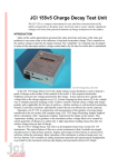
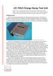
positioned over the aperture in the top surface of the JCI 176. The arrangement is shown in
Figure 1 and Figure 2.
The top plate of the JCI 176 can be swung up on its hinges at the back so samples can be
placed between the plates over the aperture area. It is important to make sure that samples lie
nice and flat and without wrinkles, etc. The top surface of the sample should be free of loose
dust, particles and fibres and without projections that could get into the test aperture of the JCI
155. The top plate of the JCI 176 can usually be lifted sufficiently to enable samples to be
positioned without removing the JCI 155 from on top.
Power for operating the JCI 176 may be provided by the two PP3 batteries in the battery
compartments on the left side of the back of the unit. This supply is switched on by the slide
switch on the right hand side of the back of the unit - the red led shows power is ON. If the
JCI 176 is operated in conjunction with a JCI 155v5 Charge Decay Test Unit, with an 8w-8w
mini DIN connection cable link between the units, then power is provided directly to the JCI
176 without need for batteries or for the JCI 176 unit to be switched on.
It is important that the earth bonding point of the JCI 176 mounting box is connected to
the earth bonding point of the JCI 155 instrument. A combination ‘Durable Dot’/4mm
bayonet socket earth bonding point is provided to enable the casing of the unit to be bonded to
the associated JCI 155. It is also desirable that the whole assembly is connected to earth to
minimise risks of interference of fieldmeter observations by pick-up of 50Hz signals.
The sample mounting plates are part of the active charge measurement circuits. It is hence
important that these plates do not contact anything grounded or anything that may have
charge induced on it. This means that when working with samples which include high
conductivity components that samples are cut which do not extend much beyond the
mounting plates or that these samples are isolated or carefully supported on insulation and left
undisturbed during the duration of testing. It is also wise when making charge decay studies
involving small quantities of charge that the overall assembly is not affected by external
alternating fields. This may be checked by looking at the ‘conduction’ signal displayed on an
oscilloscope.
The charge sensing circuits are designed to hold observed charge signals for long times to
make measurement of charge values easy using, for example, digital multimeters on the
analogue output channels. Typical charge leakage rates at both conduction and induction
inputs are around 0.1pC s-1 (10-13A). It is usual to zero the charge measurement circuits before
each measurement. However if the circuits are not zeroed then observations will be additive
within the dynamic range of the measurement circuits – to outputs around +4.5V.
For high sensitivity measurements, it is best to hold the circuits in the zeroed state until
measurements are to be made. When used in conjunction with a JCI 155v5 Charge Decay
Test Unit the charge measuring circuits are held in the zeroed state until just before
measurements are to be made and then released by the software program within the JCI
155v5. When used with other instruments, for example a JCI 155v4, the charge measuring
circuits need to be zeroed either by connecting pin 5 of one of the mini DIN connector leads
(a violet lead) to earth or manually pressing the push button provided on the back of the unit
for a second or two. This should be held in the zero state until just before the moving plate
carrying the cluster of corona discharge points is advanced. When operated in conjunction
with a JCI 191 Controlled Humidity Test Chamber the zeroing can be accomplished with a
zeroing button outside the JCI 191 chamber.
The feedback capacitors in the virtual earth charge amplifiers are 1000nF and 100nF for
the conduction and induction signal channels. These give basic charge sensitivities
respectively of 1mV per nC of conduction charge and 10mV per nC of induction charge. As
the coupling of induction charge to the induction sensing electrode is about 0.5 the effective
sensitivity for induced charge is about 5mV per nC. The relative sensitivities of ‘induction’
and ‘conduction’ observations can conveniently be checked using by making corona charge
2