1
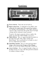
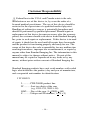
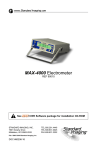
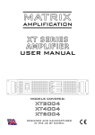
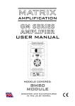
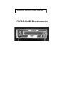
SeeDOS Product User Manual
CDX-2000B Electrometer
Table of Contents
General Precautions ................................................ 2
General Operation................................................... 3
Front Panel .............................................................. 4
Rear Panel ............................................................... 5
Features and Specifications .................................... 6
Using the CDX-2000B ........................................... 8
Maintenance.......................................................... 12
Service .................................................................. 12
Parts and Accessories List .................................... 12
Troubleshooting .................................................... 13
Customer Responsibility ...................................... 14
Warranty ............................................................... 15
©2002 Standard
Imaging
Inc.
Distributed
by SeeDOS
Ltd
For further
or a quotation please
7601
Murphyinformation
Drive
contact
Colin
Walters
at
[email protected]
Middleton, WI 53562
Tel : +44 1525 850670 Phone:(608) 831-0025
Fax: +44 1525 850685 Fax:(608) 831-2202
General Precautions
Warnings and Cautions alert users to dangerous conditions
that can occur if instructions in the manual are not obeyed.
Warnings are conditions that can cause injury to the operator, while Cautions can cause damage to the equipment.
WARNING: An electrical shock hazard of up to
300 VDC is possible whenever the bias
voltage is active. Always set the bias
to the 0% or 0 VDC level whenever a
device is connected to or disconnected
from the CDX-2000B.
CAUTION: Proper use of this device depends on careful
reading of all instructions and labels.
CAUTION: Input voltage on triax connector should
be no greater than +5V or -5V.
CAUTION: This device should never be submerged
in water or a solvent to clean, or
scrubbed with an abrasive cleaner. Do
not drop or mishandle unit. Calibration
factor changes may result.
CAUTION: Do not disassemble unit since it may
result in change of calibration factor.
Refer servicing to qualified individuals.
–2–
General Operation
1. With nothing connected to the input jack of the CDX2000B, turn the power on and wait at least 15
minutes for the electrometer to warm up.
2. Press the Start button to perform the electrometer
zero adjustment. This will take about one minute.
3. Connect the ionization chamber to the CDX-2000B
and select the desired voltage bias. Allow at least 10
minutes for the system to stabilize.
4. Verify the leakage of the ionization chamber is within
the manufacturer’s stated acceptable limits.
5. Press and hold the Mode button and repeat the zeroing process in Step 2, but with the ionization chamber
connected. This is the system zero adjustment.
6. Check the system leakage. Take a reading without
exposing the chamber to radiation. This reading
should be less than 0.1% of the final signal expected.
7. Measure the atmospheric temperature and pressure.
8. Turn on or insert the radiation source(s) and take at
least 3 measurements. Further explanation of the
Rate, Charge and Charge/Rate modes can be found on
page 10 and 11.
9. Analyze the data taking into account the average of
the readings, system leakage, temperature/pressure
corrections, calibration factors and any other
appropriate corrections to be made.
10. When all measurements are completed, set bias
voltage to 0VDC, turn off the CDX-2000B and
disconnect the ionization chamber.
–3–
Front Panel
1
5
2
3
4
1
Power button: Turns the unit off and on.
2
Input connection: A standard two lug, BNC, triax
connector for signal input. This connector features
low leakage current properties. The signal current is
carried on the central lead, the guard carries the high
voltage and the outermost ring is ground.
To protect the input connector, always replace the
chain cap when the CDX-2000B is not in use.
3
Mode button: Press to toggle through the modes in
the following order: Bias, Rate, Charge and
Rate/Charge. Press and hold for 2 seconds to select
the zero adjustment procedure.
4
Start/Reset button: Press to start and stop timed
charge collections in the Charge or Rate/Charge
mode, or to reset the display following a collection.
5
Arrow buttons: Press to toggle through voltages in
the Bias mode or to select the time period increments
for taking a charge reading.
–4–
Rear Panel
1
2
3
1
2.5mm Battery Charger Input: Connect the battery
charger to this input jack when charging the internal
battery. Note: If the CDX-2000B is being used in a
patient environment, do not plug in the charger.
Connect to mains power through an isolation transformer only.
2
RS-232 serial port: A standard 4 conductor telephone cable may be used to connect to the serial port
for remote observation or data recording. A 15’ cable
and DB-9 female adapter (for connection to the
computer) has been provided. Do not connect RS-232
serial port to the telephone line. This port is for
connection to equipment where no risk of external
voltage exists.
3
External reset switch: In the unlikely event that the
device stops responding, use a small diameter rod to
lightly press the internal button and reset the device.
–5–
Features and Specifications
Rate Mode Range ......................0.01nA - 195.00nA
Charge Mode Range ..................0..01nC - 999,999nC
Selectable time periods for charge collection
Range ......................................0 - 600 seconds
Increments ..............................15 sec
Resolution...............................1 sec
Other mode ................................“free running”
Repeatability
Short term ..............................±0.1% + one count
Long term ..............................±0.2% (max change over 2 yrs)
Signal settling time (typ)........ < 1 sec
Linearity ....................................±0.06% 1nA to 200nA, typical
Leakage ......................................< 5fA at STP
Operating Conditions
Pressure.................................680 to 770 mm Hg
Temperature..........................10 to 40 °C
Relative Humidity.................20 to 80%, non-condensing
Storage and Transport Conditons
Pressure.................................600 to 800 mm Hg
Temperature..........................-15 to 50 °C
Relative Humidity.................10 to 95%, non-condensing
–6–
Display .......................................LCD, 2 x 20 with 5/16 in. high
letters for easy viewing
Input ...........................................BNC two lug, triaxial connector
Bias Voltage ...............................Nominal ±300 volt bias
Five user settings .......................-300, -150, 0, 150, 300 (VDC)
Power .........................................UL listed wall-mounted power
supply, 110 or 220 VAC input,
9VDC@300mA output
Zeroing ......................................Automatic zero function, user
activated
Output ........................................Isolated RS-232, uni-directional
19,200 baud, 8 data bits,
no parity, 1 stop bit
Dimensions (w,h,l) .....................8.24 x 2.75 x 9 in.
(22.2 x 7 x 23 cm)
Weight ........................................3.0 lbs. (1.4 kg)
Specifications subject to change without notice.
–7–
Using the CDX-2000B
Before using the CDX-2000B to take measurements,
perform the following steps to ensure accurate readings.
The CDX-2000B features an automatic zero function and a
convenient way to check battery status and bias level.
Automatic Warm Up and Zero Adjust
1. Turn on the CDX-2000B. The display will count
down 15 minutes of recommended warm up time.
2. When the display reads “Press START to zero,” press
the Start/Reset button to perform the zero adjustment.
This process will take 60 seconds..
3. The display will read “ZEROING COMPLETE.”
The CDX-2000B will now default to the Bias mode.
Note: To perform a zero adjust measurement after making
other measurements, press and hold the Mode
button for two seconds. Repeat steps 2 - 3 above.
Bias Mode
1. The charge level of the internal battery is displayed in
percent. When the battery capacity drops below 15%,
the display will read “RECHARGE BATTERY.”
2. Use the arrow keys to select the bias level from the
following options.
-100%
-300VDC
-50%
-150VDC
0%
0VDC
+50%
150VDC
+100%
300VDC
–8–
3. Press the Mode button to select a mode of operation.
You may return to the Bias mode at any time to
change the bias voltage.
CAUTION: When connecting or disconnecting an
ionization chamber to the CDX2000B, set the Bias voltage to 0%
(0VDC).
Rate Readings
1. Use the Bias mode to set the bias voltage.
2. Use the Mode button to select the Rate Mode.
3. Irradiate the ion chamber with a radioactive source.
4. The CDX-2000B will begin to measure the current.
Wait about 3 seconds for stabilization.
5. The Rate measurement will be displayed.
NOTE: Rate measurements of 195.00 nA and greater will
produce an “OVERLOAD” message.
Charge Readings
1. Use the Bias mode to set the bias voltage.
2. Use the Mode button to select the Charge Mode.
3. Use the arrow keys to select the collection time. Time
periods from 0 - 600 seconds are available in 15
second increments.
4. Irradiate the ionization chamber.
5. Press the Start/Reset button. The CDX-2000B will
count down from the time set and display the charge
accumulated. When the countdown is complete, the
charge accumulated will remain until the unit is reset.
–9 –
6. Record the reading and press the Start/Reset button to
clear the reading and reset to the chosen collection
time.
7. Repeat steps 3 - 6 for other charge readings.
NOTE: Charge measurements of 999,999 nC and greater,
will produce an “OVERLOAD” message.
Rate/Charge Readings
1. Use the Bias mode to set the bias voltage.
2. Use the Mode button to select the Rate/Charge Mode.
The CDX-2000B will begin to measure current.
3. Use the arrow keys to select the collection time. Time
periods from 0 - 600 seconds are available in
15 second increments.
4. Irradiate the ionization chamber with a radioactive
source.
5. To take charge measurements and rate measurements
simultaneously, press the Start/Reset button. The
CDX-2000B will count down from the time set and
display the charge accumulated.
6. When the countdown is complete, the charge
accumulated will be displayed until the unit is reset.
7. Record the charge reading and press the Start/Reset
button to clear the reading and reset to the chosen
collection time.
8. Repeat steps 3 - 7 for other charge readings.
– 10 –
Charging the internal battery
1. When the battery capacity is 15% or “RECHARGE
BATTERY” appears on the display, plug the 2.5 mm
jack of the charger into the electrometer and the other
end into mains power.
2. Whenever the battery is being charged, the Battery
percent display in the Bias mode will indicate
“100%”.
3. The CDX-2000B will also operate with the charger
plugged into a wall outlet, irregardless of the battery
capacity. Re-charging the battery takes 6 - 8 hours.
The CDX-2000B may be continually charged with no
detrimental effects to the internal battery.
Automatic Shutdown
To maximize battery life, the CDX-2000B will shut
off
automatically if it is not plugged into the wall
charger and is left unattended for more than 3 hours.
– 11 –
Maintenance
As is standard practice for other electrometers, it is recommended that the CDX-2000B be calibrated every 2 years.
This calibration should be performed by an Accredited
Dosimetry Calibration Laboratory.
Exterior cleaning of the device can be done with a soft
brush and a cloth. Gently brush all surfaces to remove dirt
and dust. Remove any remaining dirt with a cloth slightly
dampened with a solution of mild detergent and water or a
liquid disinfecting agent. Do not use water or liquid on
triax output. Do not permit any liquid to seep into the
CDX-2000B in any manner during cleaning. It is not
recommended to clean the window of the LCD with anything other than a mild detergent and a very soft cloth.
Failure to use a soft cloth may result in a scratched window,
this may impair the visibility of the LCD.
Service
Qualified users may replace the Lead Acid battery only. An
illustrated Instruction Booklet is available. See the Parts
and Accessories List below. There are no other user serviceable parts in the CDX-2000B.
Parts and Accessories List
REF
80316
72011
76007
72013
73006-110
73006-220
Description
Instruction Manual
Battery Charger, 110 VAC*
Battery Charger, 220 VAC*
Telco® Adapter Kit, RJ-11 to DB-9F
Lead Acid Battery Replacement Kit,
including 110VAC wall charger
Lead Acid Battery Replacement Kit,
including 220 VAC wall charger
– 12 –
Troubleshooting
Questionable Readings
If readings are off, determine if there is any leakage from
the CDX-2000B or ionization chamber. Follow steps 1 - 7
under General Operation.
Can’t Get Out of Charge Mode or Rate/Charge Mode
Upon completion of a charge collection in the Charge or
Rate/Charge mode, Start/Reset must first be pressed to
reset the display before other buttons will function.
No Response
If the system does not respond to any of the buttons, use the
external reset switch. See page 5 for details.
Low Battery
The CDX-2000B contains 1 rechargeable sealed lead-acid
battery with a life of about 10 hours. When the battery is at
15% of capacity, “RECHARGE BATTERY” will appear on
the display. If the battery becomes low during a charge
collection, the screen will alternate between “RECHARGE
BATTERY” and the status of the collection. The collection
process will not be interrupted.
The CDX-2000B will also operate with the charger plugged
into a wall outlet. Re-charging the battery takes 6 - 8 hours.
The CDX-2000B may be continually charged when not in
use with no detrimental effects to the internal battery.
The CDX-2000B will shut off automatically if it is not
plugged into the wall charger and is left unattended for
more than 3 hours.
If you require further assistance, please contact Standard
Imaging’s Service Department at (608) 831-0025.
– 13 –
Customer Responsibility
Federal law in the U.S.A. and Canada restricts the sale,
distribution or use of this device to, by or on the order of a
licensed medical practitioner. The use of this device should be
restricted to the supervision of a qualified medical physicist.
Handling of radioactive sources is potentially hazardous and
should be performed by qualified personnel. Should repair or
replacement of this device become necessary after the warranty
period, the customer should seek advice from Standard Imaging
Inc. prior to such repair or replacement. If this device is in need
of repair, it should not be used until all repairs have been made
and the product is functioning properly and ready for use. The
owner of this device has sole responsibility for any malfunction
resulting from abuse, improper use or maintenance, or repair by
anyone other than Standard Imaging Inc. The information in this
manual is subject to change without notice. No part of this
manual may be copied or reproduced in any form, or by any
means, without prior written consent of Standard Imaging Inc.
Standard Imaging products have unit serial numbers with coded
logic which indicates the product, day and year of manufacture,
and a sequential unit number for identification:
J YY DDD X
J.............CDX-2000B product line
YY............Last two digits of the year
(e.g. 1999 = 99, 2000 = 00)
DDD.......Day of the year (1 < DDD < 365)
X.............Unique unit ID number (1 < X < 9)
– 14 –
Warranty
Standard Imaging, Inc. sells this product under the warranty herein set
forth. The warranty is extended only to the buyer purchasing the product
directly from Standard Imaging, Inc. or as a new product from an authorized dealer or distributor of Standard Imaging, Inc.
For a period of twenty-four (24) months for well chambers and twelve
(12) months for all other Standard Imaging, Inc. products from the date
of original delivery to the purchaser or a distributor, this product is warranted against functional defects in materials and workmanship, provided
it is properly operated under conditions of normal use, and that repairs
and replacements are made in accordance herewith. The foregoing warranty shall not apply if the product has been dissembled, altered or repaired other than by Standard Imaging, Inc. or if the product has been
subject to abuse, misuse, negligence or accident.
Standard Imaging’s sole and exclusive obligation and the purchaser’s sole
and exclusive remedy under the above warranties are limited to repairing
or replacing free of charge, at Standard Imaging’s option, a product: (1)
which contains a defect covered by the above warranties; (2) which are
reported to Standard Imaging, Inc. not later than seven (7) days after the
expiration date of the 12 or 24 month warranty period; (3) which are
returned to Standard Imaging promptly after discovery of the defect; and
(4) which are found to be defective upon Standard Imaging’s examination. Transportation charges are the buyer’s responsibility. This warranty
extends to every part of the product except fuses, batteries, or glass breakage. Standard Imaging, Inc. shall not be otherwise liable for any damages, including but not limited to, incidental damages, consequential damages, or special damages. Repaired or replaced products are warranted
for the balance of the original warranty period, or at least 90 days.
This warranty is in lieu of all other warranties, express or implied, whether
statutory or otherwise, including any implied warranty of fitness for a
particular purpose. In no event shall Standard Imaging, Inc. be liable for
any incidental or consequential damages resulting from the use, misuse
or abuse of the product or caused by any defect, failure or malfunction of
the product, whether a claim of such damages is based upon the warranty,
contract, negligence, or otherwise.
This warranty represents the current standard warranty of Standard
Imaging, Inc. Please refer to the labeling or instruction manual of your
Doc. No. 80316-02, 03-11-02, 15 pgs