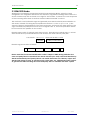
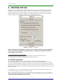
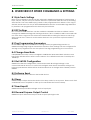
1
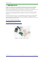
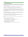
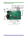
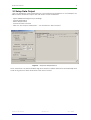
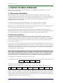
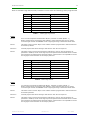
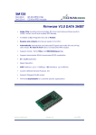
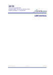
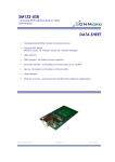
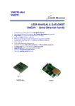
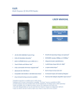
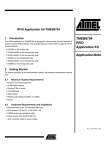
SM125 System
SM125-IC 125 KHz RFID Chip
SM125-M1 125 KHz RFID Module
SM125-EK Evaluation Kit
SMRFID 3.0 Software
USER MANUAL
SonMicro Electronics
Revision A.1
May, 2008
2
SM125 User Manual
1.
INTRODUCTION
4
1.1 125 KHz RFID Systems
5
1.2 Evaluation Board Layout View
6
1.3 SM125-EK / SM4005 Schematic
7
2. FAST STARTING GUIDE – SETUP & GO
8
2.1 Setup Auto Mode
8
2.2 Setup Data Output
9
3. THEORY OF READ OPERATION
10
3.1 Manchester Modulation
10
3.2 Byte Track Method
10
3.3 EM4102 Mode
12
4.
READING THE TAG
13
4.1 Read Command
13
4.2 Stop Read Command
14
4.3 Auto Mode
14
5.
DATA OUTPUT SETTINGS
15
5.1 UART Serial
15
5.2 Wiegand 26 Bit
15
5.3 Output0
15
6.
TAG PROGRAMMING
16
7.
CALIBRATION
18
8.
OVERVIEW OF OTHER COMMANDS & SETTINGS
20
8.1 Byte Track Settings
20
8.2 I2C Settings
20
8.3 Tag Programming Parameters
20
8.4 Change Baud Rate
20
8.5 Get SM125 Configuration
20
SonMicro Electronics
Revision A.1
May, 2008
3
SM125 User Manual
8.5 Software Reset
20
8.6 Sleep
20
8.7 Read Input0
20
8.8 General Purpose Output Control
20
9. SALES AND SERVICE INFORMATION
SonMicro Electronics
Revision A.1
21
May, 2008
4
SM125 User Manual
1. INTRODUCTION
SonMicro’s primary products for 125KHz RFID is the SM125-IC chip and the SM125-M1
modules. To evaluate, test, demonstrate or develop any application with the SM125
devices, the best, painless and the quickest way is to obtain a low cost SM125-EK
Evaluation Kit. SM125-EK together with the SMRFID V3.x Software is just everything the users
need. SM125-EK kit includes evaluation board, module, tags and antennas.
SM125-EK is a professional evaluation kit for SM125-M1 modules. The kit includes power
supply for the module, RS232 connection, I2C pins, LCD connector, and the antenna
connector.
SM125-EK communicates with PC over RS232 (DB9 female jack) serial port (USB-to-Serial
converters works fine) at different baud rates from 9600bps to 115200bps (19200bps
default). SM125-M1 module can also communicate with external peripheral over I2C bus
with the provided I2C pins on the kit.
For latest Documentation & Software:
http://www.sonmicro.com/125/d125.php
For World Wide Online Store:
http://www.sonmicro.com/shop/shop3.php
Figure 1 – SM125-EK-D Evaluation Kit Photo
SonMicro Electronics
Revision A.1
May, 2008
5
SM125 User Manual
1.1 125 KHz RFID Systems
SonMicro’s solution for 125 KHz RFID is unique in the world. The SM125-IC chip includes both
RFID analog system and microcontroller in the same package. Competitors offer only the
analog chip and left the complicated decode operations to the user to be done by the
external microcontroller.
The most used applications for the 125 KHz RFID systems is in general the person
identification, specifically access control, time & attendance systems, and the part
identification i.e. the immobilizer systems used in automotive applications.
The read range in a 125 KHz RFID system is generally between 5 – 15 centimeters, typically
8cms (~3.5 inches). The read range varies according to the antenna size, tag size, shape
and the material. For example the clamshell cards, a bit thicker than ISO cards, have
better performance than ISO cards, where TK type (i.e. TK5551, TK5530) 2-3 mm sized tags
have low performance.
The most popular tag used in 125 KHZ RFID systems, generally called EM, is EM4102 readonly tags. These tags have less cost and are ideal for person identification. T5557, or Q5
(T5555) re-writeable tags have also pie in tag market.
The most popular modulation is the Manchester RF/64 type modulation. The other
modulation types such as FSK, PSK have very specific application and are not widely
used. FSK and PSK is not supported by SM125 devices.
SonMicro developed SM125 devices according to the most used standards explained
above.
125 KHz RFID advantages over 13.56MHZ RFID
-
Reader components such as IC, module is significantly cheaper
Better performance behind the metallic objects.
Cheaper tags can be found such as EM4102
125 KHz RFID disadvantages over 13.56MHZ RFID
- Less secure than 13.56 MHz
- Writing to tags continuously for data storage is not practical and slow.
SonMicro Electronics
Revision A.1
May, 2008
6
SM125 User Manual
1.2 Evaluation Board Layout View
Figure 2 – SM125-EK-D Evaluation Board Description
SonMicro Electronics
Revision A.1
May, 2008
7
SM125 User Manual
1.3 SM125-EK / SM4005 Schematic
SonMicro Electronics
Revision A.1
May, 2008
8
SM125 User Manual
2. FAST STARTING GUIDE – SETUP & GO
This section is prepared for those who want to make a very fast starting without
investigating SM125 usage details. The following example is given to read EM4102 tags,
and output the EM4102 data as ASCII characters with Carriage Return (CR) and LF (Line
Feed) characters. The example is chosen for the most used operation in the field. Once
the following “Auto Mode” and “Data Output” settings is done then the SM125 will act
with the same settings even after Power-On-Reset because the necessary settings is
stored in flash memory of SM125 and they are loaded each time after reset.
2.1 Setup Auto Mode
- Connect the SM125-EK to the PC and open SMRFID v3.x software.
- Select the appropriate port and 19200bps
- Select the EM4102 parity decoded option in the main window
- Uncheck Send Password
- Select 2 for Number of Blocks to be Read
- Select Enable and click on “Set Auto Mode”. You should see “RX> Success” in the
Comport Activity and Information Box.
Figure 3 – Setup Auto Mode
SonMicro Electronics
Revision A.1
May, 2008
9
SM125 User Manual
2.2 Setup Data Output
User can determine output behavior for a successful read operation. In our example, we
will use ASCII character output with CR and LF footer characters.
-
Open SMRFID>Settings>Output Settings
Check UART/Serial
Select Simple ASCII
Check CR and LF footers
Click on “Set Output Parameters” . You should see “ RX> Success”
Figure 4 – Setup Data Output Behavior
Now, whenever you place EM4102 tag near antenna, SM125 will read it automatically and
send as tag data as ASCII characters with CR+LF footers.
SonMicro Electronics
Revision A.1
May, 2008
10
SM125 User Manual
3. THEORY OF READ OPERATION
There are two options for the read operation according to the modulation and the
method used in the tag.
3.1 Manchester Modulation
SM125 supports Manchester RF/64 and Manchester RF/32 modulations in the V3.0x
firmware. The Manchester RF/64 is the most used modulation type in 125 KHz systems and
is recommended to be used for new designs. Manchester RF/32 is used in some tags (e.g.
TK5552) but the read performance is lower than the Manchester RF/64 and not
recommended for new designs.
For Manchester RF/64, signal representing 1 or 0 is in 512us width for 125 KHz.
For Manchester RF/32, signal representing 1 or 0 is in 256us width for 125 KHz.
EM4102 tags use Manchester RF/64 modulation and EM method and the configuration of
these read-only tags is fixed and can’t be altered.
T5557/T5555/Q5 re-writeable tags that are delivered by SonMicro are configured for
Manchester RF/64 modulation and “Byte Track” method. Note that T55xx tags purchased
from other resources can be configured for different modulation and methods.
3.2 Byte Track Method
Whether the modulation is Manchester RF/32 or Manchester RF/64, when the tag is
energized in the magnetic field across the antenna, tag will be sending data consist of 1s
and 0s continuously with no break or no sign for the header. To detect the start sequence
of the incoming data there are two methods. One is the “byte track” method and the
other is “EM” method.
If “Byte Track” is used, SM125 device tracks 4 byte; 0x52 0x58 0x8B 0x45 as default. These
settings can be changed. SM125 device can trace for 1 byte, 2 byte, 3 byte or 4 byte. The
most reliable and recommended option is to trace for 4 byte. Note that the traced bytes
should not repeat elsewhere in the incoming data stream, otherwise the header/block1
synchronization can be wrong.
Please note that, if the tag does not include bytes to be traced, then that tag can not be
read. T555x re-writeable tags needs to use Byte Track method and so the first block needs
to be written/programmed with the bytes to be traced. There is a way to program T555x
transponders acts as an EM4102 tag, but this is explained in another application note.
Incoming and continuous data stream from the tag:
11110000011100100…0101 0010 0101 1000 1000 1011 0100 0101…000111010010011111001
0x52
0x58
0x8B
0x45
T555x Tags send data as follows:
(Example is given for 3 blocks is transmitted by the tag. Each block has 4 byte data)
…
Block1
Block2
Block3
Block1
Block2
Block3
Block1
…
Block1 should be programmed with 0x52 0x58 0x8B 0x45 so that when SM125 catch these
bytes, it will be synchronized and assume 0x52 0x58 0x8B 0x45 as the first block. If Block1 is
programmed with another traceable bytes, then these new bytes should be configured in
SMRFID>Settings>Byte Track Settings window.
SonMicro Electronics
Revision A.1
May, 2008
11
SM125 User Manual
T555x re-writable tags delivered by SonMicro comes with the following data programmed
Block No
Block Description
Programmed Content
0
Configuration Block
60 01 F0 0E
1
Data Block / Trace-able Block
52 58 8B 45
2
Data Block
02 02 02 02
3
Data Block
03 03 03 03
4
Data Block
04 04 04 04
5
Data Block
05 05 05 05
6
Data Block
06 06 06 06
7
Data Block / Password Block
00 00 00 00
Table 1 – T5555 (Q5) Tag Content
Notes:
Block 0
60 01 F0 0E corresponds to Manchester RF/64 , transmit of 7 block (Block1..7)
Block0 should not be programmed with arbitrary values otherwise the tag may not be
accessed again. Please use SMRFID>Tools>Tag Programming to determine block0 data.
Block 1
This block can be used for “Byte Track” method. What is programmed in this block should
be traced by SM125.
Block 2-6
General purpose data bock. Writing to this block is safe. No care required.
Block 7
This block can be used as general purpose data block or can be used as password. If
password is enabled, access to the tag requires the password that matches block7 content.
Once password is enabled and if the block7 data is unknown then it is impossible to access
the tag again unless with the correct 4 byte password.
Block No
Block Description
Programmed Content
0
Configuration Block
0014 80 E0
1
Data Block / Trace-able Block
52 58 8B 45
2
Data Block
02 02 02 02
3
Data Block
03 03 03 03
4
Data Block
04 04 04 04
5
Data Block
05 05 05 05
6
Data Block
06 06 06 06
7
Data Block / Password Block
00 00 00 00
Table 2 – T5557 Tag Content
Notes:
Block 0
00 14 80 E0 corresponds to Manchester RF/64 , transmit of 7 block (Block1..7)
Block0 should not be programmed with arbitrary values otherwise the tag may not be
accessed again. Please use SMRFID>Tools>Tag Programming to determine block0 data.
Block 1
This block can be used for “Byte Track” method. What is programmed in this block should
be traced by SM125.
Block 2-6
General purpose data bock. Writing to this block is safe. No care required.
Block 7
This block can be used as general purpose data block or can be used as password. If
password is enabled, access to the tag requires the password that matches block7 content.
Once password is enabled and if the block7 data is unknown then it is impossible to access
the tag again unless with the correct 4 byte password.
SonMicro Electronics
Revision A.1
May, 2008
12
SM125 User Manual
3.3 EM4102 Mode
Whether the modulation is Manchester RF/32 or Manchester RF/64, when the tag is
energized in the magnetic field across the antenna, tag will be sending data consist of 1s
and 0s continuously with no break or no sign for the header. To detect the start sequence
of the incoming data there is another method called “EM4102” method.
This method is used in EM4102 tags and generally uses Manchester RF/64 modulation. In
this mode, instead of tracing bytes explained in section 2.1, nine 1s (1111 1111 1) are
traced to detect the beginning of the data sequence. Moreover the data written in the
tag is created with parity bits so that even a tag has nine 1s, the read operation will not
be successful if the parities do not match.
EM4102 tags consist of 2 blocks each have 4 byte. These 8 bytes include nine 1s, actual
data that is the 5 byte identification code and the row and column parity bits.
1111100100…1111 1111 1…000111010010011111001
Header
Parity coded data
EM4102 tag sends data as follows:
…
Block1
Block2
Block1
Block2
…
Please note that, the actual identification code is 5 Bytes in EM4102 tag. With the nine
ones and parity bits the raw data is two blocks each 4 byte. Parity check will be done by
SM125 automatically and if parity bits do not match then there won’t be any output and
SM125 keep trying to read. To get the actual 5 byte data, use “EM4102 decoded” option.
To get the raw data including nine ones and parity bits use “EM4102 raw data” option.
SonMicro Electronics
Revision A.1
May, 2008
13
SM125 User Manual
4. READING THE TAG
Reading can be initiated by UART/I2C command or, can be automated if Auto Read
mode is used. For most systems, auto mode is recommended so that system may not
require any external microcontroller. Once auto mode is setup, module will read and
output tag data whenever is available. The tag data will be outputted only one time
while the tag is in the magnetic field across the reader antenna.
Figure 5 – SMRFID – Read Panel
Please note that if the SREAD LED on the kit is ON, and then it means the read operation is
active and SM125 is seeking for tag. While there is a valid tag in the field that matches
read settings, TAGF will blink.
For the tags delivered by SonMicro:
For EM4102 tags, use EM4100/02 parity decoded or the EM4102/raw option
For T555x tags, use the Byte track Manchester RF/64 option.
4.1 Read Command
This command initiates a new read operation with the selected parameters.
User can select Read Type, number of blocks to be read, and determine if the read is
done by first accessing the tag with a password. If the tag is password protected, please
remember that password is the block7 data of the tag. If password option is selected, the
SREAD LED will blink around each second indicating the 4 byte password is sent to the tag
in each period.
For beginners, it is not recommended to protect the tag with a password. Tag may not
be accessible again in case of in proper usage.
Please note that; If Read is going to be done by Read Command in the system, then it is
recommended to disable Auto Read mode.
SonMicro Electronics
Revision A.1
May, 2008
14
SM125 User Manual
4.2 Stop Read Command
This command will stop the read operation. SREAD LED should be OFF after this command
is sent. A new read can start only:
-
if Read command is sent,
After Power-On-Reset provided that auto mode was enabled.
Enabling auto-mode
4.3 Auto Mode
This command enables or disables and sets auto mode parameters. Once the
parameters set as in Read Command section, the parameters are stored in the flash
memory permanently and the same configuration will be valid until a new setup.
User can select the Read Type, number of blocks to be read, and check password box if
password is required to access tags. Once parameters are defined, select “Enable” and
click on the Set Auto Mode. Now, even after Power-On-Reset, SM125 read operations will
be active according to determined parameters and SM125 outputs tag data whenever is
available. To disable the Auto Mode, select “Disable” and click on the “Set Auto Mode”
button.
SonMicro Electronics
Revision A.1
May, 2008
15
SM125 User Manual
5. DATA OUTPUT SETTINGS
The output behavior of SM125 after a valid tag is read, can be adjusted in
SMRFID>Settings>Output Settings. If the existing selections do not meet your requirements,
please feel free to contact us for the output selection you require.
Figure 6 – SMRFID – Output Settings
5.1 UART Serial
In this section, UART/RS232 output can be enabled or disabled and UART/RS232 output
behavior can be selected.
If Simple ASCII mode is selected, then the bytes in the tag are converted to ASCII
characters. For example one byte 0x52 is converted to ‘5’ and ‘2’ two bytes. The Carriage
Return (CR) and Line Feed (LF) characters can be added to the end of tag data.
5.2 Wiegand 26 Bit
In this section, Wiegand output can be enabled or disabled and the required parameters
can be selected.
Wiegand 26 bit is consisting of 3 bytes with 2 bits parity. The actual 3 byte, Facility and
Identification code can be set easily with flexible options.
5.3 Output0
Output0 can be enabled to be ON for a determined period just after a successful tag
read. It is useful to trigger a relay or buzzer just after tag data is read. Please note that
external transistor circuit may be required to drive the target component.
SonMicro Electronics
Revision A.1
May, 2008
16
SM125 User Manual
6. TAG PROGRAMMING
To program a re-writeable tag (T555x) open SMRFID>Tools>Program Tag window. Please
note that EM4102 tags are read-only and can’t be programmable.
Block0 data will automatically be reconstructed according to the parameters chosen.
Figure 7 – SMRFID – Writing to Tag
Please note that when programming Block0 a special care should be taken. Each tag
type has different settings for Block0. Programming Block0 with inappropriate data will
cause tag to be useless. Thus when programming Block0, make sure the selected tag in
the software and tag to be programmed is the same type. For example, T5551 block0
should not be programmed to Q5 (T5555) block0.
Please note that when programming Block1 a special care should be taken. This block is
allocated for “Byte Track” mode. This is the only way to read these tags. A known pattern
should be captured and then tag can be read. This block is programmed with 0x52 0x58
0x8B 0x45 as default and SM125 tracks for these bytes. If the block 1 content is going to be
changed then SM125 Byte Track settings needs to be changed as well for the new traceable bytes
Please note that when programming Block7 a special care should be taken if the
password is going to be enabled. If password is enabled in block0 configuration, and after
block0 is programmed, access to the tag needs to be done with a 4 byte password. The
password is 4 byte and the block7 data. Thus user need to know what is written to block7.
SonMicro Electronics
Revision A.1
May, 2008
17
SM125 User Manual
Before programming a tag, if the read operation is active, stop the operation by Stop
Read command. The SREAD LED should be OFF. Otherwise the tag programming can be
unsuccessful or wrong data can be written to tag which may cause tag to be useless.
When programming a tag, the best practice is holding the tag over the antenna about 34 cm (1 – 1.5 inches) distance. While tag is being held over the antenna, click on PRG BLKx
buttons to program desired block. Please note that success response does not mean, the
tag is programmed successfully but indicates that the tag programming functions called
internally and the write sequence has been finished. To confirm the tag is programmed
the only way is to read the tag and check the values manually.
SonMicro Electronics
Revision A.1
May, 2008
18
SM125 User Manual
7. CALIBRATION
SM125 modules are calibrated in the factory. However for the tag type and antenna
used, calibration may need to be done again for better performance.
RADF = Antenna Drive Frequency 12MHz / (RADF+1)
93 will yield = 127.6 KHz
94 will yield = 126.3 KHz
95 will yield = 125.0 KHz
96 will yield = 123.7 KHz
97 will yield = 122.4 KHz
98 will yield = 121.2 KHz
Please note that, for best read range RADF should not be necessarily 125 kHz and can
vary around 125 KHz.
Other parameters are quite technical details which are internal parameters and also
there is no linear or mathematical relation that can explain read range according to their
values.
For your reference, the default parameters used in SM125-IC and module are:
RADF:
A1:
A2:
A3:
G1:
G1:
97
2
3
3
24
24
RADF:
A1:
A2:
A3:
G1:
G1:
96
3
3
3
24
24
The actual calibration parameters will be programmed to SM125 is found at the right
hand side of the window where “SET” buttons and “Set All” button exist. The parameters
at the left hand side are the selections that SMRFID software will try each condition.
Figure 8 – SMRFID – Writing to Tag
To make the calibration automated, place a tag over the antenna with the desired
distance (Using books, or some non-metallic material can be used to put on the
antenna). Starting with 7-8 cm is a good practice.
Try to keep Start and End parameters close to each other, so there won’t be many trying.
Otherwise the calibration process may take a long time. Click on the Auto Calibrate
button. SM125 will be set with the defined parameters at left hand side one by one, and if
there is a tag read, that parameter will be written into the text box above the Auto
SonMicro Electronics
Revision A.1
May, 2008
19
SM125 User Manual
Calibrate button. After all selections are tried then auto calibration process will stop. User
now can increase the distance between the tag and antenna and click on the “ReCalibrate” button. This button will try the selections in the text box above the Auto
Calibrate button. Re-Calibrate progress is faster because there will be less amount of
possibilities. While Re-Calibrate is under progress if a tag is read successfully then the
parameters will be written into the text box above the Re-Calibrate button. Those are the
best of best selections and user can now try manually all parameters in Re-Calibrate list by
increasing the distance between the tag and the antenna and select one of the lines in
Re-Calibrate list and click on Set All button.
SonMicro Electronics
Revision A.1
May, 2008
20
SM125 User Manual
8. OVERVIEW OF OTHER COMMANDS & SETTINGS
8.1 Byte Track Settings
Bytes to be tracked by SM125 can be adjusted in SMRFID>Settings>Byte Track Settings. 1
byte, 2 bytes, 3 bytes or 4 bytes can be traced to synchronize with the start of incoming
data stream. The trace-able byte(s) needs to be programmed into block1 of the tag. In
default, SM125 trace for 4 byte: 0x52 0x58 0x8B 0x45 and the re-writeable tags delivered
by SonMicro are programmed with these 4 bytes in block1.
8.2 I2C Settings
I2C communication interface can be enabled or disabled and slave address can be
changed in SMRFID>Settings>I2C Settings window. If I2C is enabled, UART commands will
not work after a tag read. This is because SM125 will be waiting for Master to read tag
data over I2C bus. If there is no I2C Master device in the system this option should be
disabled.
8.3 Tag Programming Parameters
Re-writeable tags can have different settings for best programming practice. In
SMRFID>Settings>Tag Program Parameters window, these settings can be configured for
the tag to be programmed. Use this option if the tag programming is not successful.
8.4 Change Baud Rate
UART/RS232 baud rate can be changed in SMRFID>Set New Baud Rate window. New
baud rate will take effect after Power-On-Reset. The default baud rate for serial port is
19200bps.
8.5 Get SM125 Configuration
SMRFID>Get SM125 Configuration command reveals all settings belongs to the
connected SM125 device. It is useful to investigate and check the SM125 settings. The
retrieved parameters will be written in Information box at the right side of Read panel in
SMRFID.
8.5 Software Reset
SMRFID>Software Reset will reset the SM125 device.
8.6 Sleep
SMRFID>Sleep will put the SM125 device into sleep mode to save power. Please note that
a hardware reset is required to wake up the sM125 device from the sleep.
8.7 Read Input0
SMRFID>Read Input0 will read logic state of Input0 pin.
8.8 General Purpose Output Control
SMRFID>Output will control Output1 and Output0 pins logic state
SonMicro Electronics
Revision A.1
May, 2008
21
SM125 User Manual
9. SALES AND SERVICE INFORMATION
To obtain information about SonMicro Electronics products and technical support,
reference the following information.
SonMicro ELECTRONICS LTD.
Cankaya M. Soguksu C.
Aslihan Ishani 2/15
Mersin, 33070
TURKIYE
Phone:
Facsimile:
Email:
Web Site:
+90 324 237 21 28
+90 324 237 21 86
[email protected]
http://www.sonmicro.com
Sales
Support
Documents & Software
SonMicro Electronics
http://www.sonmicro.com/sales.php
http://www.sonmicro.com/contact.php
http://www.sonmicro.com/125n/d125.php
Revision A.1
May, 2008