Download RFID Application Kit TMEB8704

Transcript
RFID Application Kit TMEB8704
03.01
1
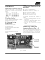
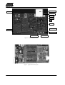
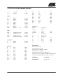
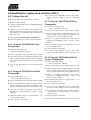
Table of Contents
1 Introduction . . . . . . . . . . . . . . . . . . . . . . . . . . . . . . . . . . . . . . . . . . . . . . . . . . . . . . . . . . . . . . . . . . . . . . . . . .
2 Getting Started . . . . . . . . . . . . . . . . . . . . . . . . . . . . . . . . . . . . . . . . . . . . . . . . . . . . . . . . . . . . . . . . . . . . . . .
2.1 Minimum System Requirements . . . . . . . . . . . . . . . . . . . . . . . . . . . . . . . . . . . . . . . . . . . . . . . . . . .
2.2 Hardware Requirements and Installation . . . . . . . . . . . . . . . . . . . . . . . . . . . . . . . . . . . . . . . . . . . . .
2.3 Hardware Settings and Connector Positions (Fig. 1, 2) . . . . . . . . . . . . . . . . . . . . . . . . . . . . . . . . . .
2.4 Software Installation . . . . . . . . . . . . . . . . . . . . . . . . . . . . . . . . . . . . . . . . . . . . . . . . . . . . . . . . . . . .
3 Description of the Application Board System . . . . . . . . . . . . . . . . . . . . . . . . . . . . . . . . . . . . . . . . . . . . . .
3.1 System Overview . . . . . . . . . . . . . . . . . . . . . . . . . . . . . . . . . . . . . . . . . . . . . . . . . . . . . . . . . . . . . . .
3.2 Power Supply . . . . . . . . . . . . . . . . . . . . . . . . . . . . . . . . . . . . . . . . . . . . . . . . . . . . . . . . . . . . . . . . . .
3.3 Antenna Interface . . . . . . . . . . . . . . . . . . . . . . . . . . . . . . . . . . . . . . . . . . . . . . . . . . . . . . . . . . . . . . .
3.3.1 Frequency Tuning Mode Selection . . . . . . . . . . . . . . . . . . . . . . . . . . . . . . . . . . . . . . . . .
3.3.2 RF Field Control . . . . . . . . . . . . . . . . . . . . . . . . . . . . . . . . . . . . . . . . . . . . . . . . . . . . . . .
3.3.3 Circuit Diagram of the Antenna Interface . . . . . . . . . . . . . . . . . . . . . . . . . . . . . . . . . . . .
3.3.4 Part List of the Antenna Interface . . . . . . . . . . . . . . . . . . . . . . . . . . . . . . . . . . . . . . . . . .
4 Identification Application Software IDS 5 . . . . . . . . . . . . . . . . . . . . . . . . . . . . . . . . . . . . . . . . . . . . . . . . .
4.1 Getting Started . . . . . . . . . . . . . . . . . . . . . . . . . . . . . . . . . . . . . . . . . . . . . . . . . . . . . . . . . . . . . . . . .
4.1.1 Using the TK5530 Read-Only Transponder . . . . . . . . . . . . . . . . . . . . . . . . . . . . . . . . . .
4.1.2 Using the TK5551 Read/Write Transponder . . . . . . . . . . . . . . . . . . . . . . . . . . . . . . . . . .
4.1.3 Using the TK5552 Read/Write Transponder . . . . . . . . . . . . . . . . . . . . . . . . . . . . . . . . . .
4.1.4 Using the TK5561 Read/Write/Crypto Transponder . . . . . . . . . . . . . . . . . . . . . . . . . . . .
4.1.5 Using the U9280M Read/Write/Crypto . . . . . . . . . . . . . . . . . . . . . . . . . . . . . . . . . . . . . .
4.1.6 Exit the Program . . . . . . . . . . . . . . . . . . . . . . . . . . . . . . . . . . . . . . . . . . . . . . . . . . . . . . .
5 Description of the RFID Application Kit Software IDS 5 . . . . . . . . . . . . . . . . . . . . . . . . . . . . . . . . . . . .
5.1 Software Structure . . . . . . . . . . . . . . . . . . . . . . . . . . . . . . . . . . . . . . . . . . . . . . . . . . . . . . . . . . . . . .
5.2 Start Window . . . . . . . . . . . . . . . . . . . . . . . . . . . . . . . . . . . . . . . . . . . . . . . . . . . . . . . . . . . . . . . . . .
5.2.1 Setup . . . . . . . . . . . . . . . . . . . . . . . . . . . . . . . . . . . . . . . . . . . . . . . . . . . . . . . . . . . . . . . .
5.2.2 Option . . . . . . . . . . . . . . . . . . . . . . . . . . . . . . . . . . . . . . . . . . . . . . . . . . . . . . . . . . . . . . .
5.2.3 Application . . . . . . . . . . . . . . . . . . . . . . . . . . . . . . . . . . . . . . . . . . . . . . . . . . . . . . . . . . . .
5.2.4 Exit . . . . . . . . . . . . . . . . . . . . . . . . . . . . . . . . . . . . . . . . . . . . . . . . . . . . . . . . . . . . . . . . . .
5.2.5 Info . . . . . . . . . . . . . . . . . . . . . . . . . . . . . . . . . . . . . . . . . . . . . . . . . . . . . . . . . . . . . . . . . .
5.3 TK5530 Read Only Transponder . . . . . . . . . . . . . . . . . . . . . . . . . . . . . . . . . . . . . . . . . . . . . . . . . . .
5.4 TK5551 Read/Write Transponder . . . . . . . . . . . . . . . . . . . . . . . . . . . . . . . . . . . . . . . . . . . . . . . . . .
5.4.1 Answer On Request . . . . . . . . . . . . . . . . . . . . . . . . . . . . . . . . . . . . . . . . . . . . . . . . . . . . .
5.5 TK5552 Read/Write Transponder . . . . . . . . . . . . . . . . . . . . . . . . . . . . . . . . . . . . . . . . . . . . . . . . . .
5.6 TK5561 Read/Write/Crypto Transponder . . . . . . . . . . . . . . . . . . . . . . . . . . . . . . . . . . . . . . . . . . . .
5.6.1 Authentication . . . . . . . . . . . . . . . . . . . . . . . . . . . . . . . . . . . . . . . . . . . . . . . . . . . . . . . . .
5.7 U9280M Microcontroller with Transponder Interface . . . . . . . . . . . . . . . . . . . . . . . . . . . . . . . . . .
5.7.1 Authentication . . . . . . . . . . . . . . . . . . . . . . . . . . . . . . . . . . . . . . . . . . . . . . . . . . . . . . . . .
2
3
3
3
3
3
5
5
5
5
5
5
5
6
7
8
8
8
8
8
8
9
9
9
9
10
10
10
11
11
11
11
12
14
15
17
19
20
22
03.01
1 Introduction
The RFID application kit (Order number: TMEB8704) is
designed to present the key features of various RFID
products from Atmel Wireless & Microcontrollers. The
included software version IDS 5 supports the following
products:
– U2270B
– TK5530 / e5530
– TK5551 / e5551
– TK5552
– TK5561 / e5561
– U9280M
on the reader side
on the transponder
on the transponder
on the transponder
on the transponder
on the transponder
2.2 Hardware Requirements and
Installation
D µC-board 1.0 with application kit 5
D R/W antenna 100 mm∅ / L = 700 µH / Q = 36
D Serial communication cabel RS232
D Power source 12 V AC/DC / 200 mA
side
side
side
side
side
D Jack connector cable for power supply
The following interconnection and conditions are
required:
2 Getting Started
For proper operation of the demonstration system, the
following requirements have to be met:
2.1 Minimum System
Requirements
– The antenna must be plugged into the socket of the
interface board.
– Communication cabling between RS232 connector
and com1 or com2 interface of the PC
– Supply line from the power source to the jack
connector
D Pentium  processor based PC
– Set the power switch to position ON
D 16 MB RAM memory
2.3 Hardware Settings and
Connector Positions (Fig. 1, 2)
D Windows 95 operation software or higher
D CD-ROM drive
D VGA monitor
In case of the RFID application, the main board with the
microcontroller is operated in a fixed configuration, no
settings are necessary.The jumper J3 on the antenna interface has to be checked according to the default setting.
D Serial interface RS232 com1 or com2
D Mouse
RS 232 Connector
Jack Connector
Power Supply
Power Switch
Reset Button
Figure 1. Main board
03.01
3
Antenna Socket
Connector J1/1
Connector J2/1
Jumper J3
CANT1
R14
CANT1
Connector J2/18
Connector J1/18
Tune 2 Indication
RF–Field Indication
Tune 1 Indication
Figure 2. Antenna interface board
Figure 3. Application board topview
4
03.01
2.4 Software Installation
The RFID application kit package includes a CD-ROM
with the installation program and the description of the
RFID application kit on the cover.
Insert the CD-ROM into the CD-ROM drive and start the
setup.exe file by means of the Windows Explorer. Then
the application program (incl. all libraries needed) will be
installed automatically step by step.
Remark:
Rights for writing into the system have to be given.
3 Description of the
Application Board System
3.1 System Overview
The RFID application board consists of a standard main
board µC-board 1.0 equipped with the Atmel microcontroller AT90S8515 combined with a piggybacked board
serving as the antenna interface.
The microcontroller AT90S8515 carries out the following
functions:
– Handling of the bidirectional data communication
between RS232 and host PC
– Execution of the read and write commands to be sent
to the antenna interface
– Decoding of the specific read data delivered by the
antenna interface
Therefore, a source program in C-language has been written. The compiled hex code is downloaded in the 8 k flash
memory of the micro. The actual program version is
indicated on the label placed on the main board.
3.2 Power Supply
indicates the actual supply voltage. For the adaption of
a specific antenna coil to the resonant frequency and the
Q-factor, the components CANT1 / CANT2 and R14
(figure 2) can be changed. The matching of the interface
depends on the added coil. The parameters and the
corresponding components for the adjustment are
described below:
Resonant frequency:
fres = 125 kHz by CANT1 / CANT2 @ Jumper 3 to
positon “Disable”
Q-factor:
Q = 20 by R14
3.3.1 Frequency Tuning Mode
Selection
The application system has a built-in tuning feature to
match the resonant frequency of the LC antenna circuit
automa-tically to the frequency of a specific transponder.
The board is equipped with two stages of high-voltage
tran-sistor switches to tune the resonator by switched capacitors. This increases the reliability and operating
distance.
The frequency tuning can be selected by the jumper J3
(figure 2):
Tuning Mode
Disabled
Enabled
Position Jumper J3
1–2
2–3
In disabled mode, the RFID application kit operates with
the fixed frequency, adjusted nominally to 125 kHz. The
tuning mode has to be enabled in order to control the tuning by the RFID application program. The binary
combination of two tuning stages enables to select one out
of four frequency states. The frequency range is extended
typically from 122 kHz to 128 kHz in steps of 2 kHz (specified in the menu of the program by “low”, “semi-low”,
“semi-high” and “high”).
For proper operation of the application board, an external
power supply in the range of DC 10 V to 15 V/ 200 mA
has to be connected to jack. A bridge rectifier placed at
the connector input is used for polarity independence.
The currently selected frequency stage is indicated in
binary mode on the application board by the red LEDs
“Tune 1” and “Tune 2” (figure 2).
3.3 Antenna Interface
3.3.2 RF Field Control
The antenna interface (figure 2) is supplied via the jack
connector located on the main board. The LED “Power”
The status of the RF field controlled by the microcontroller is indicated by the yellow LED “RF on”.
03.01
5
Á
ÁÁ ÁÁÁÁ
ÁÁÁÁ
RF
VBATT
Á
Á
Á
VEXT
Á
STANDBY
COIL2
OUTPUT
Á
INPUT
ÁÁ Á
ÁÁÁ Á
Á
Á
Á
VS
GND
DGND
COIL1
Á
OE
ÁÁ
CFE
Á
Á
Á
Á
HIPASS
3.3.3 Circuit Diagram of the Antenna Interface
6
MS
DVS
03.01
3.3.4 Part List of the Antenna Interface
U1
U2
=
=
U 2270 B
LM7808
SO16
TO220
Diodes:
D1
=
D2
=
D3
=
D4
=
D5
=
D6
=
D7
=
DZ1 =
BAS21
BAS21
BAS21
BAS21
BAS21
BAS21
BAS21
BZX84C
SOT23
SOT23
SOT23
SOT23
SOT23
SOT23
SOT23
SOT23
5.6V
LED:
LD1
LD2
LD3
LD4
=
=
=
=
TLMC3100 (green)
TLMT3100 (red)
TLMT3100 (red)
TLMA3100 (yellow)
PLCC2
PLCC2
PLCC2
PLCC2
Transistors:
T1
T2
=
=
BF820
BF820
SOT23
SOT23
3.6 kΩ
360 Ω
10 kΩ
1 kΩ
68 kΩ
43 kΩ
4.7 kΩ
470 kΩ
0805
0805
0805
0805
0805
0805
0805
0805
R12
R13
75 kΩ
100 kΩ
0805
0805
03.01
=
=
=
=
=
=
=
=
=
24 Ω
1 kΩ
3.6 kΩ
1.5 kΩ
100 Ω
1 kΩ
3.6 kΩ
1.5 kΩ
100 Ω
0805
0805
0805
0805
0805
0805
0805
0805
0805
Capacitors:
CANT1
CANT2
CTUNE1
CTUNE2
C3
C4
C5
C6
C7
C8
C9
=
=
=
=
=
=
=
=
=
=
=
2.2 nF (5%)
150 pF
100 pF
180 pF
10 µF / 16 V
22 µF / 16 V
22 µF / 16 V
220 nF
22 nF
2.2 nF
4.7 nF
0805
0805
0805
0805
0805
0805
Miscellaneous:
Resistors:
R1
=
R2
=
R3
=
R7
=
R8
=
R9
=
R10 =
R11 =
=
=
R14
R15
R16
R17
R18
R19
R20
R21
R22
SUB–D 9 pole socket
3-pole connector for Coil
gold-pin block for jumper (1x3pole)
2 gold-pin block 1x18pole
used for pin connector to the main board
The antenna coil included in the IDIC Application Kit
measures following parameters related to 125 kHz:
Inductance
Coil diameter
Winding number
Wire diameter
L = 700 µH
d = 100 mm
n = 60
dw = 0.25 mm
7
4 Identification Application Software IDS 5
4.1 Getting Started
D Read this RFID application kit user’s manual
D Install the IDS 5 software
D Connect a RS232 serial cable to the RFID application
kit and to the PC
D Connect a 12 V (AC or DC) power supply to the
RFID application kit (using the jack connector). The
status “Power on” is indicated by a green LED near the
microcontroller.
D Start the program RFID Application Software
D To read out the transponder, click on the “Read”
button in the index “Read” to show the transponder
code
4.1.3 Using the TK5552 Read/Write
Transponder
D Select the transponder type
–> Setup...Transponder...TK5552
D Place a transponder close to the base-station antenna
D Enter the transponder’s configuration details such as
bitrate, coding, ID-code length and signature. (For
non-applications, use the default settings)
D Select the COM port to be used in the Setup menu
D Click on “Configure Transponder” (this function
programs the configuration block – block 0 – of the
TK5552)
4.1.1 Using the TK5530 Read-Only
Transponder
D Choose the index “Write” to program block 1...31 of
the transponder memory
D Select the transponder type
–> Setup...Transponder...TK5530
D Select “Program Transponder”
D To read out the transponder, click on the “Read”
button in the index “Read” to show transponder code
D Place a transponder close to the base-station antenna
D Enter the transponder’s configuration details such as
bitrate, coding, ID-code length, signature and header.
(For non-specialized applications use the default
settings)
D Click on the “Read” button to show the transponder
code
4.1.2 Using the TK5551 Read/Write
Transponder
4.1.4 Using the TK5561 Read/Write/
Crypto Transponder
D Select the transponder type
–> Setup...Transponder...TK5561
D Place a transponder close to the base-station antenna
D Enter the transponder’s configuration details such as
bitrate, coding, ID-code length and signature. (For
non-specialized applications ,use the default settings)
D Select the transponder type
–> Setup...Transponder...TK5551
D Click on “Configure Transponder” (this function
programs the configuration block – block 0 and
block 9 – of the TK5561)
D Place a transponder close to the base-station antenna
D Choose the index “Write” to program block 1...4 of
the transponder memory
D Enter the transponder’s configuration details such as
bitrate, coding, ID-code length and signature. (For
non-specialized applications, use the default settings)
D Select “Program Transponder”
D To read out the transponder, click on the “Read”
button in the index “Read” to show transponder code
D Click on “Configure Transponder” (this function
programs the configuration block – block 0 – of the
TK5551)
D For starting the encryption process, choose the index
“Authentication” to program block 5...8 of the transponder memory
D Choose the index “Write” to program block 1...7 of
the transponder memory
D Select “Program Transponder”
8
D Choose “Start Authentication” for encryption process
03.01
4.1.5 Using the U9280M Read/Write/
Crypto
D Select transponder
der...U9280M
type
–>
Setup...Transpon-
D For reading choose ”Read” button in the index ”Read”
to show transponder code
D For starting the encryption process, choose the index
”Authentication” to program blocks 5...8 of the transponder memory
D Place the transponder sample close to the base–station
antenna (consider axial alignment)
D Choose ”Program Transponder”
D The configuration is fixed. It can only be changed by
programming through the interface.
D Choose ”Start Authentication” for encryption process
D Choose the index ”Write” to program blocks 1...4 of
the transponder memory
4.1.6 Exit the Program
D Choose ”Program Transponder”
D Choose the “Exit” command in the main menu
5 Description of the RFID Application Kit Software IDS 5
Figure 5. RFID Application Kit 5 Software
5.1 Software Structure
The included software supports the following TEMIC
Semiconductors transponder types:
D TK5530 Read-Only
D TK5551 Read/Write
D TK5552 Read/Write (1 kBit)
D TK5561 Read/Write/Crypto
03.01
D U9280M Read/Write/Crypto
All transponder types and their particular features and
functions can be controlled by one program. Depending
on the transponder type used, the software automatically
selects the features supported by this transponder type.
The software is developed for the use of different transponders and their features that means, the user does not
need to care about the technical details.
9
5.2 Start Window
The menu bar of the application software contains five
menus. These are: Setup, Option, Application, Exit, Info.
5.2.1 Setup
When selecting the submenu “Transponder” in the
“setup” menu, the different types of Atmel Wireless &
Microcontrollers’ transponders can be seen (figure 6).
Depending on the transponder chosen, the user interface
will be adjusted.
Figure 6. Transponder menu
In the submenu “COM-Port”, select the used RS232 serial
port to communicate with the RFID application kit
(figure 7). (To check the communication between the PC
and the application board, press function key F12 and all
LEDs will flash, otherwise change COM-Port)
Figure 8. Tuning menu
In manual tuning mode, the user can select one out of four
frequency stages from 122 kHz to 128 kHz in steps of
2 kHz (low, semi low, semi high and high). This requires
that the on-chip oscillator of the U2270B is tuned to
125 kHz (these values are nominal values, the actual
values may slightly differ due to component tolerances).
In autotuning mode, the software switches between the
four frequencies until the transponder is can be read out.
The currently selected frequency stage is indicated on the
application board by the Tune 1/2 LEDs binary encoded
(figure 9).
Tune2
0
0
1
1
Tune1
0
1
0
1
Frequency
High
Semi high
Semi low (default)
Low
Figure 9. Binary Tuning LED code
Use the submenu item “RF-Field” to switch the RF field
on the RFID application kit ON or OFF (figure 10). The
status is indicated by the yellow “RF on” LED on the application board. “RF on” is the default value.
Figure 7. COM–Port menu
5.2.2 Option
The submenu “Tuning” enables two different tuning
modes: manual tuning (“High” to “Low Frequency”) and
autotuning (figure 8).
10
Figure 10. RF-Field menu
The submenu item “Demoboard Reset” resets the application board and all changes in the option menu to
default values. The reset can also be carried out by pressing key “F12”.
03.01
The submenu “Application” is for advanced user, to find
out optimal adaption of the write timing and the possibility to write bitstrings to the transponder.
5.2.3 Application
5.2.4 Exit
To exit the program, choose this menu.
5.2.5 Info
The submenu “About” in the main menu “Info” shows the
actual program version and date.
Figure 11. Application menu
5.3 TK5530 Read Only Transponder
Figure 12. TK5530 user interface
When the transponder TK5530 is selected, the TK5530
user interface is shown. This window enables to set the
following parameters in the “Configuration Setup” (on
the lefthand side):
D Bitrate:
Rf/32, Rf/40 and Rf/64
D Coding:
Manchester and Biphase
D ID-Code Length:
32, 64, 96 and 128 bit
D Signature:
Header
Note: For details, please refer to the e5530 data sheet.
Using the “Read Timing” on the right hand side, the
timing parameters for the decoding can be set. Under
03.01
normal operating conditions, the default values can be
used.
To read out the transponder, use the “Read” button. A
message box shows the decoded transponder code in
hexadecimal characters or an error report. The decoding
principle, in simple terms, consists of sending the chosen
Configuration and Read Timing to the microcontroller on
the RFID application kit. In a real-time analysis, the
incoming data stream is decoded to binary values and
afterwards sent to the PC. Clicking on the button
“Default” enables a default setting. Use the “Cancel”
button to leave the TK5530 user interface.
11
5.4 TK5551 Read/Write Transponder
Figure 13. TK5551 read user interface
When the transponder TK5551 is selected, the “Read”
index of the TK5551 user interface is shown. This
window enables to set the following parameters in the
“Configuration Setup” (on the lefthand side):
D Bitrate: Rf/8, Rf/16, Rf/32, Rf/40, Rf/50, Rf/64,
Rf/100 and Rf/128
D Coding: Manchester, Biphase, direct, PSK..., FSK,...
(see e5551 data sheet)
D ID-Code Length: Block0, Block1, Block 1 to 2, Block
1 to 3,..., Block 1 to 7
D Signature: Header, Sequence Terminator, Block Terminator and Block and Sequence Terminator
D Password:
activates password mode
D Lock Block 0: Setting this bit locks the configuration
block of the transponder. That means, the bitrate, Coding, ...etc. are fixed and not be changed anymore.
Please use this feature with care !
D Stop-Mode enable: obey stop command
D Answer On Request: activates anticollision mode
(ticking shows an additional button for AOR
wake-up).
Note: The U2270B is not able to read all displayed bit
rates and coding types. If a transponder is to be configured
12
in such a mode, a warning is displayed. For details, please
refer to the e5551 data sheet.
To change the configuration setup, press the “Configure
Transponder” button to program the configuration block
of the transponder. (The transponder should be placed
close to the RFID application kit antenna.)
The “Read Timing” on the righthand side enables to set
the timing parameters for the decoding. Under normal
operating conditions, the default values can be used.
To read out the transponder, use the “Read” button. The
decoding principle, in simple terms, is to send the chosen
Configuration and Read Timing to the microcontroller on
the RFID application kit. In a real-time analysis, the
incoming data stream is decoded to binary values and
then sent to the PC. Choosing the button “Default”
enables a default setting. With the “Stop TransponderModulation” button, the stop command is sent to the
transponder. (This defeats modualtion until POR or AOR
wake-up command.) To leave the TK5551 user interface,
use the “Cancel” button. By means of the “Direct
Access...” button, blockwise reading is possible. Make
sure that the right “header” for the chosen block is typed
into the header text field ! If Sequence Terminator is activated, only Block 0 and the Maxblock are readable (e.g.
Block 1 to 5 is configured, then Block 5 is also readable
with Direct Access).
03.01
Figure 14. TK5551 write user interface
When selecting to the “Write” index, the write setup and
write timing is shown. The first byte in block 1, the header
byte, is adjusted in the header text field on the “Read”
index. The password box is the same like one in the configuration setup. If ticking that box, block 7 changes to
password.
By means of the “Write Timing” on the righthand side, the
timing parameters for the writing can be set. Under
normal operating conditions, the default values can be
used.
03.01
The programming of the transponder is performed by the
button “Program Transponder”. The data for each
block is entered using hexadecimal code (characters 0...9
and A...F). The blocks to be programmed are selected by
ticking the box in the write column. To protect the data
from being overwritten, the lock bit feature can be used.
Once set, the information can not be overwritten anymore. (Please use this feature with care !) The button
“Default” enables a default setting. To leave the TK5551
user interface, click on the “Cancel” button.
13
5.4.1 Answer On Request
This feature is used to address the individual transponder
when several transponders are in the field. A transponder
with activated AOR feature remains silent (no modulation) when an RF field is applied. When the AOR
wake-up sequence has been transmittes, the transponder
starts transmitting in ID mode and remains active until a
POR occurs or a stop command is sent. A transponder that
has been activated by an AOR sequence operates like a
transponder in standard read mode. The AOR feature is
only useful in combination with the password mode.
Without password, all transponders start modulation after
each AOR wake-up sequence.
Warning: If the transponder has once been configured to
AOR mode, the user needs to know correct AOR wake–up
sequence (password / block 7) to read out the
transponder ’s code. To change the transponder’s
configuration (e.g., to deactivate AOR mode), the
password is also required. During system design, use this
feature with care !
To configure AOR mode, follow the description below:
1. Activate password and Answer On Request in the
configuration setup on the “Read” index.
14
2. Type in a unique password (hexadecimal code) into
the password text field.
3. Change to the “Write” index, select the password box
in the write column and click on the “Program Transponder” button.
4. Then click on the “Configure Transponder” button in
the “Read” index.
5. The transponder is now in AOR and password mode.
This way, each transponder can be set to AOR mode.
When all transponders are configured, put them into the
RF field. To read out the transponder, follow the description below.
1. Type in the password for a specific transponder into
the password text field.
2. Click on the “AOR wake up” button to activate the
specific transponder.
3. Read out the transponder by using the “Read” button.
4. To stop the read function, use the “Stop TransponderModulation” button.
5. Repeat the procedure 1–4 by using the next password.
03.01
5.5 TK5552 Read/Write Transponder
Figure 15. TK5552 read user interface
When the transponder TK5552 is selected, the “Read” index of the TK5552 user interface is shown. This page
enables to set the following parameters in the “Configuration Setup” (on the lefthand side):
D Bitrate:
Rf/16 and Rf/32
D Coding:
Manchester and PSK
D ID-Code Length:
Block0, Block1, Block 1 to 2,
Block 1 to 3,...,Block 1 to 31
D Signature:
Header
D Lock Block 0:
Setting this bit locks the configuration block of the
transponder. This means, the bitrate, Coding, ...etc.
are fixed and can not be changed anymore. Please use
this feature with care !
D Start up delay:
No (only POR) or POR and
additional 8192 clocks of
the RF–field.
D Modulation defeat:
When “Modulation off” is activated, no data will
be transmitted. It seems that no transponder is in the
RF-field.
Note: The U2270B is not able to read all bit rates and
coding types displayed. If a transponder shall be config-
03.01
ured in such a mode, a warning is displayed. For details,
please refer to the e5552 data sheet in the TK5552
appendix.
To change the configuration setup, press the “Configure
Transponder” button to program the configuration block
of the transponder. (The transponder should be placed
close to the application board antenna.)
By means of the “Read Timing” on the righthand side, the
timing parameters for the decoding can be set. Under
normal operating conditions, the default values can be
used.
To read out the transponder, use the “Read” button. The
decoding principle, in simple terms, is to send the chosen
Configuration and Read Timing to the microcontroller on
the RFID application kit. In a real-time analysis, the
incoming data stream is decoded to binary values and
then sent to the PC. Choosing the button “Default”
enables a default setting. With the “Reset Transponder”
button, the reset command is sent to the transponder.
(There is no change in the configuration or data blocks of
the transponder.) To leave the TK5552 user interface,
press the “Cancel” button. Choosing the “Direct
Access...” button, blockwise reading is possible. Make
sure that the right “header” for the chosen block is typed
into the header text field !
15
Figure 16. TK5552 write user interface
When changing to the “Write” index, the write setup and
write timing is shown. With the buttons “Block 1 to 7”,
“Block 8 to 15”, “Block 16 to 23” and “Block 24 to 31”,
all 31 data blocks can be shown by packages, each with
7 blocks. The first byte in block 1, the header byte, is adjusted in the header text field on the “Read” index.
Ba means of the “Write Timing”, the timing parameters
for the writing can be set. Under normal operating conditions, the default values can be used.
The programming of the transponder is performed by the
button “Program Transponder”. The data for each
16
block is entered using hexadecimal code (characters 0...9
and A...F). The blocks to be programmed are selected by
ticking the box in the write column. To protect the data
from being overwritten, the lock bit feature can be used.
Once set, the information can not be overwritten anymore. (Please use this feature with care !) Selecting the
button “Default” enables a default setting. With the
“Reset Transponder” button, the reset command is sent
to the transponder. (There is no change in the configuration or data blocks of the transponder.) To leave the
TK5552 user interface, click on the “Cancel” button.
03.01
5.6 TK5561 Read/Write/Crypto Transponder
When the transponder TK5561 is selected, the “Read”
index of the TK5561 user interface is shown. This sheet
enables to set the following parameters in the “Configuration Setup” (on the left hand):
D Bitrate:
Rf/32 and Rf/64
D Coding:
Manchester and Biphase
D ID-Code Length:
64 or 128 bit
D Signature:
Header, Terminator 1and Terminator 2
D Password:
activates password mode
ured in such a mode, a warning is displayed. For details,
please refer to the e5561 data sheet.
To change the configuration setup, press the “Configure
Transponder” button to program the configuration block
of the transponder. (The transponder should be placed
close to the application board antenna.)
By means of the “Read Timing” on the righthand side, the
timing parameters for the decoding can be set. Under
normal operating conditions, the default values can be
used.
D Stop-Mode enable: obey stop command
D Lock Block 0:
Setting this bit locks the configuration block of the
transponder. This means, the bitrate, Coding, ...etc.
are fixed and can not be changed anymore. Please use
this feature with care !
D AUT64 rounds:
number of AUT64-times
D auto adapt: automatic(ON) or user-programmed adapt
bit setting(OFF)
Note: The U2270B is not able to read all bit rates and
coding types displayed. If a transponder shall be config-
To read out the transponder, use the “Read” button. The
decoding principle, in simple terms, is to send the chosen
Configuration and Read Timing to the microcontroller on
the RFID application kit. In a real–time analysis, the incoming data stream is decoded to binary values and then
sent to the PC. Clicking on the button “Default” enables
a default setting. With the “Stop Transponder–Modulation” button, the stop command is sent to the transponder.
(This defeats modualtion until POR.) To leave the
TK5561 user interface, click on the “Cancel” button.
Choosing the “Direct Access...” button, blockwise reading is possible.
Figure 17. TK5561 read user interface
03.01
17
Figure 18. TK5561 write user interface
When changing to the “Write” index, the write setup and
write timing is shown. The first byte in block 1, the header
byte, is adjusted in the header text field on the “Read”
index. The password box is the same like in the configuration setup.The Lock Block 9 box locks the password. The
data blocks (block 1–4) can be locked with the Lock data
box. Please use this feature with care !
By means of the “Write Timing” on the righthand side, the
timing parameters for the writing can be set. Under
normal operating conditions, the default values can be
used.
18
The programming of the transponder is performed by the
button “Program Transponder”. The blocks to be programmed are selected by ticking the box in the write
column. Clicking the button “Default” enables a default
setting. With the “Stop Transponder–Modulation” button, the stop command is sent to the transponder. (This
defeats modualtion until POR.) With the “Reset Transponder” button, the reset command is sent to the
transponder. (There is no change in the configuration or
data blocks of the transponder.) To leave the TK5561 user
interface, clock on the “Cancel” button.
03.01
Figure 19. TK5561 authentication user interface
When changing to the “Authentication” index, the crypto
keys and challenge are shown. The password box is the
same like in the configuration setup. The crypto keys
(block 5–8) can be locked with the Lock crypto keys box.
Please use this feature with care !
The programming of the transponder is performed by the
button “Program Transponder”. The data for each
block is entered using hexadecimal code (characters 0...9
and A...F). The blocks to be programmed are selected by
ticking the box in the write column. With the “Start
Authentication” button, the challenge is sent to the transponder and the authentication procedure is started.
Clicking the button “Default” enables a default setting.
To leave the Tk5561 user interface, click on the “Cancel”
button.
03.01
5.6.1 Authentication
The RFID application kit can be used to demonstrate the
encryption feature of the TK5561 read/write/crypto
transponder. The PC-based software provides a user interface that enables the configuration of the transponder.
Furthermore, the RFID application kit acts as a base station and a real challenge/ response authentication
procedure can be carried out. The AUT64 encryption algorithm used in the transponder is fully emulated by the
mircocontroller of the RFID application kit. The algorithm is carried out by hardware in the transponder and by
the mircocontroller. Both results are displayed on the PC
and authentication is verified. The user can change the input parameters and key data of the encryption algorithm.
19
5.7 U9280M Microcontroller with Transponder Interface
The transponder board is equipped with a standard
U9280M-036 ROM mask version.
The U9280M-036 emulates the basic functions of the
RFID transponder TK5561 combined with keyless entry
functionality.
When the transponder U9280M is selected, the ”Read”
index user interface is displayed. This sheet shows the parameters of the ”Fixed Configuration” (on the left hand):
_ Bitrate:
_ Coding:
_ ID–Code
_ Signature:
_ AUT64 rounds:
Rf/32
Manchester
Length: 128 bit
Terminator 1
24 times
By means of the ”Read Timing” on the righthand side, the
timing parameters for the decoding can be set. Under normal operating conditions, the default values can be used.
To read out the transponder, use the ”Read” button. The
decoding principle, in simple terms, is to send the Fixed
Configuration and Read Timing to the microcontroller on
the RFID application kit. In a real-time analysis, the incoming data stream is decoded to binary values and then
sent to the PC.
Clicking on the button ”Default” enables a default setting.
This configuration can not be changed by a base station
setup command! Parameters can be changed by execution
of special interface programming.
With the ”Stop Transponder-Modulation” button, the
stop command is sent to the transponder (this defeats
modulation until POR).
To leave the U9280M user interface, click on the ”Cancel” button.
Figure 20. U9280M read user interface
20
03.01
Figure 21. U9280M write interface
When changing to the ”Write” index, the write setup and
write timing is shown.
By means of the ”Write Timing” on the righthand side, the
timing parameters for writing can be set. Under normal
operating conditions, the default values can be used.
The programming of the transponder is performed by the
button ”Program Transponder”.
The blocks to be programmed are selected by ticking the
03.01
box in the write column.
Clicking the button ”Default” enables a default setting.
With the ”Stop Transponder-Modulation” button, the
stop command is sent to the transponder (this defeats
modulation until POR).
To leave the U9280M user interface, click on the ”Cancel” button.
21
Figure 22. U9280M authentication user interface
5.7.1 Authentication
The RFID application kit can be used to demonstrate the
encryption feature of the U9280M read/write/crypto
transponder. The PC-based software provides a user interface that enables the configuration of the transponder.
Furthermore, the RFID application kit acts as a base station and a real challenge/ response authentication
procedure can be carried out. The AUT64 encryption algorithm used in the U29280M is implemented as a part of
the mask programming. The algorithm is started by the
button ”Start Authentication”. The check sum result and
encryption response of the AUT64 are displayed in a message separated for transponder and base station. If both
responses are equal, the AUT64 result strikes ”OKAY”,
if it is unequal the AUT64 result strikes ”Error AUT64”.
The user can change the input parameters and key data of
the encryption algorithm.
Remark: Data value in block 6 is restricted !! The 3 LSB
of each nipple have to be different.
Figure 23. Message box AUT64 result
6.
22
03.01