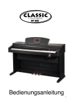
1
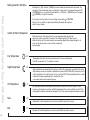
57640A 11/08 (DJU)
User Manual
WLM2 WLTA WLTD WLTP WLCT2
www.oj.dk
Congratulations
Congratulations with you new control system for
underfloor heating and cooling.
The control system has been developed to provide a
temperature control system for room heating and cooling,
integrating the switching of primary heating and cooling
sources with the control of water temperature and mixing
devices.
This ensures the best possible comfort conditions and also
reduces energy consumption.
Highlights of the system (depending on equipment):
:: Heating and cooling control for true comfort
:: Humidity sensor to prevent condensation on floors
:: Energy saving comfort with adaptive function
:: Area control for easy operation
:: Flexible installation for wired and wireless connection
:: Network communication for large applications
:: Easy installation with plug and lead connections
:: Optional weather compensation
BR-0965-A10
2
CONTENT
QUICKGUIDES
Quick guide analogue room sensors .............................................................. 4
Quick guide WLCT2 programmable Room controllers.................................... 4
Quick guide for Master modules...................................................................... 5
Trouble shooting . ............................................................................................ 6
INSTRUCTIONS
Master with Display Type WLM2................................................................... 7
Introduction...................................................................................................... 7
Supply Water Temperature Control.................................................................. 9
Using outdoor compensation module for weather compensation................... 9
Service Menu.................................................................................................. 11
Using cooling functions............................................................................... 13
Master Factory Settings................................................................................. 13
Error Indication............................................................................................. 15
Type WLCT2 (and WLCT2/R/HW/2)............................................................. 17
Introduction.................................................................................................... 17
Getting Started............................................................................................... 17
Daily Use of the room sensor......................................................................... 20
Programming 4-Event Clock Time and Temperature..................................... 21
Advanced Settings and Read-out.................................................................. 22
Reset to fatctory Settings - room controllers................................................. 26
Domestic hot water control............................................................................ 27
Radiator control.............................................................................................. 27
2 step heating................................................................................................. 27
Waterline Room sensors ............................................................................ 28
Setting of Room Temperature........................................................................ 28
Setting of Room sensor Operating Mode...................................................... 28
Zone Chart.................................................................................................... 32
3
increased or decreased by 4°C for that specific room.
If the WLTM-19 or WLTD-19 thermostat has been allocated to a clock controlled group, then when AUTOMATIC mode has been chosen with the built-in
Quickguides
slide switch, the temperature settings will be as programmed in the clock thermostat and not in the master, but the same local ±4°C adjustment is available.
On the Master WLM-1FS and WLM-3FS, if the temperature setting is changed, then the default temperature for all the rooms is changed, but the local
Quick guide analogue room sensors
adjustment can still increase or decrease this new setting by ±4°C. Turn the knob clockwise to increase the temperature.
These room sensors have an adjustment knob, which enables you to increase or decrease the room
Setting of thermostat operating mode
temperature setting by up to 4˚C.
1
2
Fig. 6
TA
TD
TM
Setting
of Thermostat
Operating
Mode have a slide switch for selecting the mode of operation of the
room
sensors
type WLTM-19
and WLTD-19
Thermostats
type
WLTM-19
and can
WLTD-19
have a Auto,
slide switch
(seeand
fig. 6)
for selecting the mode of
room
sensor. Four
different
modes
be selected:
Day, Night
OFF
operation of the thermostat. Four different modes can be selected: Auto, Day, Night and OFF.
Auto:Roomsensor
The thermostat
will follow
the temperature
settings
of master,
the master,
the thermostat
Auto:
will follow
the temperature
settings
of the
or if or
theif room
sensor
belongstotoana area
zonecontrolled
group using
will follow
follow the
the automatic
automatic sequence
belongs
by aa WLCT
WLCT2clock
roomthermostat,
controller, itit will
of temperatures
timings
set in the WLCT.
ofsequence
temperatures
and timings and
set in
the WLCT2.
Day:It Itwill
willcontrol
controlthe
theroom
roomtemperature
temperatureaccording
accordingtotothe
the(DAY)
(DAY)setting
settingdefined
definedininthe
themaster
master
Day:
(typically20˚C).
20°C).
(typically
Night:It Itwill
willcontrol
controlthe
theroom
roomtemperature
temperatureaccording
accordingtotothe
the(NIGHT)
(NIGHT)setting
settingdefined
definedininthe
the
Night:
master(typically
(typically15˚C).
15°C).
master
OFF:It Itwill
willcontrol
controlthe
theroom
roomtemperature
temperatureaccording
accordingtotothe
the(OFF)
(OFF)setting
settingdefined
definedininthe
themaster
master
OFF:
(typically5˚C).
5°C).
This
setting
intended
a ”frost
protection”
mode
and
used
if the
(typically
This
setting
is is
intended
toto
bebe
a ”frost
protection”
mode
and
is is
used
if the
room tounoccupied
be left unoccupied
long periods.
isroom
to be isleft
for longfor
periods.
WLTM-19
& WLTD-19
are are
recommended
for guest
rooms
andand
other
infrequently
used
rooms,
as WLTM-19
& WLTD-19
recommended
for guest
rooms
other
infrequently
used
rooms,
theyasthey
allow allow
simplesimple
override
of theof
automatic
timingtiming
sequence.
override
the automatic
sequence.
Quick guide Wlct2 programmable Room controllers
Mounting of limit sensor type WLTD and WLCT
Fig. 7
1
2
4
Jumper connected: max. limitation
Setting time and day
Limit Sensor
Thermostats
withday
a limit
sensor
haveroom
a mechanical
on the
If not already done by the installer, adjust
the time and
on any
WLCT2
controllerjumper
as follows:
printed circuit board allowing the limitation to be set for MIN. or
(picture with button positions)
MAX.
temperature
regulation.
If set
for MAX., it will have a
a. Using a pen or pencil press the small
pinhole
button with
the clock
symbol.
temperature
of 27°C.
b. Using the up and down buttons adjust
the hourssetting
and press
OK. Set for MIN., it has a setting of 17°C.
These
fixedOK.
when used with masters WLM-1BA
c. Using the up and down buttons adjust
thetemperature
minutes andare
press
or WLM-3BA
unless (1
the= thermostat
haspress
beenOK.
allocated to a zone
d. Using the up and down buttons adjust
the day number
Monday) and
group controlled by a WLCT clock thermostat. In this case, the
limit settings can be increased or decreased by accessing the
Setting areas
clock thermostat. The limits then set will apply to all relevant
thermostats with limit sensors belonging to that group. If the
If not already done by the installer, themaster
WLCT2WLM-1FS
room controller
can be is
used
to the
set the
times
or WLM-3FS
used,
limitoperating
settings can
beand
temperatures of room sensors (channels)
in addition
to controlling
its own buttons
room. on the master.
changed
through
the programming
To achieve this, do the following on the WLCT2 room controller:
a. Enter the “InFo” menu by pressing Mounting
the up andof
down
buttonsensor
simultaneously for 4 seconds.
limitation
b. Find the “ArEA” menu with the down
button
and presslimitation
OK.
Max.
temperature
is used to protect the floor area
c. The display shows “CH 1” (channelfrom
1). becoming too warm. This may be required if special floor
- Press OK button.
surfaces (real wood) are used. The sensor should be positioned
where it can read the true temperature of the floor and should
- Select “On” if this channel (room sensor) should be controlled by the WLCT2 room controller, or “OFF” if not.
- Now press OK button to get to the next channel (CH 2) and repeat this step until all required channels have been selected “On”.
d. After all channels are set up, find the “ESC” menu entry and press OK.
NB: If different times and temperatures are required for other channels (room sensors) within the system, more than one WLCT2 room controller can be
used. Care must be taken to ensure that the action of selecting a channel “On” is not made on more than one WLCT2 room controller.
3
Setting program times and temperatures
QUICKGUIDES
Adjusting the program times and temperatures.
On Monday to Friday (day 1-5), the CT room controller operates a 4-event program (wake, leave, return, sleep), and on Saturday and Sunday (day 6-7),
2-events (wake and sleep). Each event can have a separate temperature & time.
Each event is indicated on the display by the symbols (
)
To adjust these settings:
a. Press OK button for 5 seconds.
b. The display shows the wake up time for Monday to Friday.
c. To adjust the hours use the up and down buttons and press OK.
d. Now adjust the minutes using the up and down button and press OK.
e. Now adjust the desired wake up temperature using the up and down button and press OK.
f. Now repeat b to e for the leaving time and temperature, the return time and temperature and the sleep time and temperature.
g. Now repeat b to e for Saturday and Sunday wake and sleep times and temperatures.
NB: To set up different types of event programs, change to Fahrenheit scale, change to AM/PM clock or change of other advanced settings - please
refer to the section Instructions WLCT2.
Quick guide for Master modules
BA masters are pre set and need no adjustment - see “Factory settings” page 13
On the FS Master you can adjust the operating temperatures for any rooms which are not controlled
by a CT room sensor.
WLM2-1BA + WLM2-3BA
1
To adjust the day temperature (indicated by a sun in the display), press OK button.
Now use the up and down buttons to select the temperature required, and press OK button.
2
WLM2-1FS + WLM2-3FS
5
Setting day temperature
Setting remote night temperature
If a remote timer has been fitted by the installer, it is possible to automatically switch to a night
temperature.
To adjust the night temperature, press the up button until the moon is displayed and press OK button.
Now use the up and down buttons to select the temperature required, and press OK button.
Other advanced settings can be changed-See section “Master with display type WLM2”.
Trouble shooting
- If any LED is flashing on master - Please refer to section “Error indication”.
Room is too cold.
(After running for at least 48 hours)
1
QUICKGUIDES
2
3
4
5
6
Room is too hot.
(After running for at least 48 hours)
1
2
3
4
5
6
6
The room sensor is placed in a position that does not represent the general temperature in the
room. E.g. mounted on external wall or near an extraneous heat source
If the room is controlled by a WLCT2 room controller, check that the time and temperatures are
set correctly.
If the room sensor has got an override switch (WLTM or WLTD), the switch may be set in the “off”
or “night” position.
For rooms with floor sensors, the maximum floor limit setting could be preventing the room
reaching the desired temperature.
Insufficient heating capacity of the system.
Bad insulation creating large heat loss.
This could be caused by draughts within the wall cavities.
The room sensor is placed in a position that does not represent the general temperature in the
room.
If the room is controlled by a WLCT2 room sensor, check that the time and temperatures are set
correctly.
If the room sensor has got an override switch (WLTM or WLTD), the switch may be set in the “day”
position
For rooms with floor sensors, the minimum floor limit setting could be increasing the room
temperature above the desired setting.
Solar gain or extraneous heat source.
instructions
Master with Display Type WLM2
Introduction
WLM2-1BA - 3BA
WLM2-1FS -3FS
WLM2-1AO and WLM2-3AO
The masters type WLM2-1BA and
-3BA are pre-set and need no
adustment. See Master factory
settings page 11.
The masters type WLM2-1FS and
WLM2-3FS are provided with graphic
display to enable simple programming
and operations of the unit to be
achieved using simple and easy to
understand icons and symbols.
The ADD ON type WLM2-1AO
and WLM2-3AO is an extension
module for additional 6 outputs.
The module needs no adjustment
Using Clock thermostat (WLCT2-x9):
If a room controller is used as an area control for one room or a group of rooms, then all the room
sensors within this zone will operate according to the temperatures and times defined in the room
controller. However the local room sensors within the group are still capable of being adjusted by
± 4˚C so that some rooms can be set higher or lower than others. The decision as to which room
sensors will form part of the room controllers group is made by programming the room controller
(see instructions for WLCT2 unit). Any room sensors that are not part of the room controllers
group will operate to the temperature as defined in the master control, but again with the option of
local ±4˚C adjustment.
Using External Switch for Night Setback
The day temperature set point is defaulted to typically 21˚C and the night temperature to
typically 18˚C. These default settings can be changed on the FS master.
The current operating set point of the master can be changed from the day temperature into
night temperature, by connecting a separate timing device to the master. When the external
switch or timer is used to switch to night setback, this will override any time settings in a
WLCT2 room controller, including any room sensors that are part of a group allocated to that
room controller.
7
Moving Around in the Menu
Master with Display Type WLM2
8
By using the (△) (UP), and the (▽) (DOWN) you move through the main menu into sub menus. The
description of these submenus can be seen below. If a value needs to be changed, then press (✓)
(CONFIRM) button once, and alter the value with the (△) (UP) and (▽ ) (DOWN ) buttons. Then press
(✓) (CONFIRM) to accept the new value.
If you wish to reset the master to factory settings, then push the (✓) (CONFIRM)
button for 15 sec. until the 8 outputs starts blinking. The master has now been
reset to factory settings.
Control of Room Temperature
Day Temperature
21˚C
Night Temperature
18˚C
Off Temperature
5˚C
Max.
27˚C
Min.
17˚C
Within the memory of the master, there is a room temperature Setpoint which will
apply for all rooms connected to the system. This setting is typically 21˚C when the unit
leaves the factory, but it can be increased or decreased as required. Any change will apply to all
rooms on the system unless a room controller is employed
(see next para).
Temperature set point for all room sensors not part of a room controller group.
Push (✓) accept and (△) (▽) to adjust the set point.
When activated via an external timer, this action is valid for all room sensors connected to the master.
Night setback can also be activated on individual room sensors (WLTM & WLTD) by using the selector
switch and setting to the “night” position. A room controller (WLCT2) will automatically switch to night
setback at the times programmed into it, as will all the other
room sensors which are included in its group.
All room sensors with an override switch (WLTM & WLTD) can be set to an OFF position. This is
known as a frost protection position, and if the temperature in the room shoud fall as low as 5˚C, the
heating will be enabled to prevent frost damage. The 5˚C level can be changed in the master module.
Maximum Floor limit temperature for room sensors with limit sensor (floor sensor)
Minimum Floor limit temperature for room sensors with limit sensor (floor sensor)
Supply Water Temperature Control
Using supply water sensor for limitation of supply water:
Master with Display Type WLM2
9
A limit sensor should be used with the WLM2 1FS & WLM2 3FS, but can be used without the weather
compensation module (WLOC-19). In this case the master will control the supply water temperature
flowing into the system via the 3 or 4 port mixing valve and actuator. The factory default setting is
45˚C, but can be changed via the master display.*
Using outdoor compensation module for weather compensation
When the outdoor compensation module (WLOC) is connected to the system, the master calculates the correct supply water temperature,
taking into account the heat losses that will vary depending on the outdoor temperature, and the room temperature requirements of
the system. For example, on a day when the outdoor temperature is 12˚C, it is possible to run the heating system with a supply water
temperature of only 35˚C. this ensures economical running of the boilers, and comfortable room conditions throughout the year. The max
allowed supply water temperatur prevents excessive water temperatures if the outdoor temperature becomes extremely cold, e.g. - 30˚C.
55ºC
Max allowed supply water temperature. (This is a safety maximum)
-3ºC
Winter
Outdoor temperature
45ºC
Winter
Design supply water temperature at outdoor temperature –3°C
Design supply water temperature if used without outdoor compensation module.*)
Return
20ºC
Summer
Outdoor temperature
25ºC
Summer
Supply water temperature at outdoor temperature 25ºC
rding to the design
his is the safely
Master with Display Type WLM2
Max supply temperature
The max allowed supply water temperature is set according to the design requirements of the
installation (line A on the curve). This is the safely maximum.
design supply
at output, adjust
mfortable (we
ature at a time, and
Weather compensation
water temperature
e supply water
djustment of this
m to respond)
ne if an outdoor
door
wed supply water
10
Line 1: Factory settings
Line 2: Example on modified settings
Line 1: Factory settings
Line 2: Example on modified settings
Winter
A design outdoor temperature and the corresponding design supply
water temperature are set (point B). To increase the heat output, adjust
the supply water temperature higher, until you feel comfortable (we
recommend only a 2 degree adjustment of this temperature at a time, and
time allowed for the system to respond).
Summer
An outdoor temperature and the corresponding supply water temperature
are set (point C). Set the outdoor temperature at the level where heating will no longer be
required (this is known as the summer shut down temperature) Default setting is 20˚C.
Then set the supply water temperature that you require when the outside temperature is at
20˚C. The default is 25˚C.
To start the summer shut down at a lower temperature level, reduce the outdoor temperature setting, and/or reduce the supply water temperature at this setting.
The master calculates the supply water temperature on the line C to 1 if an outdoor design temperature of -3˚C is selected, or on the line C to 2 if the outdoor is selected at -10˚C. The intersection point on the line of the actual outdoor temperature indicates the calculated supply water temperature.
Compensation for outdoor temperature can only be done if an outdoor compensation module (WLOC) is installed. Without outdoor compensation module the Master will adjust the supply temperature after the design supply water temperature winter setpoint (default 45°C).
Service Menu
Master with Display Type WLM2
11
55ºC
Service menu
Push accept to enter
The controller will automatically return to main menu after 30 minutes.
2.0
Software version
OK no failures
E0 to E11 if a failure is present. See page 13 for explanation.
LS= Low signal on wireless room sensors/controllers
LB= Low battery on wireless room sensors/controllers
Push accept to enter and see which unit has the failure
TOTAL X
Submenu 2
Submenu 2a
Network Status (normally hidden)
If a network master detects a network this menu entry is shown.
Here it is possible to check the status of the network.
“TOTAL X”:
Shows how many masters the network master detects.
(x is the amount of connected masters)
“NET OK”
No errors detected in the network
“ERROR ON IDxx” Shows if any of the attached masters has local errors.
(IDxx tells which master it concerns. The ID number is
what the encoder on the master is set to)
“NET ERROR”
Tells that one or more masters on the network has
stopped communicating. Please use the menu entry
below to check which masters it concerns
Push accept to enter and see which master it is that has the error and what error it is.
Using the “up” and “down” button, select which masters status should be shown on the right side of the display.
>ID11 - ?
ID12 - ?
ID21 - ?
E:CHANNEL
Possible Errors:
“LOADING STATUS...” :Receiving information from the network.
“STATUS OK”:
No errors detected
“NET-COMM ERROR” : Communication is missing to that master. Please check the connection or remove the master from memory with a hard reset.
“E1-E11”:
The same errors as shown in section “Error Indication” under “Flashing Power LED”
“E:CHANNEL”: This is a channel error which has to be checked locally on that master.
Master with Display Type WLM2
12
-2.4°C
⇄
49.2ºC
39.2ºC
44.4ºC
Read-out
Outdoor temperature
Read-out
Actual supply water temperature
Actual application sensor temperature
Read-out
Calculated setpoint by the controller for the supply water temperature
Push accept for 3 sec. to change PI-action & 0-10V out
3.5V
Read-out
Control signal for the mixing valve.
At 10 V the mixing valve is fully open (unless the output setting has been changed to 10-0, in which case at
10 V, the valve will be fully closed)
--24.0°C
22.9°C
Read-out
Room temperature in the different rooms. Push accept (✓), and the up and down keys to select another
room. The actual room temperature is shown in the centre of the display. If a maximum limitation sensor
is connected the measured temperature is shown above the room temperature, and if a minimum limitation
sensor is connected, the temperature is shown below.
Return
instructions
Using cooling functions
If the installation is capable of doing cooling, a WLAC-1 switching module is installed.
To enable cooling, switch the slider on the right hand side to the cooling position.
The system now switches into cooling with a set point than is 3˚C above the master day set point.
(In case the WLAC-1 module is connected to a BMS controlled signal, the BMS system will make the decision when to
switch to cooling – please leave the slider on the WLAC-1 in position heat).
•
•
•
By using a humidity sensor the system limits the formation of condensation on floor surfaces due to high humidity.
If a dehumidifier is being used it will activate if high humidity limits the cooling function.
When cooling is enabled the cooling set point will be pre-determined by the master
and will override any settings in any clock thermostat to ensure optimum energy efficiency.
Master Factory Settings
Master
BA/FS
FS
13
Settings
Factory setting
House temperature
21˚C
Night temperature
18˚C
Off temperature
5˚C
Floor Limit temp high
27˚C
Floor Limit temp low
17˚C
Max water temperature
55˚C
Weather compensation
Outdoor temperature
-3˚C
Cold (winter)
Water temperature
45˚C
Weather compensation
Outdoor temperature
20˚C
Warm (summer)
Water temperature
25˚C
Own settings
Additional information
Using cooling functions
14
Master
Settings
BA/FS
Cooling mode
Factory settings
Day cooling temperature
Day heat temperature + 3°C
Night cooling temperature
Day cooling temperature + 3°C
DEW point safety zone
DEW point + 3°C
Room temperature control
PI - control
P = 4°C
I = 90-180 sec
K-factor = 0.1
Floor Limit temperature control
P - control
P = 4°C
Adaptive PWM control
Max allowed Room temperature fluctuation
+/- 0.5°C
Self adjusting (adaptive) PWM time interval limits
15 – 45 minutes
Max number of connected
sensors
Wired and wireless
24
Sensor timeouts
Wired
300 sec.
Wireless
10000 sec. (2h 45 min)
Minimum cooling supply water temperature
16°C
PI - control
P = 20°C
I = 300 sec.
K-factor = 0.05
FS
Supply water temperature
control
(5 min)
Error Indication
During normal operation the power LED will be ON when the master control is energised. The red output Channel LED’s
(1 to 8 on the master, and 9 to 14 on the add-on module) will indicate if the channel output relay is ON/OFF.
An error / fault message is shown by flashing the power LED or one of the red output Channel LED’s. From the number of flashes
on any one LED, the problem can be diagnosed, and identified from the following:
The error number will be indicated by the number of flashes, with a pause of less than a 1/2 second between the flashes. The indication will be followed by a
pause of 2 seconds, following which the sequence will be repeated. The failure code can also be seen in the service menu on WLM2-FS MASTERS (submenu 2).
Flashing Power LED (Red and green)
Communication to the network has errors. On the network master it tells that one or more masters are not communicating. On a network slave it tells that
communication to the network master is missing.
Flashing Power LED (Red)
E1, 1 flash
One or more room sensors, room controllers, WLH, WLAC that are set to channel 0 or channel 15 are no longer sending data to the master control. The fault is corrected by replacing the room sensor. The master will need to be HARD RESET (see next page “HARD RESET”)
(NOTE: If the room sensor is of the WIRELESS type, the error/fault message could be an indication that the power has failed,
and that the internal battery of the room sensor needs to be replaced)
E2, 2 flashes
One or more room sensors have been set to a channel number which does not exist in the system. For example, the message will occur if the units are set to channels 9-14 and the required add on (AO) module are not found in the system. The error is corrected by setting the channel number of the room sensor to a channel that does exist within the installed master/add on module system.
E3, 3 flashes
Application sensor defect. The fault is corrected by changing the temperature sensor. If the sensor has been removed deliberately to
change the operation of the system, follow the HARD RESET instruction below.
E4, 4 flashes The outdoor compensation module (WLOC) is defective. The fault is corrected by changing the outdoor compensation module.
If the module has been removed deliberately to change the operation of the system, follow the HARD RESET instruction below.
E5, 5 flashes
The external Supply limit sensor (type ETF-1899A) is defective. The fault is corrected by changing the temperature sensor. If the
sensor has been removed deliberately to change the operation of the system, follow the HARD RESET instruction below.
E6, 6 flashes
E7, 7 flashes
Internal overheating. The master has its own internal safety temperature protection system. The problem is corrected by improving the ventilation around the master module.
E8, 8 flashes
The communication to the AO module has been lost. The fault is corrected by re-establishing the connection to the AO module or by changing the AO module if it is defective - or if it has been deliberately removed, with a HARD RESET.
E9, 9 flashes
Indicates total number of input units exceeded. Please refer to factory or your local service engineer.
Defective internal overheat sensor. The Master will control as normal, however the protection against internal over heating is no
longer active. The fault can only be corrected by replacing the master module.
E10, 10 flashes No connection to wireless receiver, type WLRC2-19.
E11, 11 flashes Step 2 on 2-step controller (WLCT2-X9/2) is used by another room sensor/controller.
15
Only one error/fault condition can be shown at a time. If more than one error occurs, they will be prioritised in the shown sequence (E1, 2, 3…).
Flashing output LED (red):
The appropriate output channel LED can flash, indicating that the room sensor or room contoller on that channel has a fault/error. The failure code can
also be seen in the service menu (submenu 2a).
Error Indication
E1, 1 flash
The master has lost communication to the room sensor. The fault is corrected by re-establishing the connection to the Room
Sensor and the fault condition will be automatically reset once correct communication is resumed. If the room sensor is
defective and has to be changed, or if it has been deliberately removed, it is necessary to make a HARD RESET. (NOTE: If the
room sensor is of the WIRELESS type, the error/fault message could be an indication that the power has failed, and that the
internal battery of the room sensor needs to be replaced)
E2, 2 flashes
The internal sensor in the room sensor/controller is defective. The fault can only be corrected by replacing the room sensor/
Controller. Remember to make a HARD RESET after installing the new room sensor/controller.
E3, 3 flashes
The limit sensor on the room sensor/controller is defective. Replace the faulty sensor. Reset is NOT required.
E4, 4 flashes
Defective WLCT2 room controller. If a room controller operating a group of room sensors becomes defective, the remaining
room sensors will continue control within the maximum and minimum limits programmed into the Room controller.
E5, 5 flashes
Two or more room controllers are trying to control this output. Check “AREA” setting on the room controllers.
E6, 6 flashes
Channel output number one is configured as a dehumidifier output, error caused by a room sensor/controller also being set to control this output.
RESET
There are 2 different reset actions that can be used.
HARD RESET
If the ‘✓’ button is pressed for 5 seconds, a HARD RESET will be initiated. (Indicated by all the red output LED’s(1-8) lighting in sequence). This reset
will remove from the system any room sensor unit with a defective input sensor, or a defective AO module. The fault message will be reset but the
defective items will no longer participate in the system. To add or replace a new unit, please refer to “Replacing equipment - Replacing a faulty sensor/
controller”. To erase the identity of the defective component from the master memory a HARD RESET must be performed Hard resets do not alter the
temperature settings already programmed into the master control.
FACTORY RESET
If the (√ ) button is pressed for more than 15 seconds, a total factory reset will be initiated. This is indicated through flashes of channel LEDs 1,3, 5 and
7 alternating with channel LEDs 2, 4, 6 and 8 (while the “√” button is pressed).
A factory reset will put all programmed temperature settings back to the factory defaults. It will also remove all room sensors/Controllers from the
master memory, and reset the system to accept only those room sensors/Controllers that are functioning correctly.
To reconnect room sensors/controllers, please refer to “Replacing equipment - Replacing a faulty sensor/controller”.
16
instructions
ANUAL
NType
UUASWLCT2
LE R M
(and WLCT2/R/HW/2)
Type WLCT
Introduction
57541 09/04 - (BJ)
The room controller type WLCT2-x9 is a 4 event programmable controller used to control underfloor heating areas
or special features on the WLM2 installation. The standard WLCT2-x9 can be used to programme up to 4 time and
temperature events over a 24 hour period, based upon a 7 day setting. Once a WLCT2-x9 has been fitted the times and
temperatures for the area(s) it controls will no longer come from the defaults set in the main WLM2 master.
Introduction
The clock thermostat type WLCT is part ofInthe
underfloor
system
WLM. set,
Thewithin
thermostat
can be setand
to control
one
room, setting
or it can
be set within its
addition
to theheating
immediate
areatype
of control
the WLCT2-x9,
selected
viasingle
the ‘AREA’
contained
a master
to control aheating
group of
thermostats
/ rooms/zones.
LCT is as
part
of the underfloor
system
type
WLM.
The thermostat
cancan
be set
to control
one
single
room, orcharacteristics
it can be set of other sensor (up to 14) fitted to the WLM2
internal
menu,
the WLCT2-x9
control
the time
and
temperature
All the thermostats
that are part of that group will follow the times and temperatures programmed into the clock thermostat. For example, if the temperature
p of thermostats
/ rooms/zones.
master, this has been designed to maximise comfort and efficiency and promote energy saving and associated cost savings.
programmed
the clock
thermostat
is 22°C, all the
thermostats into
/ rooms
belonging
to that group
will then ifalso
controlled at 22°C. Depending on the
art of that
group willinfollow
the times
and temperatures
programmed
the clock
thermostat.
For example,
thebe
temperature
types
of
thermostats
used
you
can
adjust
the temperature
+ or -4°C
in different
rooms,
giving
a22°C.
possible
room setpoint
+18 to +26°C.
mostat is 22°C, all the thermostats / rooms belonging
to
that
group
will
then
also
be
controlled
at
Depending
on
theof
Where the WLCT2-x9 is controlling other areas the +/- 4°C setting of those
areas will now operate from the WLCT2-x9
u can adjust the temperature + or -4°C in different
rooms,
giving
a
possible
room
setpoint
of
+18
to
+26°C.
A WLCT2-x9
is set to
22°Cthe
andday
hasallowing
been given
over ‘Area
1’, times
the WLTA-x9
The clock thermostat can be programmedsettings,
to work e.g.
at different
temperatures
during
lowercontrol
temperatures
during
that the fitted
room in
is ‘Area 1’ now has
a control
rangecosts
of 18°C(-4°C)
to 24°Cthe
(+4°C).
unoccupied.
Lower
temperatures
will lower
your energy
without
reducing
comfort.
Alltimes
thermostats
that
areispart of the group will follow any new
programmed
to work
at different
temperatures
during
the
day
allowing
lower
temperatures
during
that
the
room
In addition
to the standard WLCT2-x9 room controller, you may have fitted to your system one of the following;
time
or temperatures
programmed
the clock
thermostat.
ures will
lower
your energy costs
without in
reducing
the
comfort. All thermostats that are part of the group will follow any new
mmed in the clock thermostat.
This control
theinstallations.
operation of a secondary heat source, for a specific area, as a boost function When it leaves the factory, the thermostatWLCT2-x9/2:
has a preset program
suitableallows
for most
define the thermostats
operating
in conjunction
with
the underfloor
heating.
You only need to set the clock and day, and
/ rooms
that should
belong
to the group.
e thermostat has a preset program suitable for WLCT2-x9/R:
most installations.
This control is used for the control of radiators in a domestic central heating circuit.
k and day, and define the thermostats / rooms WLCT2-x9/HW:
that should belong
to control
the group.
This
is used
the production
of hottowater
control
within aThese
system.
The thermostat has a pin button marked R (see fig. 1), allowing
you, at any
time,for
to reset
the thermostat
the factory
settings.
are listed at the end of
Upon installation your installer should have set up the WLCT2-x9 control to suit your needs, should you this manual with space for you to record your
own weekly schedule.
on marked R (see fig. 1), allowing you, at any time,
to
reset
the
thermostat
to
the
factory
settings.
These
are
listed
at
the
end
of
need to change any of the setting please follow the instruction detailed in following pages.
u to record your own weekly schedule.
The WLCT2-x9: can be reset by pressing the button marked ‘R’ (see fig 1), this will allow you to return to the factory settings at any time. The default factory settings are detailed after the WLCT2-x9 programming section of this manual.
1. Getting started
Display symbols
Fig. 1 - Buttons
Getting Started
Fig. 1
Display symbols
Buttons
A:
B:
C:
Display
G
Adjustment
down
OK accept
E:
F:
G
H
J
17
HK
D:
Adjustment
up
ResetJto
factory
setting
Pin button
adjust of
clock
I
K
Display symbols
Display
Type WLCT2 (and WLCT2/R/HW/2)
G
K
ns to select
ton18( ).
H:
I:
Automatic
mode
Manual
mode
Time and
temperature
J:
K:
Day number
4-event symbol
H
J
I
G:
Automatic
Setting
mode
H:
Wake
Out
Night
Home
I:
Manual
the
room
mode
Time and
controller
into
temperature
operation
First time power is connected the clock and day will be flashing and must be set. If you need to adjust the
time of the thermostat at a later date, insert a pin into the hole marked
(see fig. 1) for setting of time and
day. Adjustment should be made for change in summer and winter time.
J:
K:
Day number
4-event symbol
Out
Wake
and must be set. If you need to
he hole marked
(see fig. 1)
ge in summer and winter time.
ns to select
n ( ).
G:
Night
Home
Press the UP (△) or DOWN (▽) buttons to select
the correct hours and press OK button ( ).
Press the UP (△) or DOWN (▽) buttons to select
the correct minutes and press OK button ( ).
Then press the UP (△) or DOWN (▽) button to
select the correct day and press OK ( ) button.
AREA SETUP - see next page.
1-7
Type WLCT2 (and WLCT2/R/HW/2)
19
ArEA - (Group of rooms)
The rooms that are to be set as part of the WLCT2 area will follow the temperature settings of the room controller example, an area could
be the living room, kitchen, and children’s rooms, having a high room temperature requirement during afternoon and early evening, and
a lower temperature during the early part of the day and at night. Each room sensor will have a channel number, designated CH1, CH2
etc. The appropriate channel number of any room sensor is determined by the numbered output on the master control which is actually
switching the valve/actuator for that area.
For example, a system may have the kitchen room sensor operating master output # 4, and the childrens room sensor operating master
output #5. If the WLCT2 room controller is then situated in the living room, and operating output #1, then the WLCT2 need be programmed
to control outputs 1, 4, & 5. (Each room sensor will have been set to operate its appropriate output ch see separate instructions).
To do this, enter the ArEA sub menu., and press OK ( ) button. CH 1 will be displayed; use the OK ( ) button and then the UP (△) button
to change the setting to ON. Press OK ( ) and CH 2 is displayed. Use the UP (△) button until CH4 is displayed, press OK ( ), and change
to ON. Repeat this for CH 5. All three room sensors will now operate under the control of the WLCT2 room controller.
In total up to 14 Channels can be programmed in this way, and it is possible to have more than a single room controller, each own sub
room sensors operating to its schedule and temperatures.
Set the Channels / Rooms (Ch) to ON if they should follow the settings
of this clock thermostat.
In total 14 channels / rooms can be controlled.
Daily Use of the room sensor
4-Event Clock Mode
Type WLCT2 (and WLCT2/R/HW/2)
Wake up
Leave
home
Sleep
20
The day has been split into 4 events describing a typical day. When the room sensor is in
this 4-event mode it will change the temperature to the required level automatically at the
programmed times. As standard the room controller has days 1 to 5 (Monday to Friday)
with 4 events and days 6 and 7 (Saturday and Sunday) with 2 events. Each events allows
you to increase or decrease the set temperature. For programming see page 17.
Please, see page 18 - PRO - 4-event sequence to alter the daily event sequence.
Return
4-event clock mode/
automatic mode:
Comfort mode:
5 secs.
In automatic mode, the clock function symbol (
indicated. Programming page 17.
) will be
Temporary override
To temporarily override any temperature in the 4-event schedule program, press the UP (△) button once, to show
the temperature in the display, and press UP (△) or DOWN (▽) again to increase or decrease the temperature. The
display will flash for 5 seconds, and will then revert to the time. The override will operate until the next programmed
event when the thermostat will resume the automatic programme.
Cancel comfort mode (temporary override)
To cancel the temporary override, press the OK (
Manual mode:
) and one of the 4-event symbols (
) button twice.
Permanent override:
During holidays, the scheduled 4-event program can be overridden. Press the OK ( ) button, and then the UP (△) or
DOWN (▽) button until the override temperature is set. The set temperature will remain in the display and the unit will
now operate to this temperature permanently.
Cancel manual mode
To cancel the permanent override state press the OK (
) button once, and the unit will resume automatic function.
Programming 4-Event Clock Time and Temperature
Type WLCT2 (and WLCT2/R/HW/2)
21
For each event, the start time and required temperature needs
to be set.
For example, in the morning you wish the heating to start at
07:00 and the temperature to rise to 25˚C. Press OK ( ) button
for 3 seconds and the start time is displayed. Change this to
07:00 with the UP (△) or DOWN (▽) button. Press OK ( ) to
confirm.
The temperature is now displayed. Change this to 25˚C with the
UP (△) or DOWN (▽) button. Press OK ( ) button to confirm.
This action can now be repeated for the second, third and
fourth event.
Press OK (
Day 1 - 5
: Time and temperature
: Time and temperature
These settings will be valid for days 1-5 showing on the display.
To program the days 6 and 7, repeat the above. Days 6 and 7
are usually Saturday and Sunday, and only have two events
(generally morning ON and evening OFF).
The temperature can be set within the range of +5 to +35˚C.
It is also possible to select the heating OFF at that event by
reducing the setting to 5˚C, and then pressing the (▽) once
more.
Note that when programming the “Sleep” time (event 4),
please ensure that this time is before midnight (00:00).
) button for 3 secs. to begin programming
: Time and temperature
: Time and temperature
Day 6 - 7
: Time and temperature
: Time and temperature
Advanced Settings and Read-out
Type WLCT2 (and WLCT2/R/HW/2)
Press both UP (△) and DOWN (▽) buttons together for 3 seconds. INFO is displayed.
Continue pressing the UP(△) button until you reach one of the desired sub menus, PRO, Hi Li, Scal, and ArEA (For explanations, see
below. Select the sub menu with the OK ( ) button.
INFO - Information
The values of the actual measured room temperature and the floor temperature can be seen.
The floor temperature is only shown if a floor sensor is installed.
Press UP (△) or DOWN (▽) button to show the different readouts.
Software version
Room temperature
No changes can be made here. Use the OK ( ) button to end.
Floor temperature
PRO - 4-event sequence
It is possible to change the factory event sequence of Days 1-5 - 4 event, and days 6 & 7 – 2 event. Days 1 to 5 are usually Monday to
Friday, whilst days 6 & 7 are usually Saturday & Sunday. An EVENT is either an ON or an OFF operation. You can select from the following
sequences which are displayed in the form of a code.
4 events 5 days, 2 events 2 days
indicated by Code 4:52
4 events 6 days, 2 events 1 days
indicated by Code 4:61
4 events 7 days
indicated by Code 4:70
2 events 7 days
indicated by Code 2:70
2 events 5 days, 2 event 2 days
indicated by Code 2:52
Select the required sequence with the OK (
22
) button.
Type WLCT2 (and WLCT2/R/HW/2)
23
Hi Li - Floor sensor. Max and min allowed temperature of the floor surface
A limit sensor can be connected to the room controller.
Max limitation is used for safety to prevent high floor temperatures. For example wooden floor constructions which should not
be allowed to exceed a maximum of 27˚C. The value can be set from 5˚C up to 55˚C. The value can also be set to OFF (adjust the
temperature to 55˚C and push button up once more).
Low limitation is used where the temperature of the floor is required never to fall below the minimum set temperature. Example in
kitchens or bathrooms with tiles. The value can be set from 5˚C up to 55˚C. The value can also be set to OFF (adjust the temperature to
5˚C and push button down once more). Remember the max limit temperature must be set higher than the min limit temperature.
The limit temperatures defined in the room controller will be valid for all the room sensors with limit sensor (type WLTD-19) which are part
of the area allocated to the WLCT2 unit.
The maximum allowable floor temperature setting is shown. Use
the UP (△) or DOWN (▽) button to increase or reduce, and OK ( )
button to accept.
The display will now show LoLi. Press OK ( ) button to continue.
The minimum allowable floor temperature setting. Use the UP (△)
or DOWN (▽) button to increase or reduce and OK ( ) button to
accept.
SCAL - Time and temperature scale selection
You can select either ˚C or ˚F scale, and 12 or 24 hour clock as
follows:
Press UP (△) or DOWN (▽) button to change settings. Confirm the
required scale with the OK button ( ) button.
ArEA - (Group of rooms)
The rooms that are to be set as part of the WLCT2 area will follow the temperature settings of the room controller example, an area could
be the living room, kitchen, and children’s rooms, having a high room temperature requirement during afternoon and early evening, and
a lower temperature during the early part of the day and at night. Each room sensor will have a channel number, designated CH1, CH2
etc. The appropriate channel number of any room sensor is determined by the numbered output on the master control which is actually
switching the valve/actuator for that area.
For example, a system may have the kitchen room sensor operating master output # 4, and the childrens room sensor operating
master output #5. If the WLCT2 room controller is then situated in the living room, and operating output #1, then the WLCT2 need
be programmed to control outputs 1, 4, & 5. (Each room sensor will have been set to operate its appropriate output ch see separate
instructions).
To do this, enter the ArEA sub menu., and press OK ( ) button. CH 1 will be displayed; use the OK ( ) button and then the UP (△) button
to change the setting to ON. Press OK ( ) and CH 2 is displayed. Use the UP (△) button until CH4 is displayed, press OK ( ), and change
to ON. Repeat this for CH 5. All three room sensors will now operate under the control of the WLCT2 room controller.
In total up to 14 Channels can be programmed in this way, and it is possible to have more than a single room controller, each own sub
room sensors operating to its schedule and temperatures.
Type WLCT2 (and WLCT2/R/HW/2)
Set the Channels / Rooms (Ch) to ON if they should follow the settings
of this clock thermostat.
In total 14 channels / rooms can be controlled.
2 st
This menu is only visible on 2 step controllers (WLCT2-x9/2)
2 step – Change of values in 2 step function.
ON
OFF
The display will now show TEMP. Press OK ( ) to continue.
tEn
P
3.0°C
Use the UP (△) or DOWN (▽) button to change the temperature
setpoint in the 2-step function.
( If the actual room temperature is higher than the setpoint minus this
setting, the second output will not be activated)
The display will now show TEMP. Press OK ( ) to continue.
tInE
00:01
24
Press the DOWN (▽) button to activate or de-activate the 2 step
function.
Press OK ( ) to confirm.
Use the UP (△) or DOWN (▽) button to change the time (in minutes)
before step 2 is activated.
(This parameter decides how long the actual temperature is allowed to
remain below the setpoint minus the TEMP setting before the second
output is activated)
Adaptive function
This function enables the thermostat to calculate when it needs to switch ON so that the required temperature is reached at the set time.
With a start time of 07:00 therefore, the thermostat may switch ON as early as 06:00 so that the desired temperature of 2 5˚C is achieved
by 07:00. Without this function set, the thermostat will start to heat at the time you set.
Type WLCT2 (and WLCT2/R/HW/2)
25
Press the DOWN (▽) button to switch between on and off.
Press OK ( ) button to confirm.
ESC - Escape
Press OK ( ) button to end programming and to return to scheduled
programme.
Reset to fatctory Settings - room controllers
NOTE: If more than one WLCT2 is present on the system, please copy this page.
Type WLCT2 (and WLCT2/R/HW/2)
26
Press the pin button R for 3 secs. and the thermostat returns to
factory settings.
Remember to set time, day and area.
Group
4-event time and temperature
Own settings
Standard
WLCT2-x9
Special
WLCT2-x9/R
Special
WLCT2-x9/2
Special
WLCT2-9/HW
Time
Temperature
Temperature
Temperature
Temperature
06:00
21˚C
21˚C
21˚C
50˚C
08:00
19˚C
19˚C
19˚C
30˚C
16:00
22˚C
22˚C
22˚C
50˚C
22:30
17˚C
17˚C
17˚C
30˚C
08:00
22˚C
22˚C
22˚C
50˚C
23:00
17˚C
17˚C
17˚C
30˚C
Day 1-5
Day 6-7
Other settings
4-event sequence
-
4:52
4:52
4:52
4:52
-
27˚C
-
27˚C
-
17˚C
17˚C
-
17˚C
-
2-step time
-
-
-
60 min
-
2-step temperature
difference
-
-
-
2˚C
-
High floor limit
temperature
Low floor limit
temperature
Special settings
Time
Temperature
Room
Ch 1
Off
Ch 2
Off
Ch 3
Off
Ch 4
Off
Ch 5
Off
Ch 6
Off
Ch 7
Off
Ch 8
Off
Ch 9
Off
Ch 10
Off
Ch 11
Off
Ch 12
Off
Ch 13
Off
Ch 14
Off
Example
Ch 1
Kitchen
On
Ch 2
Living room
On
Insert the room name in the box
against each Ch number, and add ON
if it is controlled by a clock thermostat.
Domestic hot water control
Type WLCT2 (and WLCT2/R/HW/2)
27
It is possible to control the domestic hot water temperature with a special version of the WLCT2, called
WLCT2-X9/HW) to ensure optimum energy saving.
A hot water sensor is connected to the controller and measures the temperature in the storage cylinder.
•
•
To change the temperature of the domestic hot water, just change the set point in
the WLCT2-X9/HW by using the up or down button.
The 4-event system in the WLCT2-X9/HW can be used to save energy when hot water
is not needed..
WLCT2/HW
Radiator control
It is possible to control a radiator circuit room temperature with a special version of the WLCT2 called
a WLCT2-X9/R) to ensure optimum energy saving.
The controller measures the temperature in the room, and a zone valve is then controlled via the WLM2
master, which in turn activates the boiler on demand.
• To change the temperature of the radiator circuit , just change the set point in the WLCT2-X9/R
by using the up or down button.
• The 4-event system in the WLCT2-X9/R can be used to save energy when heat is not needed.
WLCT2/R
2 step heating
A special version of the WLCT2 called WLCT2-X9/2 is capable of controlling an additional heat source
in a room. In addition to the primary under floor heating output, the room controller is now able to
control a second output as a boost function, which will be activated only if the temperature cannot be
achieved by the primary under floor heating output within a preset time period.
The Room Controller is used as a standard WLCT2.
If required the settings for when the second heating output is needed can be changed in the service
menu in the WLCT2-X9/2.
WLCT2/2
An additional Menu entry “2 st” can be found.
In this menu two parameters can be changed:
Temp: Time: If the actual room temperature is higher than the setpoint minus this setting, the second output will not be activated.
This parameter decides how long the actual temperature is allowed to remain below the setpoint minus the TEMP setting before the second output is activated.
instructions
Waterline Room sensors
Setting of Room Temperature
If the WLTM-x9 or WLTD-x9 Room sensor has been allocated to a WLCT2 controlled area, then when AUTOMATIC mode has been chosen
with the built-in slide switch, the temperature settings will be as programmed in the WLCT2 Room controller and not in the master, but the
same local ±4°C adjustment is available.
On the Master WLM2-1FS and WLM2-3FS, if the temperature setting is changed, then the default temperature for all the rooms is changed,
but each WLTA, WLTM or WLTD Room sensor is locally adjustable with its own adjustment knob. With this knob the temperature setting
from the Master can be increased or decreased by 4°C for that specific room.
The master is supplied with default temperature settings which are used by all non Room sensors that are connected to the system. In
Master WLM2-1BA & WLM2-3BA, the DAY temperature setting is fixed at 21°C and the NIGHT temperature is fixed at 15°C.
In Master WLM2-1FS & WLM2-3FS, the DAY, NIGHT and OFF default temperatures are adjustable through the display.
Automatic switching between DAY and NIGHT temperatures is done by either connecting a separate timing device to the master, or using a
WLCT2 Room controller and allocating other Room sensors as part of its group. It is possible to have two or more Room controllers in the
system, with each one having its own group of non Room controllers.
Setting of Room sensor Operating Mode
Fig. 3
Room sensors type WLTM-x9 and WLTD-x9 have a slide switch (see fig. 4) for selecting the mode of
operation of the controller. Four different modes can be selected: Auto, Day, Night and OFF.
Auto: The controller will follow the temperature settings of the master, or if the Room sensors
belongs to a zone group using a WLCT2 Room controller, it will follow the automatic sequence of
temperatures and timings set in the WLCT2.
Day: It will control the room temperature according to the (DAY) setting defined in the master
(typically 21°C).
Night: It will control the room temperature according to the (NIGHT) setting defined in the master
(typically 17°C).
OFF: It will control the room temperature according to the (OFF) setting defined in the master
(typically 5°C). This setting is intended to be a ”frost protection” mode and is used if the room is
to be left unoccupied for long periods.
WLTM-x9 & WLTD-x9 are recommended for guest rooms and other infrequently used rooms, as they
allow simple override of the automatic timing sequence.
28
29
30
OJ Electronics A/S
OJ Electronics UK
OJ ELECTRONICS A/S
Stenager 13B
crusader park
c/o Robert Bielecki
DK-6400 Sønderborg
warminster
UL. BRZOZOWA 4
Denmark
wiltshire, ba12 8sp
58-160 SWIEBODZICE
united kingdom
POLAND
t.+45 73 12 13 14
t.+44 01985 213 003
T. +48 4220 91 742
F.+45 73 12 13 13
F.+44 01985 213 310
F. +48 4220 91 744
[email protected]
[email protected]
[email protected]
www.oj.dk
www.ojUK.co.uk
www.ojelectronics.pl
Zone Chart
Example
NB
1
CH 1
Thermo heads / Output
Thermostat
Zone
Kitchen
3 loops marked 1, 2 and 3
W adjustment
and MIN limit sensor
The following chart enables you to write down the zone name, the number of loops serving it, and the control
thermostat type. PLEASE LEAVE THIS INSTRUCTION WITH THE CLIENT.
Special function
CH F
14
CH E
13
CH D
12
CH C
11
CH B
10
CH A
9
CH 9
8
CH 8
7
CH 7
6
CH 6
5
CH 5
4
CH 4
3
CH 3
2
CH 2
1
CH 1
Thermo heads / Output
Thermostats
Zone
Water loops
Thermostats
None
5 7 6 4 0 A