1
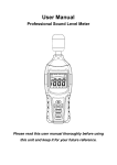
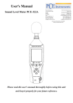
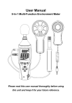
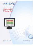
User Manual
Professional Sound Level Meter
Please read this user manual thoroughly before using
this unit and keep it for your future reference.
Contents
1. Safety .................................................................. 1
2. Introduction .......................................................... 2
3. Specifications ...................................................... 3
4. Meter description ................................................. 5
5. LCD display description ...................................... 7
6. Operation instructions ......................................... 8
7. Calibration ......................................................... 14
8. Basic operation.................................................. 14
9. Operating procedures ....................................... 16
10. Software installation ........................................ 17
11. Software interface introduction ........................ 18
12. Operation ......................................................... 24
13. Notes ............................................................... 26
14. Accessories ..................................................... 27
1.
Safety
Read the following safety information carefully before
attempting to operate the meter.
Use the meter only as specified in this manual; otherwise,
the warranty may be invalidated.
◆Environment conditions:
Altitude up to 2000 meters
RH≤90%(Non-Condensation)
Operating Temperature: -20~60℃
◆Maintenance
Repairs or servicing should only be performed by ATP
Instrumentation Ltd.
Wipe the unit with a dry soft cloth. Do not use abrasives or
solvents on this instrument.
◆Safety Symbol
Complies with EMC
1
2. Introduction
This Sound Level Meter is designed to meet the
measurement requirements of safety engineers, health,
industrial safety officers and sound quality control in various
environments like construction sites, factories, schools,
offices, traffic access, households, studios etc.
◆ Complies with IEC61672-1 CLASS2 standard
◆ Max/Min record
◆ Over range indication
◆ Under range indication
◆ Time, data transmission display
◆ A & C Weighting
◆ Selectable response time: FAST/SLOW
◆ Analog AC/DC outputs for connection to frequency
analyser or X-Y shaft recorder
◆ PC real-time monitoring, recording and memory
◆ 4 digit LCD display with a resolution of 0.1dB
◆ Sampling time: 2 times per second.
2
3. Specifications
Applied standard
IEC61672-1 CLASS2
Accuracy
±1.4dB
Frequency range
31.5Hz to 8,000Hz
Dynamic range
50dB
Lo:
30dB~80dB
Measuring level
Med:
50dB~100dB
range
Hi:
80dB~130dB
Auto: 30dB~130dB
Frequency
weighting
“A” or “C”
Time weighting:
FAST (125ms) or SLOW (1s)
Microphone
1/2 inch electret condenser microphone
Display
4 digit LCD display with a resolution of
0.1dB
Sampling time
2 times per second
Max Hold
MAX
Min Hold
MIN
HOLD:
Hold the readings
“OVER” is when input is more than
Alarm function
upper limit of range.
“UNDER” is when input is less than
lower limit of range.
3
AC/DC outputs from earphone outlet
Analog output
AC=1Vrms ,DC=10mV/dB
Meter memory:
262100 readings
131000 readings
Data recording:
65500 readings
PC monitors and records in real-time.
15,000 readings will be saved one time
automatically.
Auto power off
Power supply
Battery life
Operating
conditions
Storage
conditions
Dimension
(L*W*H)
Weight:
Meter automatically shuts down after
approx. 15 minutes inactivity.
1x 9V battery, 006P or IEC 6F22 or
NEDA 1604.
at least 30 hours
-20 to 60℃; 10%RH to 90%RH
-20℃ to 60℃; 10%RH to 75%RH
252 x 66 x 33mm
262g
4
4. Meter description
① Wind muffler microphone cover
② Microphone housing
③ LCD display
④ Frequency weighting A/C selection key
⑤ Backlight ON/OFF key
⑥ HOLD key
⑦ Range selection key
⑧ Power ON/OFF key
⑨ MAX/MIN key
⑩ Response time selection key
5
⑪ SET key
⑫ Potentiometer calibration
⑬ AC/DC signal output earphone outlet
⑭ USB interface
⑮ External DC 9V power supply terminal
⑯ Dustproof cover
⑰ Tripod bush
⑱ Battery Compartment
6
5. LCD display description
Icon
Function
LCD
4 digits
MAX
Maximum recorded value
MIN
Minimum recorded value
OVER
Input value is more than upper limit of range.
UNDER
Input value is less than lower limit of range.
FAST
Fast response (125ms)
SLOW
Slow response (1s)
dBA
dBC
“A” frequency weighting (designed to reflect the response of
the human ear to noise)
“C” frequency weighting (commonly used to measure peak
sound pressure levels )
88 ~188
Range display
TIME
Display current time (Hour-Minute-Second)
DATE
Display current date (Year-Month-Day)
AUTO
Auto level range selection
HOLD
Data hold function
REC
Data recording
Full
Memory limit reached
Auto power off
Low battery indication
Real-time communication icon: it flashes when the meter is
connected to your PC for the transfer of data.
7
6. Operation instructions
(1) Backlight: After turning the meter on, momentarily press
the "
" key and the backlight will turn on/off. It will
automatically turn off after approx. 30 seconds of inactivity.
(2) Data Hold:
After turning the meter on, momentarily press the "
"
button. The "HOLD" icon will appear on the LCD which
indicates the data is frozen. To exit from the data hold
function, press the button again.
(3) Level range selection:
Press the “
” key and the level range will change from ‘Lo’,
‘Med’, ‘Hi’ to ‘Auto’ level in turn.
(4) Power on/off:
Press the "
" key for 1 second to power the meter on. To
turn the meter off, press and hold the key for approx. 3
seconds until the meter powers off.
8
(5) MAX/MIN
Press the "
" key once to enter MAX/MIN measurement.
‘MAX’ will appear on LCD and the maximum captured sound
level will be displayed. Press the key again and ‘MIN’ will
appear on LCD, and the minimum sound level will be
displayed. Press the button one more time to exit MAX/MIN
measurement mode.
(6) FAST/SLOW Response
Press the “
” button to choose between FAST or SLOW
sample response times.
FAST: Fast sampling measurement, 1 time per 125ms.
SLOW: Slow sampling measurement, 1 time per second.
(7) Frequency weighting selection:
Press the "
" key to select “A” or “C”.
9
(8) Date & Time Set
(8.1) Press and hold the "
" key before powering the
meter on, then turn the meter on and release this key when
the “DATE” icon and values flash. Enter into the Date & Time
Set mode. The display will be YEAR-MONTH-DAY, see fig.
as below:
When the YEAR value flashes continuously, press "▲" key
to increase the value and press the "▼" key to decrease the
value. See fig.as below:
Press "
" the second time and the MONTH value will
flash continuously, then press “▲” or “▼” to increase or
decrease the value. See fig. as below:
10
Press "
" the third time, the DAY value will flash
continuously, then press "▲" or "▼" to increase or decrease
the value. See fig.as below:
Press "
" the fourth time, the “TIME” icon and HOUR
value will flash, then press "▲" or "▼" to increase or
decrease the value. See fig.as below:
Press "
" the fifth time, the MINUTE value will flash, then
press “▲” or “▼” to increase or decrease the value. See
fig.as below:
11
Once the date and time have been set, press the "HOLD"
key to save the data and exit this mode.
(8.2) TIME/DATE Display
After powering the meter on, press the "
" key one time
to alternate between the display of TIME or DATE.
(8.3) REC recording function
Press and hold the "REC" key for 3 seconds until "REC" icon
appears on LCD, then the meter will start recording
automatically according to the set sampling rate. When the
memory reaches its limit the "Full" icon will appear on LCD
and the meter will stop recording automatically. The meter
will restart recording after the memory data is cleared.
During recording, press and hold the "
" key for 3
seconds to exit recording mode.
Note: External power supply should ideally be connected for
long duration applications to avoid the meter shutting down
and the recorded data being lost.
12
(9) AC/DC Signal Output Earphone Outlet
AC: Output voltage: 1Vrms corresponding to each range
step.
Output impedance: 100Ω
DC: Output voltage: 10mv/dB
Output impedance:approx.1KΩ
(10) External power supply:
DC 9V input
External DC 9V, positive inside and negative outside
Pore size:OD 3.5mm, ID 1.35mm
13
7. Calibration
All products have been calibrated before delivery. The
recommended recalibration period is 1 year.
Calibration, repairs or servicing should only be performed by
ATP Instrumentation Ltd.
14
8. Basic operation
(1) Open battery cover and install a 9-volt battery in the
battery compartment.
(2) Close the battery compartment.
(3) When the low battery icon "
" appears, replace the
meters battery.
(4) When the AC adapter is used, insert the plug of the
adapter (3.5φ) into the DC 9V connector on the side panel.
15
9. Operating procedures
(1) Power the meter on.
(2) Press the ‘
’ button to select desired level range.
(3) ‘dBA’ frequency rating is designed to reflect the response
of the human ear to noise which is most sensitive between
500Hz and 6000Hz. ‘dBC’ frequency rating is most
commonly used to measure peak sound pressure levels.
(4) Select ‘FAST’ for instant response and ‘SLOW’ for
average sound level over 1s.
(5) Press the ‘
’ button to view the maximum and minimum
recorded noise levels.
(6) Hold the meter in hand or use the tripod to fix the meter in
the desired location. The best measuring distance is 1 to
1.5m away from the sound source to the microphone.
(7) To view the current time or date, press the 'SET' key to
select the display function: TIME: current time; DATE:
current date.
16
10. Software installation
Insert the CD into the CD-drive. The software will
automatically run the setup file. Follow the installation tips to
install the software; if the software does not run the setup file
automatically, open the CD contents, double-click the
setup.exe file
and follow the installation tips
to install the software.
17
11. Software interface introduction
(1) Menu & Toolbar
As show below:
The icons on the toolbar from left to right are as below:
File opening
Open the saved data file, the data and curve drawing will be
displayed on the PC interface to be analysed and evaluated.
File saving
Save the measured data to the hard drive of a PC. Save
location and file name can be defined by the user.
Time adjustment
This function is to adjust the meters time in accordance with
the PC time. The date can be set in three formats to facilitate
the users’ preference.
18
Start real-time data recording
This function can be used to monitor an environment in
real-time and produce the graph when the meter and PC are
connected successfully, as show below:
Stop real-time data recording
Zoom out
Zoom out of the graph.
Zoom A
This function can be used to reset the zoom ratio to default.
19
Connection
Connect the meter to your PC
As show below:
Disconnection
Disconnect the meter from your PC
Download
Upload the meters’ recorded data to your PC
20
(2) Real Time Display Description
Start Time:Display measuring start time
End Time:Display measuring stop time
File List: Data list of recorded measurements
MAX:Display maximum recorded value
MIN:Display minimum recorded value
Unit :Measuring unit
Sample Rate:Display sample rate
High Alarm:Set upper alarm limit value
Low Alarm:Set lower alarm limit value
Data No.:Display data number
Average:Display average data
Start Name:Set save name
21
(3) A-B Graph
Double-click the left mouse button on the graph and then
click to select intervals shown in the figure above,
Form A-B will show the start time, start value, end time, end
value, and the amount and average value between the
selected points.
Right-click to cancel this function.
22
Data Logger Function
With the meter disconnected, press and hold the "SET” key
for 3 seconds to start data logging. Press and hold this key
again for 3 seconds to stop logging.
① SETUP
To set the data sampling rate, date and time format as shown
above, click the ‘Data Logger’ tab and choose ‘Setup’. Other
settings can be left as default.
② Download
Connect the meter to your PC, click the “download” button,
click on “file list” and select the data file that you want to
export. To export, click on the “file” tab and then “export”.
③ Clear Memory
This function is to clear the meters’ recorded data.
Note: All recorded data will be lost after clearing memory.
23
12. Operation
(1) Click "
" on the desktop to open the software. Connect
the meter to your PC with the USB cable, then power the
meter on.
(2) Click "
" to connect the device and software.
(3) Click "
" to set the time and date first (if the time and
date is incorrect).
(4) Set the sample rate, high alarm, low alarm and start
name in REAL TIME list first, then click
to start real-time
monitoring.
NOTE: If the dB level drops below the value set for the low
alarm, the line on the graph will turn green. If it goes above
the high alarm, that section of the graph will turn red. If it is
between the high and low alarm values, the line will be blue.
(5) Select different measuring modes on the meter by the
virtual keys on the PC (MAX/MIN/HOLD function is an
exception)
(6) View data between two points: After the data file has
been opened, information between two points can be closely
analysed by setting the two points.
Double-click the graph area → Left click & drag to zoom into
specific points on the graph → Right-click to cancel.
24
(7) Zoom out, zoom in, zoom A
As show below: Press and hold the left button to enlarge the
selection area
Click
in toolbar to zoom out the graph, click
in
toolbar to display full graph.
(8) Power off
Click the virtual shutdown button on the PC to shut off the
meter to save battery.
25
13. Notes
(1) Do not store or operate the meter in high temperature or
humidity.
(2) Remove the battery when the meter is to be stored for
long periods of time to avoid battery leakage.
(3) Wind blowing across the microphone will affect the noise
measurement. Use the supplied wind muffler to cover the
microphone during applications involving turbulent air.
(4) Keep microphone dry and avoid severe vibration.
(5) If the date and time automatically reset to default after
powering the meter on, this indicates the battery power is
low and the meters battery should be replaced.
26
14. Accessories
◆ User manual
◆ Wind muffler
◆ 9V battery
◆ Φ3.5 earphone plug
◆ Software
◆ USB cable
◆ Mains Adaptor
◆ Tripod (optional)
27
ATP Instrumentation Ltd
Tournament Way
Ashby-de-la-Zouch
Leicestershire
LE65 2UU
Sales: 01530 566800 [email protected]
Repair and Calibration: 01530 566804
www.atp-instrumentation.co.uk
[email protected]