1
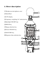
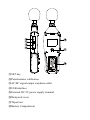
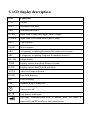
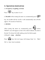
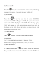
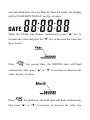
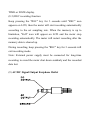
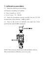
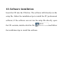
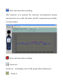
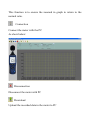
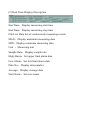
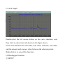
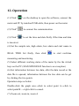
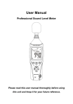
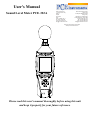
User's Manual
Sound Level Meter PCE-322A
PCE Americas Inc.
711 Commerce Way
Suite 8
Jupiter
FL-33458
USA
From outside US: +1
Tel: (561) 320-9162
Fax: (561) 320-9176
[email protected]
PCE Instruments UK Ltd.
Units 12/13
Southpoint Business Park
Ensign way
Hampshire / Southampton
United Kingdom, SO31 4RF
From outside UK: +44
Tel: (0) 2380 98703 0
Fax: (0) 2380 98703 9
[email protected]
www.pce-instruments.com/english
www.pce-instruments.com
Please read this user's manual thoroughly before using this unit
and keep it properly for your future reference.
Contents
1. Safety.......................................................................... 1
2. General description..................................................... 2
3. Specifications ............................................................. 3
4. Meter description........................................................ 5
5. LCD display description ............................................. 7
6. Operation instruction .................................................. 8
7. Calibration procedure ............................................... 14
8. Basic operation ......................................................... 15
9. Operating procedures ............................................... 16
10. Software installation ............................................... 17
11. Software interface introduction .............................. 18
12. Operation ................................................................ 24
13. Notes....................................................................... 26
14. Accessories ............................................................. 27
1.
Safety
Read the following safety information carefully before attempting
to operate or service the meter.
Use the meter only as specified in this manual; otherwise, the
protection provided by the meter may be impaired.
◆Environment conditions:
Altitude up to 2000 meters
RH≤90%(Non-Condensation)
Operating Temperature: -20~60℃
◆Maintenance
Repairs or servicing not covered in this manual should only be
performed by qualified personnel.
Wipe the unit with a dry soft cloth. Do not use abrasives or
solvents on this instrument.
◆Safety Symbol
Comply with EMC
1
2. General description
This Sound Level Meter is designed to meet the measurement
requirements of safety Engineers, Health, Industrial safety offices
and sound quality control in various environments like
construction, factories, schools, offices, traffic access, household,
stereos, etc.
◆Comply with IEC61672-1 CLASS2 standard
◆Max/Min record
◆Over range indication
◆Under range indication
◆Time, data transmission display
◆A & C Weighting
◆Selectable response time: FAST/SLOW
◆Analog AC/DC outputs for connection to frequency analyzer or
X-Y shaft recorder
◆PC real-time monitoring, recording and memory
◆4digits LCD display with a resolution of 0.1dB
◆Sampling time: 2 times/second.
3. Specifications
Applied standard
IEC61672-1 CLASS2
Accuracy
±1.4dB
Frequency range
31.5Hz~8kHz
Dynamic range
50dB
Lo:30dB~80dB
Measuring level
Med:50dB~100dB
range
Hi: 80dB~130dB
Auto:30dB~130dB
Frequency
weighting
A&C
Time weighting:
FAST 125ms;SLOW ( 1s )
Microphone
1/2 inch electret condenser microphone
Display
4digits LCD display with a
resolution of
0.1dB
Sampling time
2 times/sec
Max Hold
MAX
Min Hold
MIN
HOLD:
Hold the readings
“OVER”is when input is more than upper
Alarm function
limit of range.
“UNDER”is when input is less than lower
limit of range.
AC/DC
Analog output
outputs from earphone outlet
AC=1Vrms ,DC=10mV/dB
Meter memory:
262100
readings
PC monitors and records in real-time, each
Data recording:
Auto power off
Power supply
Battery life
Operating
conditions
Storage conditions
Dimension
(L*W*H)
Weight:
15,000 readings will be saved one time
automatically.
Meter automatically shuts down after
approx. 15 minutes inactivity.
One 9V battery, 006P or IEC 6F22 or
NEDA 1604.
at least 30 hours
-20~60℃; 10%RH~90%RH
-20℃~60℃; 10%RH~75%RH
252*66 *33 mm
262g
4. Meter description
①Windscreen microphone cover
②Metal Rod
③LCD display
④Frequency weighting A/C selection key
⑤Backlight ON/OFF key
⑥HOLD key
⑦Range selection key
⑧Power ON/OFF key
⑨MAX/MIN key
⑩Response time selection key
⑪SET key
⑫Potentiometer calibration
⑬AC/DC signal output earphone outlet
⑭USB interface
⑮External DC 9V power supply terminal
⑯Dustproof cover
⑰Tripod nut
⑱Battery Compartment
5. LCD display description
Icon
Function
LCD
4 digits
MAX
Maximum data hold
MIN
Minimum data hold
OVER
Input value is more than upper limit of range.
UNDER
Input value is less than lower limit of range.
FAST
Fast response
SLOW
Slow response
dBA
A frequency weighting(the noise that human ear can hear)
dBC
C frequency weighting (response to machine monitor)
88 ~188
Range display
TIME
Display current time(Hour-Minute-Second)
DATE
Display current date(Year-Month-Day)
AUTO
Auto level range selection
HOLD
Data hold function
REC
Data recording
Full
Memory is up to limitation
Auto power off
Low battery indication
Real-time communication icon: it flashes when the meter is
connected with PC to achieve data transmission.
6. Operation instruction
(1) Frequency weighting selection:
Press "
" key to select A or C.
(2) Backlit: After turning the meter on, momentarily press "
"
key, the backlit will be on/off, it will automatically turn off after
approx. 30 seconds of inactivity.
(3) HOLD:
After turning the meter on, momentarily press "
" button,
"HOLD" icon will appear on the LCD, which indicates the data is
freezed. To release the held reading, press the button again.
(4) Level
range
selection:
Press “
” key, the level range will change from ‘Lo’, ‘Med’,
‘Hi’ to ‘Auto’ level circularly.
(5) Power on/off:
" key for 1 second to turn on the meter, while keep
Press the"
pressing it for approx. 3 seconds, the meter will be off.
(6) MAX/MIN
Press the "
" key for one time to enter MAX/MIN
measurement, ‘MAX’ will appear on LCD, the captured maximum
sound level will be displayed on the LCD. Press the key again,
‘MIN’ will appear on LCD and minimum sound level will be
displayed on the LCD. Press the button one more time to exit
MAX/MIN measurement mode.
(7) FAST/SLOW
Press “
” to select FAST or SLOW time weighting
measurement.
FAST: Fast sampling measurement, 1 time per 125ms.
SLOW: Slow sampling measurement, 1 time per second.
(8) Date & Time Set
(8.1) Keep pressing the "
" key before power the meter on,
then power the meter on and release this key when the DATE icon
and data flash,enter into the Date & Time Set mode, the display
will be YEAR-MONTH-DAY, see fig. as below:
When the YEAR data flashes continuously, press "▲" key to
increase the value and press the "▼" key to decrease the value.See
fig.as below:
Press "
" the second time, the MONTH data will flash
continuously, then press “▲” or “▼” to increase or decrease the
value. See fig. as below:
Press "
" the third time, the DAY data will flash continuously,
then press "▲" or "▼" to increase or decrease the value. See
fig.as below:
Press "
" the fourth time, the TIME icon and HOUR data
flash, then press "▲" or "▼" to increase or decrease the value.
See fig.as below:
Press "
" the fifth time, the MINUTE data flash, then press
“▲” or “▼” to increase or decrease the value. See fig.as below:
After finish the Date & Time set, press "PEAK" key to save the
data and exit this mode.
(8.2 )TIME/DATE Display
After power the meter on, press "
" key one time to convert
TIME or DATE display.
(8.3) REC recording function
Keep pressing the "REC" key for 3 seconds until "REC" icon
appears on LCD, then the meter will start recording automatically
according to the set sampling rate. When the memory is up to
limitation, "Full" icon will appear on LCD and the meter stop
recording automatically. The meter will restart recording after the
memory data is cleared up.
During recording, keep pressing the "REC" key for 3 seconds will
exit recording mode.
Note: External power supply must be connected for long-time
recording to avoid the meter shut down suddenly and the recorded
data lost.
(9) AC/DC Signal Output Earphone Outlet
AC: Output voltage: 1Vrms corresponding to each range step.
Output impedance: 100Ω
DC: Output voltage: 10mv/dB
Output impedance:approx.1KΩ
(10) External power supply:
DC 9V input
External DC 9V, positive inside and negative outside
Pore size:OD 3.5mm, ID 1.35mm
7. Calibration procedure
(1)
Make the following switch settings:
a) Frequency weighting: A-weighting
b) Time weigh tin g: FAST
c) Level ran ge: 5 0 ~100dB
(2)
Insert the microphone housing carefully into the 1/2 inch
insertion hole of the calibrator(94dB @ 1kHZ).
(3)
Turn on the switch of calibrator and adjust the CALL
potentiometer until 94.0dB is displayed.
NOTE: This meter has already been calibrated before delivery.
The recommended recalibration cycle is one year.
8. Basic operation
(1) Open battery cover and install a 9-volt battery in the battery
compartment.
(2) Close the battery compartment.
(3) When the low battery icon "
" appears, replace the
meter's battery.
(4) when the AC adapter is used, insert the plug of the adapter
(3.5φ) into the DC 9V connector on the side panel.
9. Operating procedures
(1) Power on the meter.
(2) Press ‘
’ button to select desired level range.
(3) Select ‘dBA’ for general noise sound level and ‘dBC’ for
measuring sound level of acoustic material.
(4) Select ‘FAST’ for instant sound and ‘SLOW’ for average
sound level.
(5) Select ‘
’ button for measuring maximum and minimum
noise level.
(6) Hold the meter in hand or use the tripod to fix the meter in the
desired location. The best measuring distance is 1~1.5m away
from the microphone to the sound source.
(7) To view the current time or date, press the 'SET' key to select
the display function: TIME: current time; DATE: current date.
10. Software installation
Insert the CD into the CD-drive. The software will directly run the
setup file, follow the installation tips to install the PC professional
software; if the software can not run the setup file directly, open
the CD contents, double-click the file
the installation tips to install the software.
and follow
11. Software interface introduction
(1) Menu & Toolbar
As show below:
The icons on the toolbar from left to right are as below:
File opening
Open the saved data file, the data and curve drawing will be
displayed on the PC interface to be analyzed and evaluated.
File saving
Save the measuring data to the hard disk of a PC, saving address
and name can be defined by the user.
Time adjustment
This function is to adjust the meter's time in accordance with the
PC time, the date can be set in three kinds of common format to
facilitate the user's habit of different areas.
Start real-time data recording
This function is to monitor the real-time environmental sounds
and draw the curve after the meter and PC connected successfully.
As show below:
Stop real-time data recording
Zoom out
Zoom out
the display ratio of the graph when analyzing it.
Zoom A
This function is to ensure the zoomed in graph to return to the
normal ratio.
Connection
Connect the meter with the PC
As show below:
Disconnection
Disconnect the meter with PC
Download
Upload the recorded data in the meter to PC
(2) Real Time Display Description
Star Time:Display measuring start time
End Time:Display measuring stop time
File List: Data list of continuously measuring record
MAX:Display maximum measuring data
MIN:Display minimum measuring data
Unit :Measuring unit
Sample Rate:Display sample rate
High Alarm:Set upper limit alarm data
Low Alarm:Set low limit alarm data
Data No.:Display data number
Average:Display average data
Start Name:Set save name
(3) A-B Graph
Double-click the left mouse button on the curve interface, and
then click to select intervals shown in the figure above,
Form A-B will show the start time, start value, end time, end value,
and the amount and average value between the selected points.
Right-click is to cancel this function;
(4) Datalogger Function
①SETUP
Set data sampling rate, Date and Time format in the above shown
table. Other options can be the same as default settings.
②Down Load
This function is to upload the recorded data in the meter to PC.
③Clear Memory
This function is to clear up the recorded data in the meter.
Note: All the recorded data will be lost after clearing memory.
Please upload the data to PC before operation.
12. Operation
(1) Click "
" on the desktop to open the software, connect the
meter and PC by matched USB cable, then power on the meter.
(2) Click"
" to connect the communication.
(3) Click "
" to set the time and date firstly if the time and data
is incorrect.
(4) Set the sample rate, high alarm, low alarm and start name in
REAL TIME list firstly, then click
to start real-time
measuring and monitoring.
(5) Select different working status of the meter by the the virtual
keys on the PC (MAX/MIN/HOLD function is an exception)
(6) Get information between two data, after the data record or the
data file is opened, information between the two data can be get
by clicking the two points.
Operation steps as below:
Double-click the graph area→click to select point A→click to
select point B → right-click to cancel.
(7) Zoom out, zoom in, zoom A
As show below: Press and hold the left button to enlarge the
selection area
Click
in toolbar to zoom out the graph, click
in toolbar
to display full graph.
(8) Power off
When measurement finished, click the virtual shutdown button on
the PC to shut off the meter to save battery.
13. Notes
(1) Do not store or operate the meter in high temperature or
humidity.
(2) Remove the battery when the meter is to be stored for long
periods of time to avoid battery leakage.
(3) Wind blowing across the microphone increases the noise
measurement. Use the supplied windscreen to cover the
microphone when appliance.
(4) Keep microphone dry and avoid severe vibration.
(5) If the date and time automatically resume to default setting
after power the meter on, which indicates the battery power is low,
replace the meter's battery.
14. Accessories
◆ User's manual
◆ Windscreen
◆ Regulator rod
◆ 9V battery
◆ Φ3.5 earphone plug
◆ Software
◆ USB cable
◆ Adaptor
◆ Tripod (optional)