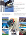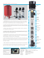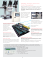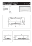
1
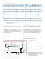
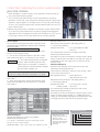
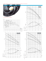
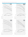
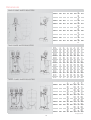
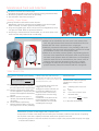
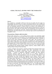
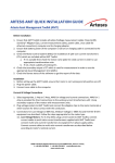
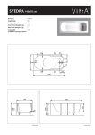
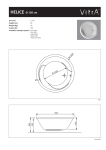
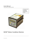
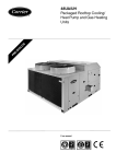
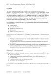
Water Boosters
ALD 400-600 Series
New Electronic Control System
TSEK
Alarko Water Boosters
Certain solution for water problem by high quality, efficient
water boosters. In order to pressurize the drinking, usage,
process and irrigating waters continuously in safe and
economical conditions…
ALD 400-600 Series
QUALITY PRODUCT
NEW SERIES intelligent electronical control box ensuring
ease of usage and servicing, balancing the operation.
Reliable capacities. Quiet and non-stop water comfort.
Low operational cost, low current consumption.
Valve included. Ready to use.
Protected for usage without water.
Packaged system.
Easy mounting.
No maintenance, no problem.
QUALITY SERVICE
Alarko water boosters are throughout the world with service
warranty of Alarko Carrier which is the leading company in
water boosters and water pressurizing area. Right product
selection and right mounting by qualified and authorized
distributors. 2 years warranty. Original spare parts.
Maximum 123 m3/h flow rate, wide model
and capacity range for various conditions
up to 10 bar pressure. 21 models of single pump,
21 models of two pumps, 21 models
of three pumps, in total 63 models.
Villas, apartments and
group of buildings
District,village, small town
and towns
Hospitals, schools and
commercial buildings
Gardens and parks
Hotels, social facilities
and holiday villages
Depot, refinery, dockyard, factory,
water treating and industrial facilities
2
Farms and greenhouses
Reliable High Technology
Motor
1
3
Coupling
2
4
Pump Head
(Outlet)
5
6
7
8
Outher
Sleeve
Rubber
Gasket
1. MEMBRANED TANK: Stores pressurized water, decreases starts and stops of
pumps. Prevents the fittings from shocks and vibrations. Hygenic and scentless.
Not included in standard water booster set, sold separately. (Page 11)
2. OUTLET COLLECTOR: Galvanized. The check valve on the output of the pump
prevents the pressurized water from going back to the pump. There are manometer
and pressure switches on it.
3. MOTOR: Special design for vertical operating conditions. 380 V, 3 phases, 50
Hz. Protected from excess currents.
4. CONTROL PANEL: Intelligent Electronical Control Management System for multi
pump Alarko water boosters. (Page 4). Thermal protected contactor for single
pump water boosters and ON/OFF switch.
5. FLEXIBLE HOSE: Provides the water connection between the pump group and
membraned tank. Stainless steel. Mounting is very easy, no proficiency required.
Obtains flexibility in placing the tank. Sold separately.
Shaft Seal
Interval
Pump Shaft
Difusor
(Complete)
Steep Ring
Impeller
Diffuser
Cover
6. INLET COLLECTOR: Galvanized. There are spherical valves on the inputs of each
pump in two and three pump water boosters. So, in case one of the motopumps
break down, the other continues to supply water and the broken one can be
removed to be fixed.
Interval
7. BASE: Galvaniized. Can be easily fixed on the ground. Prevents noise and vibration.
Pump Head
(Inlet)
Rubber Gasket
Bearing
8. FLOAT SWITCH: Prevents the water booster from operating in case the reservoir
goes out of water. When it is full, the water booster starts automatically.
PRESSURE SWITCH:
On the outlet line. Start
and stop the pumps to
obtain the pressure in the
plumbing.
The number of switches
are as much as the
number of the pumps. They are adjusted in the factory
as to operate the pumps at the most efficient point.
PUMP MATERIAL:
High quality, suitable for various operating conditions.
Pump Heads
GG20
Outher Sleeve Stainless, X2CrNi1911/X2CrNiMo17122
Pump Shaft
Stainless, X46Cr13
Diffusor
%30 Glass reinforced PPO
Impeller
%30 Glass reinforced PPO
Shaft Seal
Ceramic,Carbon
Coupling
Bronze
3
New Age Intelligent Electronical
Control Management
Electronical Microprocessor control management system, brings
a safe and economical usage by controlling the operational
functions of the two and three pumps water boosters. The control
management system, collected in compact inner and outer
designed box, is delivered mounted on the water boosters and
connected.
The LCD display is mounted
on the cover of the control
box to be seen easily. It is
easy to use and every
operation can be followed
up from that display.
Operator Panel Protection:
2A glass fuse before 24 VAC input.
3,2 V Ni-Cd Battery. Protects the
data in case of a power failure.
Protection for Waterless Operation:
The water level in the reservoir
continuously by level
electrodes and water
relay.Electronical
management system
prevents the pumps from
operating if water is not in the
required level.
is checked
Microprocessor board.
level
Screen Board.
False Pressure Signal Protection:
Electronical Management System
prevents the pumps from operating
in case of sudden changes in water
pressure.
Motor Phase Protection:
Excess Current Control:
Electronical Management System
prevents the motor from loosing one
phase and operate with remaining two
phases. If one of the phases is lost then
motor is stopped.
Electronical Management System
protects the motor from breaking
down in case of excess current is
consumed by cutting the power.
Phase Order Control:
Electronical Management System controls each of
the motors to see if the phase connections are in
the correct order. It prevents the pumps to turn in
the wrong direction.
Sequential Automatic Operation:
Electronical Management System manages the pumps to operate
sequentially in order to keep the adjusted facility pressure and stop
when the usage decreases.
● The first operating pump changes in every usage automatically.
● So, the usage times of motor and pumps are equalized.
1.LCD Display: The informations like operation mode (manual/automatic) of the water booster, total operation
time of each pump, operating or stopped pumps, (if present) malfunction type (wrong direction, phase protection,
excess current, waterless operation) can be reached by this display.
2. Manual mode/esc button and LED
3. Automatic mode button and LED
1
4. Changing the parameters
5. Parameter changing mode and scroll between parameters
2
4
7
6. Manual operation of the pumps
6
8
3
5
7. “Pump in operation” LED
8. “Pump malfunction” warning LED
The panels vary according to the
number of pumps.
4
Water boosters which are manufactured
thinking of you, together with you...
Alarko, leading the research and development studies of underwater pumps,circulation pumps and water pressurizing systems
of future technology in 60s and 70s, became the developer of the domestic products in the water booster sector.
In Turkey, there is a past between Alarko
and the water booster users of 40 years.
There is a relation, which has been tested,
sincere, full of intimacy, lifetime lasting,
improving and widening. Alarko has never
left anyone on halfway.
Alarko, thought the best for everyone who
had selected it. Always aimed to meet
their requirements. Alarko was happy
when they are happy. Gained much more
than what it has invested. The words
“much more than” don’t mean material.
It is the confidence of 40 years.
The “magic” formula behind this success
is “Quality in Manufacturing and Service”
Continuously innovating
mentality...
Alarko water boosters are result of 40 years’ experience.
Alarko water boosters are being continuously improved by taking
notice of varying needs and technologies.
They are manufactured conforming with the quality conditions in
ISO 9001 certified facilities and watertightness and performance
tests are applied to each of the water boosters.
Everthing is “first class”
Alarko Carrier presents “first class”
engineering and free information
to the customers with world wide
experienced seller network.
All information, prices and
selection tool can be reached by
internet from the address
www.alarko-carrier.com.tr
5
Technical Specifications
Water
Motor
Power Inlet/Outlet
(inches)*
(HP)
TYPE
403/10-1
403/15-1
403/16-1
406/11-1
406/15-1
406/18-1
408/10-1
408/14-1
408/17-1
610/8-1
610/10-1
610/12-1
615/7-1
615/9-1
615/10-1
620/7-1
620/8-1
620/9-1
631/6-1
631/7-1
631/8-1
1
1,5
2
2
3
4
3
4
5,5
4
5,5
7,5
5,5
7,5
10
7,5
10
10
15
15
15
Tank
Weight
Connection
(inches)**
(kg)
1"-1"
1"-1"
1"-1"
1"-1"
1"-1"
1"-1"
1 1/2"-1 1/2"
1 1/2"-1 1/2"
1 1/2"-1 1/2"
1 1/2"-1 1/2"
1 1/2"-1 1/2"
1 1/2"-1 1/2"
1 1/2"-1 1/2"
1 1/2"-1 1/2"
1 1/2"-1 1/2"
2"-2"
2"-2"
2"-2"
2"-2"
2"-2"
2"-2"
TYPE
Water
Inlet/Outlet
(inches)*
1
1,5
2
2
3
4
3
4
5,5
4
5,5
7,5
5,5
7,5
10
7,5
10
10
15
15
15
2"-1 1/2"
2"-1 1/2"
2"-1 1/2"
2"-1 1/2"
2"-1 1/2"
2"-1 1/2"
2 1/2"-2"
2 1/2"-2"
2 1/2"-2"
3"-2 1/2"
3"-2 1/2"
3"-2 1/2"
3"-2 1/2"
3"-2 1/2"
3"-2 1/2"
4"-3"
4"-3"
4"-3"
4"-3"
4"-3"
4"-3"
403/10-2
403/15-2
403/16-2
406/11-2
406/15-2
406/18-2
408/10-2
408/14-2
408/17-2
610/8-2
610/10-2
610/12-2
615/7-2
615/9-2
615/10-2
620/7-2
620/8-2
620/9-2
631/6-2
631/7-2
631/8-2
37
40
44
42
50
57
40
50
65
96
107
115
105
113
120
111
118
119
139
140
141
1"
1"
1"
1"
1"
1 1/2”
1 1/2”
1 1/2”
1 1/2”
1 1/2”
1 1/2”
1 1/2”
1 1/2”
1 1/2”
1 1/2”
2"
2”
2”
2”
2”
2”
Motor
Power
(HP)
Tank
Weight
Connection
(inches)**
(kg)
1"
1"
1"
1"
1"
1 1/2”
1 1/2”
1 1/2”
1 1/2”
1 1/2”
1 1/2”
1 1/2”
1 1/2”
1 1/2”
1 1/2”
2"
2”
2”
2”
2”
2”
87
92
97
102
110
81
70
79
100
135
157
171
155
169
182
175
183
185
225
227
229
TYPE
403/10-3
403/15-3
403/16-3
406/11-3
406/15-3
406/18-3
408/10-3
408/14-3
408/17-3
610/8-3
610/10-3
610/12-3
615/7-3
615/9-3
615/10-3
620/7-3
620/8-3
620/9-3
631/6-3
631/7-3
631/8-3
Motor
Power
(HP)
1
1,5
2
2
3
4
3
4
5,5
4
5,5
7,5
5,5
7,5
10
7,5
10
10
15
15
15
Water
Tank
Weight
Inlet/Outlet Connection
(inches)*
(inches)**
(kg)
2 1/2"-2"
2 1/2"-2"
2 1/2"-2"
2 1/2"-2"
2 1/2"-2"
2 1/2"-2"
3"-2 1/2"
3"-2 1/2"
3"-2 1/2"
4"-3
4"-3
4"-3
4"-3
4"-3
4"-3
5"-4"
5"-4"
5"-4"
5"-4"
5"-4"
5"-4"
1"
1"
1"
1"
1"
1 1/2”
1 1/2”
1 1/2”
1 1/2”
1 1/2”
1 1/2”
1 1/2”
1 1/2”
1 1/2”
1 1/2”
2"
2”
2”
2”
2”
2”
102
127
113
162
170
105
100
108
135
174
207
227
205
225
244
239
248
251
311
314
317
Notes: Pipe diameters are for galvanized pipes. The inner diameters of plastic pipes are narrower than galvanized pipes. In case plastic pipes will be used,
it should meet the inner diameter of galvanized pipe.
(*) Water inlet and outlet diameters are equal on the pump. But suction fittings should be wider than it. For example, if inlet is 2” then the suction
fittings should be 2,5”,etc.
CORRECT USAGE
●
●
●
●
●
●
●
●
●
●
The suction should not be from a lower height for the water
boosters.
The water booster should not be directly attached to the
city network.
It should not be difficult for the pumps to absorb the water.
So, water booster suction diameters should not be made
smaller. The pump should be one degree wider than the
water inlet diameter for single pump water boosters, the
suction fittings should be as the suction collector for two
or three pumps water boosters.
The inner diameters of plastic pipes are narrower than
galvanized pipes. In case plastic pipes will be used, it should
meet the inner diameter of galvanized pipe.
The base should be fixed on the ground (on rubber battens
if possible) in order not to make noise.
ASSEMBLY WATER BOOSTER DIAGRAM
Outlet To
Building
Valve Check Valve Valve
City Water
Inlet
STANDARD DELIVERY
CONTENTS
●
Valve
Tap With Float
Stopper
●
Check Valve
Overflow
Tap
Max. Level
Valve
Reservoir
Min. Level
30 cm
WATER BOOSTER
●
CORRECT INSTALLATION
Water booster should never be operated without water.
The air inside the pump should be removed before
operating.
The level indicators and electrods, which are given with
the water boosters, should be placed in the reservoir.
The air pressure of the membrane tank should be 0,5 bar
lower than the operating pressure. The air pressure should
be checked periodically.
While compressing air in the membraned tank or measuring
the pressure, the tank should be empty.
Water temperature should be between 0-35°C and
environment temperature should be maximum 40°C.
The water should not be allowed to freeze in the water
booster.
~40 cm
●
●
●
SUPPLIED MATERIALS
●
10 cm
Filter For Dirt
●
Valve
Float Switch
Ready to use compact electronical
connection box.
Suction collector on which valves are
mounted to the outlet of each pump, and
manometer.
Float switch for controlling the water level.
User manual and authorized services list.
Drainage
●
6
Membraned tank (certainly should be used)
Steel weaved flexible hose for membraned
tank-motopump connection.
Membraned tank air manometer.
Critical Point: Selecting the correct water booster
SELECTION CIRITERIA
●
●
●
When deciding for a water booster, its the operation range should be on
top of the pump efficiency graphic.
Two or three pumps water booster can be used instead of one pump
hydrophor. In this case, noise and pressure effects because of a big pump’s
operation, will not appear. For example, three 5 m3/h pump water booster
or two 7,5 m3/h pump water booster could be used instead of one 15 m3/h
pump water booster.
Multi pump water booster, if suitable, can be used as a spare water booster.
So, in case one pump breaks down, the other pump(s) should supply the
required flow rate. For example, if the flow rate should be 10 m3/h, two 10
m3/h pump or three 5 m3/h pump water booster could be selected.
How to Select
The required pressure (Hm) and flow rate (Q) values
should be known for selecting a water booster. Calculating
Hm and Q values:
Required Pressure=Hmin(mSS)=h+h+15
h – The height in meters between the water booster
location and the highest storey.
h – It is the loss in pressure because of the valve, meter
and calcificated pipes. h is assumed as 0,2 times h.
∆h = 0.2h
Number of flats = 21
Daily Personal Consumption= 100 lt/day (Table 1)
F – Factor=0,35 (Table 2)
Required Flow Rate
= Q = 21x5x100x0,35/1000
= 3,6 m3/h
(It is assumed that 5 persons are living in each flat)
Selecting the Water Booster:
According to the above calculation, pressure range is 40-60
meters or 40-70 meters and 403/10-1 or 403/15-1 types can
be selected for they can supply 3,5 m3/h flow rate in this
pressure range.
Selection Example 2:
Water boosters selection for 9 storeys 30 rooms hotel.
Calculating the required pressure:
h=(9 storeys+1 basement) x 2,8m (h of one storey) = 28 m
h=0,2 x h=0,2 x28 m=5,6 m
Min required pressure
= Hmin=28+5,6+15
= 48,6 mSS=50 mSS=5 bar
Daily Personal Consumption= 150 lt/day (Table 1)
F – Factor=0,3 (Table 2)
Required Flow Rate
= Q = 270 rooms x 2 beds
x150x0,3/1000 = 24,3 m3/h
(It is assumed that 2 beds are present in each room)
Selecting the Water Boosters:
According to the above calculation, pressure range is 50-70
meters or 50-80 meters and 631/7-1 or 408/14-3 (50-70
range), 610/10-2 (50-80 range) types can be selected for they
can supply 24,3 m3/h flow rate in this pressure range.
15 – The value estimated from the required
pressure, which should be present in the
highest storey. For example, 15 meters for
1,5 bar pressure. If required pressure changes
then that value changes, too.
Required Flow Rate=Q(m3/h)=#of flats x #of persons
in the flat x Daily Personal Consumption x F/1000
Daily Personal Consumption (lt/day) value is selected
from Table 1.
F – Same time usage factor shows the maximum water
usage of the inhabitants at the same time. It is selected
from Table 2.
Table 1: Daily Personal
Consumption
Settlement
Type
Hand-basin
House Shower
Basin
Shower
Hotel
Basin
Hospital
School
Pre-school
Créche
Barracks
Restaurant
Gardening
Car wash
Daily Personal
Consum
(lt/per.)
60-80
80-115
120-200
100
150-200
200-500
5
80-100
100-150
60-80
10-20
1,5 lt/m2 each
100 lt/day
Table 2: Same Time
Usage Factor
Settlement Type
Houses
Hotels
Hospitals
1-5 st.
6-10 st.
11-20 st.
21-50 st.
51-100 st.
100 + sto
1-20 beds
21-50 beds
50 + beds
50-500 beds
501-1000 beds
1001-2000 beds
Schools
Pre-school
Barracks
Commercial Building
Faktör
0,66
0,45
0,40
0,35
0,30
0,25
0,40
0,40-0,30
0,30-0,20
0,30-0,20
0,20-0,15
0,15-0,10
0,30
0,40
0,40-0,30
0,30
EASY AND QUICK
SOLUTION FROM WEB
Selection Example 1:
Hydrophors can be
quickly selected from the
selection tool in
www.alarko-carrier.com.tr
The prices can be learned
and price offer can be
prepared.
Water booster selection for 7 storeys 21 flats building.
Calculating the required pressure:
h = (7 storeys + 1 basement) x 2,8 m (h of one storey) = 22,4 m
∆h = 0,2 x h = 0,2 x 22,4 m = 4,48 m.
Gerekli Min. Bas›nç = Hmin = 22,4 + 4,48 +15 = 41,88 mSS= 4,1 bar.
7
ORDER NOTATION
ALD 6 10 / 8 - 3
Number of Pumps
Steps
Nominal Flow Rate (m3/h)
Pump Case Diameter (inches)
Type
ALD 400 Series Pump Performance Curves
100
90
16
80
15
403
70
H (m)
60
10
50
40
30
20
General Charts
10
0
80
12
η
60
NPSH (m)
η (%)
8
40
4
NPSH
SINGLE PUMP
TWO PUMPS
TWO PUMPS
THREE PUMPS
100
THREE PUMPS
3
4
5
6
2
4
6
8
10
12
3
6
9
12
15
18
17
18
14
80
15
70
60
H (m)
60
11
10
50
40
40
30
30
20
20
10
10
0
0
70
8
45
NPSH (m)
4
η (%)
65
η
NPSH
0
SINGLE PUMP
25
3
4
5
6
7
8
9
TWO PUMPS
6
8
10
12
14
16
18
THREE PUMPS
9
12
15
18
21
24
27
6
60
4
50
2
40
NPSH
0
30
SINGLE PUMP
Q (m3/h)
NPSH (m)
8
η
η (%)
50
5
7
9
11
13
10
14
18
22
26
15
21
27
33
39
TWO PUMPS
THREE PUMPS
8
Q (m3/h)
70
408
90
80
H (m)
2
100
406
90
1
Q (m3/h)
20
0
SINGLE PUMP
ALD 600 Series Pump Performance Curves
110
100
12
100
10
610
615
90
9
90
10
80
8
70
H (m)
H (m)
80
70
7
60
60
50
50
40
40
30
30
η
6
6
70
70
NPSH
2
7
9
11
13
10
14
18
22
26
15
21
27
33
39
TWO PUMPS
THREE PUMPS
THREE PUMPS
8
10
12
14
16
18
20
16
20
24
28
32
36
40
24
30
36
42
48
54
60
90
9
620
7
8
70
80
6
60
60
50
50
40
40
30
30
20
η
60
NPSH (m)
4
NPSH
2
65
5
55
NPSH
45
3
50
SINGLE PUMP
14
16
18
20
22
24
26
TWO PUMPS
24
28
32
36
40
44
48
52
Q (m3/h)
SINGLE PUMP
12
THREE PUMPS
η
7
70
η (%)
NPSH (m)
6
15
19
23
27
31
35
39
43
30
38
46
54
62
70
78
86
45
57
69
81
93
105
117
129
TWO PUMPS
THREE PUMPS
36
42
48
54
60
66
72
78
9
η (%)
7
H (m)
H (m)
631
8
80
90
70
ηη (%)
50
Q (m3/h)
100
NPSH
SINGLE PUMP
Q (m3/h)
5
60
2
50
SINGLE PUMP
TWO PUMPS
4
Q (m3/h)
60
NPSH (m)
4
η (%)
NPSH (m)
η
Dimensions
SINGLE PUMP WATER BOOSTERS
TYPE
403/10-1
403/15-1
403/16-1
406/11-1
406/15-1
406/18-1
408/10-1
408/14-1
408/17-1
610/8-1
610/10-1
610/12-1
615/7-1
615/9-1
615/10-1
620/7-1
620/8-1
620/9-1
631/6-1
631/7-1
631/8-1
A
434
434
434
434
434
434
434
434
434
514
514
514
514
514
514
516
516
516
516
516
516
B
477
477
487
487
487
496
512
521
533
553
565
585
565
585
678
592
687
687
687
687
687
C
278
278
278
278
278
278
278
278
278
308
308
308
308
308
308
308
308
308
308
308
308
D
200
200
200
200
200
200
200
200
200
250
250
250
250
250
250
250
250
250
250
250
250
H
939
1089
1136
1129
1326
1485
1131
1341
1495
1105
1214
1355
1128
1273
1320
1227
1280
1333
1281
1343
1405
H1
578
728
758
751
923
1052
728
908
1043
629
719
809
633
727
774
681
734
787
697
759
821
H2
121
121
121
121
121
121
121
121
121
125.5
125.5
125.5
125.5
125.5
125.5
125.5
125.5
125.5
125.5
125.5
125.5
TYPE
403/10-2
403/15-2
403/16-2
406/11-2
406/15-2
406/18-2
408/10-2
408/14-2
408/17-2
610/8-2
610/10-2
610/12-2
615/7-2
615/9-2
615/10-2
620/7-2
620/8-2
620/9-2
631/6-2
631/7-2
631/8-2
A
616
616
616
616
616
616
617
617
617
717
717
717
717
717
717
719
719
719
719
719
719
B
633
633
633
633
633
633
669
669
669
738
738
738
738
738
738
761
761
761
761
761
761
C
378
378
378
378
378
378
378
378
378
408
408
408
408
408
408
408
408
408
408
408
408
D
502
502
502
502
502
502
502
502
502
650
650
650
650
650
650
650
650
650
650
650
650
H
939
1089
1136
1129
1326
1485
1131
1341
1495
1105
1214
1355
1128
1273
1320
1227
1280
1333
1281
1343
1405
H1
578
728
758
751
923
1052
728
908
1043
629
719
809
633
727
774
681
734
787
697
759
821
H2
121
121
121
121
121
121
121
121
121
125,5
125,5
125,5
125,5
125,5
125,5
125,5
125,5
125,5
125,5
125,5
125,5
TYPE
403/10-3
403/15-3
403/16-3
406/11-3
406/15-3
406/18-3
408/10-3
408/14-3
408/17-3
610/8-3
610/10-3
610/12-3
615/7-3
615/9-3
615/10-3
620/7-3
620/8-3
620/9-3
631/6-3
631/7-3
631/8-3
A
917
917
917
917
917
917
917
917
917
1119
1119
1119
1119
1119
1119
1119
1119
1119
1119
1119
1119
B
650
650
650
650
650
650
683
683
683
768
768
768
768
768
750
803
785
785
785
785
785
C
378
378
378
378
378
378
378
378
378
408
408
408
408
408
408
408
408
408
408
408
408
D
830
830
830
830
830
830
830
830
830
1050
1050
1050
1050
1050
1050
1050
1050
1050
1050
1050
1050
TWO PUMPS WATER BOOSTERS
THREE PUMPS WATER BOOSTERS
10
H1
H2
H
578
121
939
728
121
1089
758
121
1136
751
121
1129
923
121
1326
1052 121
1485
728
121
1131
908
121
1341
1043 121
1495
629 125,5
1105
719 125,5
1214
809 125,5
1355
633 125,5
1128
727 125,5
1273
774 125,5
1320
681 125,5
1227
734 125,5
1280
787 125,5
1333
697 125,5
1281
759 125,5
1343
821 125,5
1405
Tüm ölçüler mm'dir.
Membraned Tank and Selection
It should be used with the water booster.
● Decreases the operation cycle of the pumps by storing pressurized water.
● Absorbs the pressure shocks from the plumbing.
● Not included in the water booster set.
Healthy, Clean Water
Certainly should be used with the water booster.
● Membranes, which are manufactured of EPDM, one of the strongest
elastic materials, are used in pressure balancing tanks.
● They are of hygienic type, which can be used in food applications. Does
not give off a smell. Does not produce bacterium.
● Air porosity is 4 times less than natural rubber. So, air cannot enter in the
water and the tank pressure does not fall eas‹ly.
Membrane Operation Principle
●
●
●
Hava
●
Water
●
Water is in the membrane, does not touch to the surface of the
tank. The gap between metal surface and membrane is full of air.
Water inlet and outlet is performed from a single pipe.
While the pressurized water enters to the plumbing, it fills in the
membrane in the same time and compresses it until the air outside
the membrane comes to the same pressure value.
When the air and water pressure equalize, the plumbing pressure
has come to the required level and pressure switch stops the pump.
The water under pressure meets the small amount of consumptions,
when the water level in the tank decreases, the volume of the air
increases and its pressure decreases. Pump starts to operate.
The bigger the tank, the less the energy consumption. Motor,
pressure switches, valves and contactors will have a longer life.
TANK SELECTION
Tank volume is calculated by the following
formula:
Vtank = 0,33 x Qmax x
(Pmax +1)
∆P x a
Qmax Maximum flow rate which can be supplied
by the pump to the system or the peak
flow rate required for the usage point (lt/h)
Pmax Maximum pressure in the system. (bar).
For home applications, the pressure should
be at least 2-3 bar higher than the minimum
pressure.
Pmin Minimum pressure in the system. If
unknown, then should be calculated by
the formula.
∆P Pressure difference (Pmax-Pmin)
a
Maximum allowed number of start-stops
for a pump motor in an hour. (number/h)
●
●
●
●
In Ministry of Public Works “1999 Unit Price and
Selection Example:
Definitions Book”, this number is max. 180 for an hour
for the motors up to 1,1 kW. also it max. 40 for an hour
for the motors more than 1,1 kW.
V tank is minimum volume of the tank.
A bigger tank can be used.
The bigger the volume of the tenk, the
less the pressure differences in the
water, less noises in water booster,
longer life for the motor less energy
consumption.
A smaller tank can be selected in the
industrial applicetions in which the
water consumption rate is standard
considering the social usage.
Membraned tank volume and pressure
calculation for 7 storeys, 21 flats
building.
Qmax = 3.600 lt/h (Water booster select
Ex.1)
Pmax
∆P
a
= 6 bars
= 2 or 3 bars. Assume as 2 bars
= 40 olarak alal›m.
Vtank = 0,33 x 3.600 x
(6+1)
= 103,9 lt.
(2x40)
So, a 100 lt tank can be selected.
Manometer is present on tanks bigger than or equal to 100 lt.
The pressure of water in the fittings can be traced by the manometer, while the water booster is operating.
If the water in the tank is emptied, manometer shows the air pressure in the tank.
The operating pressure of the tank should be more than or equal to the pressure which the pump can supply
in closed valve condition.
11
Alarko water boosters are manufactured in this facility...
ALARKO CARRIER GEBZE FACILITY-ACGK
ACGK, has a closed area of 36.800m2 on 60.500 m2 property
in Gebze Organized Industrial Zone. The construction has
begun in ist July 1999 and finished in ist November 2000. Air
conditions, fan coils, radiators, burners, cooling group, cooling
tower, circulation pumps, water boosters are manufactured in
Main Manufacturing Facility which is certified by ISO 9001.
Panel radiators are manufactured in Radiator Manufacturing
Facility, which has 1.800 m2 open, 9.250 m2 closed area in
Dudullu Organized Industrial Zone. The number of employees
in Alarko Carrier manufacturing facilities is 650, 324
employees in management, sales and marketing departments,
22 employees in research and marketing department and in
total 996 employees.
ALARKO CARRIER
SANAY‹ VE T‹CARET A.fi.
ALARKO CARRIER SANAY‹ VE T‹CARET A.fi.
GOSB-Gebze Organize Sanayi Bölgesi
fiahabettin Bilgisu Cad. 41480 Gebze/Kocaeli/TÜRK‹YE
Phone : (90)(262) 648 60 00 PBX
Telefax : (90)(262) 648 61 01
web
: www.alarko-carrier.com.tr
e-posta : [email protected]
B.3.2-6 ‹ 01 06 USTA
The company reserves its right to alter its products due to technological developments.