1
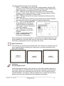
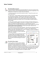
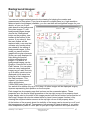
OrthoGraph User’s Manual OrthoGraph – User’s Manual © OrthoGraph Kft. 2015 All rights reserved Introduction OrthoGraph is a building survey system developed for the iPad platform. OrthoGraph is the only CAD application for the iPad that lets users sketch and create a survey for the production of detailed floor plans with instant graphic feedback on the fly. The unique approach of OrthoGraph is first to build up a hierarchical structure of building elements (buildings, stories, rooms and room parts, and different kind of room groupings), then later each building element can be drawn, similar to using a pen and paper. The exact representation of the building will be created once the correctly measured date is applied. This way creating a floor plan takes only a few minutes, and the result is a complete building survey, including an accurate plan, calculated areas, perimeter and detailed reports on the rooms. Via e-mail or through the Dropbox integration you can upload your ground plan easily to your computer, where you can use it for post processing. This document is intended to show the main features and functions of the software thus helping you taking the first steps. To start using OrthoGraph Architect as fast as possible we have created a chapter named “OrthoGraph Step by Step” that drives you through the main concept and features of the software. Another important chapter is the detailed function list of the OrthoGraph Architect module that you find in the “OrthoGraph Function List” chapter. For more help check our forum (http://forum.orthograph.net/), our website (http://www.orthograph.net/), videos on youtube (http://www.youtube.com/user/akorbuly) or contact us via mail ([email protected]). (cloud.orthograph.net) OrthoGraph – User’s Manual © OrthoGraph Kft. 2015 All rights reserved 2 Contents Introduction .......................................................................................................................... 2 Contents ........................................................................................................................... 3 OrthoGraph Step by Step .................................................................................................... 6 Introduction ...................................................................................................................... 6 OrthoGraph Workflow....................................................................................................... 6 Project: ............................................................................................................................. 7 Locations: ......................................................................................................................... 8 Sketch .............................................................................................................................. 9 Wall openings ................................................................................................................. 11 Measurements ............................................................................................................... 11 Adding more rooms: ....................................................................................................... 12 Move and pair: ............................................................................................................... 13 Match openings .............................................................................................................. 13 Match Walls .................................................................................................................... 13 Background image ......................................................................................................... 14 OrthoGraph Function list .................................................................................................... 15 Drawing tools: .................................................................................................................... 16 Pencil: ............................................................................................................................ 16 Close Polygon: ............................................................................................................... 16 Move Corner: ................................................................................................................. 16 Add Corner: .................................................................................................................... 17 Delete Corner: ................................................................................................................ 17 Bend Wall Segment:....................................................................................................... 17 Straighten a Segment:.................................................................................................... 18 Add Niche:...................................................................................................................... 18 Add Hotspot: .................................................................................................................. 18 Delete Hotspot: .............................................................................................................. 18 Elements toolbar: ............................................................................................................... 19 Place Window: ............................................................................................................... 19 Delete Window: .............................................................................................................. 19 Place One Wing Door:.................................................................................................... 19 Place Two Winged Door: ................................................................................................ 20 Delete Door: ................................................................................................................... 20 Place Object: .................................................................................................................. 21 Delete Object: ................................................................................................................ 21 Survey tools: ...................................................................................................................... 21 OrthoGraph – User’s Manual © OrthoGraph Kft. 2015 All rights reserved 3 Move Room: ................................................................................................................... 21 Match openings: ............................................................................................................. 21 Pair Walls: ...................................................................................................................... 22 Upload to Dropbox: ........................................................................................................ 22 Send by email: ............................................................................................................... 23 Delete measures: ........................................................................................................... 24 Add laser measurement device: ..................................................................................... 24 View Toolbar: ..................................................................................................................... 25 Show/Hide Measurements: ............................................................................................ 25 Show/Hide Room labels: ................................................................................................ 25 Show/Hide Room dimensions: ....................................................................................... 26 Show/Hide Reference line: ............................................................................................. 26 Show/hide grid: .............................................................................................................. 26 Show/Hide Floor covering: ............................................................................................. 26 Show/Hide labels: .......................................................................................................... 26 Show/Hide Annotation: ................................................................................................... 26 Show/Hide Objects: ........................................................................................................ 26 Background images: .......................................................................................................... 27 Add background: ............................................................................................................ 28 Delete background: ........................................................................................................ 28 Move background: .......................................................................................................... 28 Show/Hide background image: ...................................................................................... 28 Add laser measurement device: ..................................................................................... 28 Hotspot:.......................................................................................................................... 28 Display Background Image Properties: .......................................................................... 29 Common part of the main toolbar - the 2nd row: ................................................................ 29 Undo:.............................................................................................................................. 29 Redo:.............................................................................................................................. 29 Fit in Window: ................................................................................................................. 29 Pan tool: ......................................................................................................................... 29 Properties tool: ............................................................................................................... 30 Measure distance tool: ................................................................................................... 30 3D Mode: Joystick mode: .............................................................................................. 31 Settings of OrthoGraph ...................................................................................................... 33 Set the language of OrthoGraph .................................................................................... 33 Used language ............................................................................................................... 33 Used unit. ....................................................................................................................... 33 OrthoGraph – User’s Manual © OrthoGraph Kft. 2015 All rights reserved 4 Skin ................................................................................................................................ 33 Measure during ketch. .................................................................................................... 33 Disable Questioner. ........................................................................................................ 33 3D Model View ............................................................................................................... 33 Startup............................................................................................................................ 34 Show/hide locations recursively. .................................................................................... 34 Linked to Dropbox .......................................................................................................... 34 Delete database on startup ............................................................................................ 34 OrthoGraph – User’s Manual © OrthoGraph Kft. 2015 All rights reserved 5 OrthoGraph Step by Step Introduction Having a floor-plan is necessary in many cases starting from renovation / reconstruction through interior decoration to flooring or real estate utilization. The precision of this kind of document can vary depending on the field your profession, in most cases however, you don’t have any kind of documentation, and if there is any, they can be outdated and unreliable. Here at OrthoGraph we have faced with the same problems many times, and have seen that there are no existing solutions for on-site surveying running on mobile devices. What we found were such solutions that are not focusing on building survey rather on trying to be a CAD software on handhelds. They were slow, difficult, or really hard to use. This is why we have decided to create a tool for you: a tool for on-site sketch and measurement of real-estate data, including the building floor-plan, properties and objects. Please remember: OrthoGraph is not a CAD software, it is for survey, and it was designed for mobility. OrthoGraph Workflow When designing the software, we had to take into consideration the demands of a very wide user base. However, different professions have different practices, rules and customs, and it was inevitable that the work with OrthoGraph would follow a workflow, which might be different from what the users are accustomed to. This means that, while the user might already have his or her own method, a slightly different procedure is to be learnt, in order to master the program, and to get the results needed. Below, you can see how OrthoGraph should be used during an onsite work. 1. enter the location to be surveyed 2. create a location structure, if needed 3. observe the location, then you have an impression about how the location looks like (number of walls, corners, room orientation etc.) 4. make a preliminary sketch of the location outlay – no need for accuracy, the sketch will be modified later. 5. elaborate the sketch and make it more detailed with housing, bending segments, moving corners 6. make one base measurement, which will scale the drawing 7. make additional measurements by measuring the walls and the diagonals if necessary, in order to update the corner angles 8. add wall openings and set their properties 9. measure the openings 10. place objects and set their properties 11. measure the objects 12. make photos about anything important, make hand free annotations and comments 13. check your work in the 3D mode to see if it reflects the actual location 14. move to the next location, and survey it following the same procedure. 15. export your work OrthoGraph – User’s Manual © OrthoGraph Kft. 2015 All rights reserved 6 In addition, there are several basic principles the user needs to be aware of. Keeping these “golden rules” will ensure that you always get the desirable results. 1. OrthoGraph works with a location structure. Take your time to build up this hierarchy of locations and sub-locations, as this will portray the surveyed building accurately. 2. The program is able to work with different reference line settings. Even before starting sketching, make sure the reference line, where the measurements are made is positioned the way you want. 3. Keep an eye on the measurement direction. This feature lets you to control how your sketch changes. It is always the ending point of the measurement, which is pulled closer, or pushed away. 4. Finish the location, before you move to the next one. If you go back to a previously sketched room and make fundamental changes, it might distort the end result. Finish surveying the location, before you leave it. Anytime you decide to transfer the measured floor-plan to your desktop or to the office for your colleagues, you can simply upload it to your Dropbox account, or send it via mail. If you required calculations from the real measured data (e.g. wall area for painting, floor area for cleaning), just use the embedded report functionality that can make calculation for particular rooms or even for a group of rooms. Project: The first step is to create a project. The first time you open OrthoGraph, you will see one project called “New project 1”. You can access the project list on the top right corner on the top status bar. After pressing the project button the project list will appear, where you can modify the name of the project, by tapping on the Edit button, on the top right of the project window. You can create a new project by pressing the + sign left to the Edit button. You can also delete any project, but you can only leave this project window if you have at least one project open. To Delete a project simply swipe left on the project name and three icons will appear. Tap on the last icon (trash bucket), and tap on yes when the pop up window appears. OrthoGraph – User’s Manual © OrthoGraph Kft. 2015 All rights reserved 7 Locations: Locations are a vital part of OrthoGraph. Location have two main uses, to represent the different spaces, and to group other locations. When you draw a room a location is automatically assigned to it. However, you can create locations in the location menu without drawing any rooms. Locations can be used to group other locations e.g.: a floor is a group of rooms. Depending on the size of your project you should first set up a location hierarchy. Initially a basic location set up is provided, but feel free to change it or make an entirely new one. To create a location structure always start with the highest in rank of your project (e.g.: building). You can change the location type in the property view which is the second icon at the bottom of your screen. To order locations under a parent location, select the parent location and tap on the “+” button, when the popup appears select the “add sub-location” option. Under the parent location a new list will appear for the sub ordered locations. Location Types: Location types are there to help you organise your rooms to be able to navigate among them. There is a hierarchy among locations, which follows this way: "Building" is the highest group, under which all other groups can be ordered. "Building parts" can only be created under buildings, they are used at larger buildings representing building wings, or other areas that consist of more than one function. "Floors" can be created directly under buildings or building parts. This is the group that lets you create multi story projects. "Apartment, Shop, Office". These locations group your rooms by their function. Although they appear in the list early on, once one of these types selected, only rooms and zones can be sub ordered under them. Shops and offices however can be single room or multiply rooms. For example, in a mall the bigger shops may consist of many rooms, such as dressing rooms, storage rooms, show rooms, but all these locations can be grouped under a "shop" location. Apartments, building parts and offices work the same way. "Room" is what you should be drawing most the time. These are the rooms that you survey on the field. "Zones" are wall-less areas that can be drawn inside of a room to represent a different function, covering, floor height or headroom if there is more in one room. OrthoGraph – User’s Manual © OrthoGraph Kft. 2015 All rights reserved 8 "Wall view" a simple Zone providing "Sketching" mode if you need something to sketch (and/or measure) in an elevation view providing you with a limited work around. Location Hierarchies: The initial location structure is set up this way: Building Floorroom. This is a basic and most commonly used location hierarchy, however, depending on your need this is changeable or rebuild able completely. The largest setup that you can make looks like this: BuildingBuilding partFloorApartment/Shop/OfficeRoomZone. Please note that location type hierarchy goes one direction only, you can only have location types which are under your highest in rank( eg: Under Apartment type you can only have room and zone type locations, floor and above will become unavailable for you.) Additional notes: - Location structures are very useful they organise your rooms, floors and buildings. Parent locations will display a summary of all of its sub locations in the report view. Show/hide location recursively option enabled will allow you to hide all sub-locations under a parent location. Sketch Once your locations are set up, select the first room you wish to draw and close the location menu. Before drawing: Select the drawing tool and notice the extra option bar that popped up at the bottom part of your screen. It provides options for positioning the reference line in your drawing, and allows you to change wall properties (not included in OrthoGraph Tape Measure). It is important to know where the reference line will be positioned as all measurements are measured with consideration of this line. In most cases you want the reference line to be in the inside as you survey interiors. The first and initially selected option puts the wall left to the reference line, this means that if you sketch in a clockwise direction the reference line will be inside of the room. The second button will set the wall on the right side of the reference line, meaning that if you draw clockwise the reference line will be on the outside of the room. The third option will remove the walls and only draws the reference line, this option could be very handy in some cases for example, when indicating different floor coverings in the same room, or acquiring information of custom made furniture by drawing its outline. For the first time keep the first option enabled, and draw clockwise direction. OrthoGraph – User’s Manual © OrthoGraph Kft. 2015 All rights reserved 9 Drawing: Observe your room you want to draw, ad draw a rough outline of it with your finger. Do not concern yourself with inaccuracies they will be corrected later. Draw at least three bordering walls of the room but the closer you finish the better. If the two end points are close to each other, your room will create itself, if not double tap inside your room to tell OrthoGraph you are done. If the generated room’s shape is not satisfactory, or slightly off, a few tools are there for quick adjustments. You can move, add and remove corner points, (each tool has a longer description later) The move corner function also has a snap ability, you can set it while the function is activated. Three main options are available, Normal snap, No snap and Snap to 90. In Normal snap mode you have the option to snap the corner angle to 15, 30, 45, 60 and 90 degrees (and their multipliers). Please note that the angle does not saps at corner which is moved, but at the two joining corners at the end of each walls. This means if you set e.g. 60, than the wall starting from the corner you are moving will highlighted in blue when the next corner’s angle is 60, 120, 180, 240 or 300 degree. The add corner tool could be very useful besides just adding an extra corner. Ceiling jump: If you have more than one inner height inside a room you can use the add corner tool to represent it. Tap on the wall while you have the add corner tool enabled. The new corner will divide wall into 2 different section. Measure the distance of the jump from one of the neighboring corners, than use the property tool to change the height of the wall. 90° measurement: As you have seen OrthoGraph always measures in from corner to corner, as a result the commonly used perpendicular measurements are not possible. To work around it you can use hotspots but they will not make a difference in the export. If you add two extra corners to the two perpendicular walls, and add the taken measurements than add the measurements to the object. It will place the desired object precisely as it is. OrthoGraph also gives you the possibility to curve/bend walls if such formation is present in your project. In cases of small pockets, chimneys or other minor jumps that are difficult to draw in the initial sketch, use the “add niche” tool. Make sure you use the right reference line option. OrthoGraph – User’s Manual © OrthoGraph Kft. 2015 All rights reserved 10 Wall openings Now we have the shape of the room, but we also need to create doors and windows. The relevant tools are on the next tab of the toolbar: tap the Elements label to bring them up. Select the type of wall opening you want to place, at the bottom you can set the properties of the opening (height, width, elevation). To place it just simply tap on the wall you wish to place it. The one wing door is a bit different, after you tap the wall, you swipe your finger to the direction the door’s opening. Measurements One of the most important features of OrthoGraph is that it converts the sketch to a real floor-plan, in a quick and easy way. The method is measuring the distances between corners and other reference points of your drawing. To start a measurement choose a point tapping it on the screen, and then holding your finger on the screen move it to another point that you want to measure from the first one inside a single room. OrthoGraph always reflects the entered distances instantly by working in a conventional way. Measurements have directions, each modification will take is effect at the end point of each measurement. When measuring a point from another OrthoGraph first tries to move it OrthoGraph – User’s Manual © OrthoGraph Kft. 2015 11 All rights reserved without changing the angles. If it is not possible anymore (because of the details of your measurements) OrthoGraph will also update the angles related to the measurements. Either way after entering the distance, you immediately see the modification of the drawing, so you cannot type wrong distances, because it would transform your drawing strangely. The only exception is the first measurement, where you might see no change, as in that case the whole drawing will be resized accordingly the entered distance. OrthoGraph also helps to identify the fully measured points (represented with green circles) and those points that need more measurements to have them fully measured (red circles with question marks). To have a corner exactly measured it needs to have two measurements from two other points. As soon as you measure with this detail, all your corners will become green showing that you have fully measured the room successfully. first we measure the wall left of the door, it is 5 meters now the room is stretched to the direction we measured now the whole room is sized bigger a bit now we measure the wall opposite to the door, it is 6 meters you can see the measured distances here (red arrows) Adding more rooms: Once you are ready to move on to your next room tap on the drawing tool and select the type, and order of the location. If the new room is adjacent the previous one, only draw the missing walls, OrthoGraph will create and pair the room to the previous one. Once the new room is drawn proceed with the same steps as before. OrthoGraph – User’s Manual © OrthoGraph Kft. 2015 All rights reserved 12 Move and pair: Sometimes it seems easier to draw each room separately and connect them later, in such cases the most convenient tool is the “move location’s” secondary function. Simply move the two locations close to each other, depending weather you want to pair your rooms through walls or openings. Keep an eye for the highlighted elements. Openings will have their corner points highlighted, note that only the same types of openings will pair. Walls will have their wall line indicated, walls will snap along one line regardless if they overlap each other or not, but only overlapping walls can be joint. Match openings To match two sides of an opening, find both sides of the door in both rooms, and swipe your finger across them. A window will appear where only the wall thickness is to be measured. Here you have the option to pair only the door sides in case the two rooms were already connected through another wall opening. In this case you don’t need to set anything. Match Walls If you have more than two rooms on the floor plan, and there are such walls that don’t contain openings but are the two sides of the same wall, then using the Match Walls function you can simply identify them as one wall. To do it simply tap the screen inside the current room and move your finger above the two walls to the outside room. As a result the wall thickness of the wall in the actual room will be set to the value of the distance between the two wall sides, and the other part of the wall (part of the other room) will be set to be a wall reference line only. OrthoGraph – User’s Manual © OrthoGraph Kft. 2015 All rights reserved 13 Background image There is another tool in case there is some information available about the site. If you have blueprints or digital plans available, you can use that as a background image for your sketch, so you can fit your walls drawn to the background floor-plan. For this you have to switch to the background view, and from the menu tap the Add background button, where you can choose the file you want to use for this purpose. In case you have the background, you can set its transparency with the relevant button. With the provided hotspot tool you can identify a line of length on your picture which you can use to resize the picture to match the actual measurements. Please note that the number of active pictures at one time is limited u may have to use the hide picture tool if you have too many pictures. Pictures can come from three different sources, your local camera, your stocked pictures on your device or you can import from your dropbox account. Comment: Background pictures tend to distort the colors, its batter to use strong contrasted images, if possible black and white ones. OrthoGraph – User’s Manual © OrthoGraph Kft. 2015 All rights reserved 14 OrthoGraph Function list OrthoGraph has two toolbars for helping the building survey procedure. The main toolbar located at the top of the screen contains those tools that are responsible for drawing creation, measurements, and all user interactions. The main functions are grouped into four sections based on their place in the survey process: 1. Drawing 2. Elements 3. Survey 4. View There are some functions that might be needed during different phases of the building survey, therefore they are grouped into different toolbars. You can jump back and forth between the tool-tabs simply by touching their label, there is no strict lining of them, but the typical workflow is separated into these major functionalities. A common area of this major toolbar - the 2nd row - contains those tools that are not depending on the statuses of building survey, and might be needed anytime during the work. The property view toolbar is located at the bottom of the screen. Its role is to let the user switch between different views of the particularly selected physical structure element (like a room or story). It has four view states: 1. Drawing mode 2. Property sheet 3. Report view 4. Background For some functions an additional toolbar may appear to list additional options an properties. For example, the drawing tool where the wall thickness and reference line position can be set; or the wall opening or object placement functions where the related properties are shown. A detailed description of the Floorplan view can be found starting from the following chapter. The Property Sheet view gives access to all parameters related to the currently elected location. It can be of a type of textual data, image or number. Please see the details how properties are handled in OrthoGraph in the “Common Part of the Main Toolbar” chapter. Report view is an alphanumeric view of graphical calculations related to the selected location. The current Room’s area, wall surface and many more are listed in a read only format as well as a summary of all elements below the current one are also available (e.g. in case of stories or buildings). In case of a parent location the sum of all sub-locations will be displayed. The Background view is explained in details under the Background toolbar section. OrthoGraph – User’s Manual © OrthoGraph Kft. 2015 All rights reserved 15 Drawing tools: This toolbar is entitled to help the first phase of building survey, the sketching and graphical editing of the floor-plan. Pencil: This tool is responsible for creating the floor plan sketch. It allows the freehand drawing of a room polygon, simply draw with your finger tip. The software will recognize the floor plan’s corners and walls. OrthoGraph always works on one room at a time, therefore one polygon can be created at a time related to each location. There is an alternative way of creating rooms, we call that method ‘measure during sketch’. If you are drawing only one line during the sketch phase, you have the opportunity to set the length and the width of the given wall segment immediately. This method can work faster and more precise in cases you have no clear view (the room is too big, or there are many obstacles blocking the view etc.). In this case it is necessary to continue the floor plan drawing from the last corner where the drawing was ended (draw each wall like you were drawing with a pencil on a paper). The more accurate the user is when creating the room sketch the better the system can analyze and convert it to walls and corners. During conversion OrthoGraph snaps each corner to the 15 degrees scale of the 360 degrees circle, which means each polygon segment will be snapped to angles having 15/30/45/60/75 etc. degrees to its neighbor. When the first sketch is made, there are many tools to modify and advance the firstly to create a room polygon, even the measurements will modify the wall lengths, and through diagonals the angles will also be updated. Close Polygon: When a drawing is sketched and the two ends of the room polygon needs to be closed, the Close Polygon tool can help to do it with one tap. If the beginning and ending points are near to each other, OrthoGraph lengthens these walls to intersect each-other in the last corner. If there is a larger distance between these walls, OrthoGraph inserts a connecting wall between the endings. Move Corner: A room polygon drawing can be modified anytime. After choosing this tool tap a corner, and hold your finger on the screen. As long as you move your finger on OrthoGraph – User’s Manual © OrthoGraph Kft. 2015 All rights reserved 16 the screen the corner will follow. When you release your finger from the screen, the corner will remain at its new location. The move corner function also has a snap ability, you can set it while the function is activated. Three main options are available, Normal snap, No snap and Snap to 90. In Normal snap mode you have the option to snap the corner angle to 15, 30, 45, 60 and 90 degrees (and their multipliers). This means if you set e.g. 60, than the wall starting from the corner you are moving will highlighted in blue when the next corner’s angle is 60, 120, 180, 240 or 300 degree. In addition there is a third use of this command, you can also resize wall openings with it. Select the Move corner, tap one endpoint of the door or window to be dimensioned and swipe your finger. The wall opening will grow or shrink accordingly. Add Corner: Sometimes the sketch recognition does not identify all points you wanted to draw, therefore sometimes you need to use more detail in the polygon then as it was sketched. Using this tool it is very simple to add new corners to the room polygon. Tap the wall you wish to break into parts and move your finger on the screen until the new corner is in desired location. Release your finger from the screen and the new corner will remain in its designated position. Delete Corner: Sometimes the sketch recognition creates additional corners that are not needed as part of the room polygon. The Delete Corner tool can help in this situation. After selecting the function, tap the corner that is unnecessary, and it will be removed. It is important always to have exactly the amount of corners the room polygon should consist as e.g. intermediate corners in a wall might cause failures later during the measurement process. Bend Wall Segment: In many cases it is needed to have bended segments in a floor plan. These segments cannot be sketched, but later in the drawing process, linear segments can be bent. OrthoGraph can handle only bended segments that are part of a circle. To bend a segment tap it on the screen, and holding your finger on the screen bend the segment to the direction you wish. OrthoGraph – User’s Manual © OrthoGraph Kft. 2015 All rights reserved 17 Straighten a Segment: Bent segments can be straightened. Simply tap the screen at the bent segment you wish to straighten. Add Niche: In many cases it is easier to create the rough polygon of a room, and then have it detailed later. The Add Niche function can help a lot, you simply have to draw where you need housing in a wall. After you have sketched the housing onto the screen above the desired wall, OrthoGraph will integrate it to the existing wall segment. Draw the housing as you would draw a new location. Add Hotspot: Hotspots are used to store exact positions of “important points” during your survey. If there is an object or a point you wish to place exactly, or make a note of, within your floor plan, then hotspots are the tools to use. A hotspot acts like a corner in the wall. It can be measured to any other two points, it also can be used as a reference point of a distance measure. To place a hotspot just tap the screen in the required position. Hotspots can be moved using the “Move Corner” tool as it were a corner in a wall. Delete Hotspot: If there is a hotspot that is not needed, it can easily be deleted from the floor plan using this tool. Tap the hotspot, and it will be removed. OrthoGraph – User’s Manual © OrthoGraph Kft. 2015 All rights reserved 18 Elements toolbar: When the room polygon is drawn, then elements like wall openings, structure elements and furniture can be placed. The purpose of this toolbar is to make the placement of additional drawing elements possible. Place Window: This tool allows the placement of windows into walls. To place a window first set its properties at the bottom of the screen, then tap the containing wall in the desired position. After placing a window it can only be moved within the wall. As long as the position of the window is not determined by measurements, the window tool will allow you to move the window along the wall, even if you used another tool after the widow’s placement. You can also resize it by activating the move corner function from the drawing toolbar tapping one endpoint of the window and swiping your finger alongside the wall For moving it to its accurate position, use the survey tool. To adjust the placement of a window, choose one of the window’s corners then survey its distance from another corner of your drawing. The most accurate measurement can be achieved if you can measure it from one of the corners of its containing wall. To measure the width of a window simply select its two endings using the survey tool, and enter the measured distance. The changes will be reflected instantly on the floor plan. You can open its property sheet, and enter the width to the width field. You can also modify the major properties of the wall openings on the pop-up toolbar at the bottom of the screen, before you place the window. Delete Window: To delete a window from the floor plan simply tap it, and it will be removed. Place One Wing Door: This tool allows the placement of one wing doors into walls. To place a one wing door first set its properties at the bottom of the screen, then tap the containing wall in the desired position and move your finger into the direction you wish to have its opening. After placing a door, its opening direction cannot be changed (use undo, if it is not correct), and it can only be moved along the wall. As long as the position of the door is not determined by measurements, the door tool will allow you to move the door along the wall, even if you used another tool after the door’s placement. You can also resize it by activating the OrthoGraph – User’s Manual © OrthoGraph Kft. 2015 All rights reserved 19 move corner function from the drawing toolbar tapping one endpoint of the door and swiping your finger alongside the wall. For moving it to its accurate position, use the survey tool. To do it choose one of the door’s corners and then survey its distance from another corner of your drawing. The most accurate measurement can be achieved if you can measure from one of the corners of its the containing wall. To measure the width of a door simply select its two endings using the survey tool, and enter the measured distance. The changes will be reflected instantly on the floor plan. You can open its property sheet, and enter the width to the width field, and you can also modify the major properties of the wall openings in the pop-up toolbar at the bottom of the screen, before you place the door. Place Two Winged Door: This tool allows the placement of two winged doors into walls. To place a two wings door first set its properties at the bottom of the screen, then tap the containing wall in the desired position and move your finger into the direction you wish to have its opening. After placing a door, its opening direction cannot be changed (use undo, if it is not correct), and it can only be moved along the wall. As long as the position of the door is not determined by measurements, the door tool will allow you to move the door along the wall, even if you used another tool after the door’s placement. You can also resize it by activating the move corner function from the drawing toolbar tapping one endpoint of the door and swiping your finger alongside the wall. For moving it to its accurate position, use the survey tool. To do it choose one of the door’s corners and then survey its distance from another corner of your drawing. The most accurate measurement can be achieved if you can measure from one of the corners of its the containing wall. To measure the width of a door simply select its two endings using the survey tool, and enter the measured distance. The changes will be reflected instantly on the floor plan. You can open its property sheet, and enter the width to the width field, and you can also modify the major properties of the wall openings in the pop-up toolbar at the bottom of the screen. Delete Door: To delete a door from the floor plan - let it be a one or two winged door - simply tap it, and it will be instantly removed, before you place the door. OrthoGraph – User’s Manual © OrthoGraph Kft. 2015 All rights reserved 20 Place Object: To place an object the first and most important thing is to prepare its properties at the appearing settings bar at the bottom of the screen. There you can set its dimensions as well as you can choose its object type. When you have set the required object type and its properties, then tap its location on the floor plan. As the object appears you can tap and hold to move it, or rotate it using the appearing circle. When you tap the screen at a different location, where there is no current object placed, then a new object of the current type will be placed down. Delete Object: To delete an object simply tap it on the screen. Survey tools: The last process of room floor plan creation is to survey the sketched and prepared drawing. You can jump back and forth between the toolbars, there is no strict lining, but the typical workflow is separated into these three major groups. Move Room: If you wish to move and rotate a whole room with its contents then choose this tool. If you tap the screen and move your finger into a direction, then the whole room will follow. To rotate the particular room please tap the screen with two fingers, and make a rotation movement keeping the distance between your fingers unchanged. Move and pair: The move tool also has a secondary function which combines the matching and pairing tool (these are explained in the following paragraphs). Simply move two openings of similar type close to each other wait for the corner points to light up in red and relies. The openings will jump to each other, by selecting the next tool you can finalize the matching. Pairing walls is just as easy match the appearing red lines the way u see it fitting best, relies and tap on the next toll you wish to use to finalize the pairing. Match openings: If you rather draw and measure your locations separately and attach them together later, you can join two rooms through their doors or windows. Matching OrthoGraph – User’s Manual © OrthoGraph Kft. 2015 All rights reserved 21 is done through identifying both sides of a wall opening in both rooms containing it. To match two sides of an opening, find both sides of the door in both two rooms, and select them. Tap one side of the door in one of the rooms and hold your finger on the screen and move it to the other side of the door in the other room and release the screen. A window appears where only the wall thickness is to be measured. Here you have the option to pair only the door sides in case the two rooms were already connected through another wall opening. In this case you don’t need to set anything. Pair Walls: There will be walls that are surveyed from two rooms – from both sides –, but they represent the same wall. To prevent them represented doubled there is a function, which can help you identify these two sides of the same wall. The function automatically sets the real wall thickness based on the measured data in the current room and the wall to be a reference line only in the other room. If the lengths of the two sides of the same wall don’t match, then OrthoGraph Architect will automatically split the longer wall into parts. Through this function a difficult house plan can very simply cleared with all measurements and details. To match the two sides of the same wall simply tap the screen inside the current room and move your finger above the two walls to the outside room. Upload to Dropbox: When you are done with your floor plan, or just want to transfer it in its current state to your PC or Mac for further processing, then you can do it with the use of the services of Dropbox. By the first time you try to do it the Dropbox login/sign up window will be displayed. Here you can link OrthoGraph Architect to your Dropbox account, which information will be stored on you iPad for later use. After linking OrthoGraph Architect to you Dropbox account a window requesting a file name is displayed. First choose the required file format, simply enter the OrthoGraph – User’s Manual © OrthoGraph Kft. 2015 22 All rights reserved name you wish to give to the current project without any extension, and then tap OK or the hide keyboard button on the bottom right corner of your iPad. The Supported file formats are the following: 1. SRVD – OrthoGraph’s own file format, usable together with the CAD conversion tools. This format can be converted to Google SketchUp, can be read using ArchiCAD Import Module. 2. JPG – JPEG file format exporting the current view of OrthoGraph Architect. It has a fixed resolution of 768x910 independently of using OrthoGraph in Landscape or Portrait mode. 3. PNG – PNG file format with the same functionality as the previously mentioned JPG. 4. PDF – a Room-book in PDF file format containing the whole floorplan, and all locations with its properties and objects respectively. 5. IFC – This is a standardized BIM format designed to maintain as much information as possible in a 3D model, it can be imported to most CAD software. 6. DXF – Basic 2D CAD format export readable by most CAD software. 7. XLSX – A spreadsheet tablet output containing all the information of the project. After uploading the particular file a confirmation window is displayed about its success, and also detailing the possible usage of the uploaded file. If you wish to unlink OrthoGraph from your Dropbox account, then you can do it anytime by going into the Settings menu of your iPad, select OrthoGraph and then switch off the “Linked to Dropbox” switch. Send by email: When you are done with your floor plan, or just want to transfer it in its current state to your PC or Mac for further processing, then you can do it via e-mail. Tapping the Send by email icon a window appears requesting a file name. First choose the required file format, simply enter the name you wish to give to the current project without any extension, and then tap OK. OrthoGraph – User’s Manual © OrthoGraph Kft. 2015 All rights reserved 23 The Supported file formats are the following: 1. SRVD – OrthoGraph’s own file format, usable together with the CAD conversion tools. This format can be converted to Google SketchUp or DWG and can be read using ArchiCAD Import Module. 2. JPG – JPEG file format exporting the current view of OrthoGraph Architect. It has a fixed resolution of 768x910 independently of using OrthoGraph in Landscape or Portrait mode. 3. PNG – PNG file format with the same functionality as the previously mentioned JPG. 4. PDF – a Room-book in PDF file format containing the whole floorplan, and all locations with its properties and objects respectively. 5. IFC – This is a standardized BIM format designed to maintain as much information as possible in a 3D model, it can be imported to most CAD software. 6. DXF – Basic 2D CAD format export readable by most CAD software. 7. XLSX – A spreadsheet tablet output containing all the information of the project. After choosing the format a standard e-mail window will appear where you can set the addressee, and other data, and you can send or return to OrthoGraph Architect by tapping the cancel on the upper left corner. Delete measures: This tool lets you make a point unmeasured. If this function is selected, and you tap a measured point ad swipe your finger away, all measures going to that point will be deleted. Add laser measurement device: OrthoGraph has the ability to pair with some of the laser measure devices on the market. Make sure the Bluetooth connectivity is enabled on both devices, and simply select your measuring tool from the list. The two devices should connect instantly. To measure, use the measure tool to select the two corner points, when the add measurement filed appears immediately. OrthoGraph – User’s Manual © OrthoGraph Kft. 2015 All rights reserved 24 View Toolbar: Show/Hide Measurements: This tool alters the displaying of measured distances and corner measurement statuses as well as some calculated data like the room area and perimeter. The displayed icons above the corners mean the following: 1. red circle around a corner with a question mark or + sign: the corner is not fully measured yet 2. Corner with a + sign instead of having a question mark: a room has exactly two of these type of points. These are the “base points” that should be measured from outside the room. These are the only points that can be measured from outside. Not only wall endings but also a wall opening can represent these base points when a room is connected to another through a wall openings. 3. Green circle around a corner: the corner is exactly measured, there are no more measurements available for this point. To measure a point accurately you need to do exactly two measurements if it is a wall end point, and one measurement if it is a window. By the base points only the existence of required internal measurements is displayed, so they become green after the first measurement is done between them. The arrows show the measurement direction. All arrows are pushing the corner away from the “tail to the head” direction. If a point is only measured from another point, then OrthoGraph tries to move it keeping its angles unchanged. If it is measured from two points (two arrow heads are connecting to it) then its angle will be precisely updated. To do a measurement to provide the required “push/pull” action, first always choose the point from the measured distance that has to be fixed on the drawing, and secondly the one that must be moved accordingly the entered distance. Show/Hide Room labels: In many cases it is handy to know what the surrounding rooms are called for orientation purposes. In other situations when we have to present to a customer a floor-plan on the iPad and we need to give an overall view of the property, it is much clearer and gives a better overview if we can see the names and main parameters for all rooms. Room labels can be relocated by first selecting the “Add label” tool in the elements menu, and simply move the room labels around. OrthoGraph – User’s Manual © OrthoGraph Kft. 2015 All rights reserved 25 Show/Hide Room dimensions: There is a slight difference between measured distance and wall length. Enabling this option will display the wall length of each wall of one or more locations. This option has 3 different stages. Show/Hide Reference line: The reference line could e disturbing sometimes or needed to be visible on other locations as well. This option allows you to set the visibility of the reference line with three different stages. Show/hide grid: In the normal floor plan view there is a 5m×5m grid helping the eye. With this switch you can turn this grid on or off. Show/Hide Floor covering: Sometimes showing the floorings is not necessary, or disturbing. In these cases it is possible to switch their visibility off. Show/Hide labels: Shows and hides labels in three stages Show/Hide Annotation: Show and hides annotations in three stages Show/Hide Objects: Shows and hides objects in three stages OrthoGraph – User’s Manual © OrthoGraph Kft. 2015 All rights reserved 26 Background images: You can set images as background to the drawing for helping the creation and measurement of floor plans. If you have blueprints or digital plans (e.g. high resolution flattened point cloud images) available, you can use them as background images for your sketch, so you can fit your walls drawn to the background floor-plan images. To set background images please choose the “Background” button on the property view toolbar at the bottom of the screen. If you select it, then the main toolbar will be replaced with a new one that contains only functions that are related to the editing of background images. In this mode you cannot edit the graphical floor plan elements as they are only displayed to help setting the proper position of background images. The source of background images can be Dropbox, Camera Roll or the iPad Camera. You can place down as many background images as you wish, but only up to 9 million pixels can be displayed at the same time because of the limitations of the iPad hardware. This means if you have more 1 million pixel photos (1000x1000 pixels) then you can switch to be visible only up to 9 of them. All other images will be displayed as grey squares representing their position on the floor plan. Each image has its property page that is shown on the screenshot above. These properties are: the source image properties at the top right corner of the property sheet, image display size by the sides of the image preview and the left bottom corner position of the image. Images can also be rotated either by hand (move images function) or by entering the required rotation amount at the top right corner of the property sheet. At the bottom of the property sheet the visibility of the image can be turned on or off, and the transparency can be set. Transparency has a sense in those situations, if you make more snapshots of parts of a floor plan or you split a high resolution floor-plan scan into OrthoGraph – User’s Manual © OrthoGraph Kft. 2015 All rights reserved 27 parts, and you wish to position these images to each-other properly. If they are transparent, then you can move and rotate them above each other like you were doing the same using transparent layers of floor plan parts. The green rectangles always show the sides of the images on the floor-plan. Using the three buttons on the top left corner of the property sheet you can choose a new source for the particular image from Dropbox, Camera roll or from the camera of the iPad. Background images are ordered to physical structure elements (like blueprint of a story of the building). They can be edited by the physical structure element they were placed into, but are shown by the element and all children of it. If you order a background image to a story, then you will be able to draw in all rooms taking place on the particular story. If you switch to another story, then the background image will not be displayed. Add background: This tool adds a new background image to the actual physical structure element. First choose the file or source you wish to use for this purpose (Dropbox, Camera Roll, and Camera). When the property sheet appears, then you can set all the required properties of the image going to be placed down. Delete background: This tool lets you remove unused background images from the sketch window. Just tap the background image and it will be simply deleted. Hotspot: Move background: This tool makes it possible to position the background image to its required location. You can move the picture with swiping it with your finger to any direction. It is also possible to rotate the image by rotating it using your two fingers. Show/Hide background image: After selecting this function the tapped background image will be toggled to visible or invisible. Add laser measurement device: OrthoGraph has the ability to pair with some of the laser measure devices on the market. Make sure the Bluetooth connectivity is enabled on both devices, and simply select your measuring tool from the list. The two devices should connect instantly. To measure, use the measure tool to select the two corner points, when the add measurement filed appears immediately. Hotspot: Unlike the hotspot in the drawing toolbar, this one serves a different purpose. It allows you to create a measurement line which you can resize to give the background picture its actual dimension. OrthoGraph – User’s Manual © OrthoGraph Kft. 2015 All rights reserved 28 Display Background Image Properties: In background mode you can bring up the property sheet of the selected background image with the properties button. Tap the image and the property window will be displayed. Here you can resize, rotate, set transparency and toggle visibility. It is also possible to replace the picture from three possible choices: through Dropbox, from Camera Roll, or by taking a picture using the iPad’s camera. Common part of the main toolbar - the 2nd row: The main toolbar of OrthoGraph Architect contains in its second row those functions that might be required anytime during the creation of the floor plan. Undo: Undo dismisses the last operation made in OrthoGraph. Each time you tap the Undo icon, OrthoGraph will undo the last operations step by step. Redo: After one or more undo operations have redone the lastly undone operation made in OrthoGraph. In case you have done more undo steps backwards you can redo them again one by one with the Redo feature. Fit in Window: Zooms the actual room to fit into the drawing area of the screen. To zoom in and out the current view tap the screen with two fingers and move them nearer or farther to each other. Pan tool: You can move your work area and zoom it in and out using the pan tool. Similar functionality can be achieved if you tap the screen with two fingers and move them away in most of the functions of OrthoGraph. To zoom in and out the current view tap the screen with two fingers and move them nearer or farther to each other. OrthoGraph – User’s Manual © OrthoGraph Kft. 2015 All rights reserved 29 Properties tool: Selecting any drawing element after activating this tool, you can watch and set its special properties. Most drawing elements can store properties like alphanumeric parameters or in many cases even photos of the particular wall or drawing element. Click the Properties icon first, then tap the particular drawing element on the screen to access its properties. A properties window appears that shows the list of properties and their current values. Tapping any of the values switches it to edit mode where entering the new value is simple and available. There are two specialties in case of setting property values: - by image properties tapping the image button in the actual line brings up the currently attached image. If there is no image yet, a gray camera icon appears. Tapping the current image or the camera icon the iPad’s camera turns on, and allows making and then attaching a snapshot from the current view into the particular property. - by inherited parameters like wall height (defined by the room) the property is read only by default. To detach the inheritance the blue flag before the property has to be tapped, which makes it gray and the property editable. Measure distance tool: One of the most important features of OrthoGraph, it helps measuring the distances between corners and other reference points of your drawing. To start a measurement choose a point tapping it on the screen, and then holding your finger on the screen move it to another point that you want to measure from the first one. OrthoGraph always reflects the entered distances instantly by moving the secondly chosen point from the first chosen into the direction of measurement. By measuring a point from another one OrthoGraph first tries to move it without having the drawn angles unmodified. If it is not possible anymore (because of the details of your measurements) OrthoGraph will also update the angles related to the measurements. For more details please read the Show Measures section too. OrthoGraph – User’s Manual © OrthoGraph Kft. 2015 All rights reserved 30 3D Mode: Joystick mode: From version 3.0 in OrthoGraph Architect it is available to view the created (and surveyed) floorplan in 3D. In 3D view mode you have 3 navigation tools, on the left, you have a joystick for going forward, backward, left and right (you have to move the circle in the middle to up, down, left and right respectively), and looking up, down, left and right with the joystick on the right. The third tool is a slider on the right edge of the screen, which is for lifting the viewpoint.In 3D mode only a selected set of the icons are active, you can see and set the properties of objects, walls and wall openings, and you can create screenshots and send it via email or to Dropbox. Window mode: If you tap on the small house icon above the ‘raise elevation’ bar, OrthGraph will switch to window mode. This allows you to user your hand held device to behave as a window. Hold it in front of you and turn around, the image on your device will change accordingly. Model view: This option has to be enabled in your iPad’s settings menu. (See the following section for details.) In window mode lay your device on a flat horizontal surface, wait a few seconds until the mode switches on automatically. The picture will shift into a top down view of your project and a new bar will appear. Use the bar to change the angle of the view, and spin the iPad to orbit your viewpoint. OrthoGraph – User’s Manual © OrthoGraph Kft. 2015 All rights reserved 31 Here is an example of the 3D view: OrthoGraph – User’s Manual © OrthoGraph Kft. 2015 All rights reserved 32 Settings of OrthoGraph Set the language of OrthoGraph By default OrthoGraph Architect is sensitive to the general language settings of the iPad, and if that language is supported, the application switches to the given language. Currently 7 languages are supported, but we are continuously expand these language, as we recognized that we have users from many different countries of the world: English German Hungarian Italian French Portuguese Polish Used language Language is set initially at the first start up. If for any reason you wish to change the language of OrthoGraph, this option will allow you to do so. Used unit OrthoGraph offers a wide variety of unit types including the metric (S.I.) units and imperial system in many forms. If you ever need to differ from your preferred units, use this option to change it. Skin You may change the look Of OrthoGraph to a different look. Measure during ketch Turns on/off the ability to measure and draw wall by wall. Disable Questioner Disables the pop up window at startup. 3D Model View Enables/Disables the model view for the 3D windowed mode. OrthoGraph – User’s Manual © OrthoGraph Kft. 2015 All rights reserved 33 Startup If you wish to reappear the initial first start up settings. You may select tem here: Tutorial, Hello Cloud (Cloud Service login/sign up), Demo project( to download them) and initiall settings setup. Show/hide locations recursively Enables/Disables the ability for parent locations to hide/show their sub-locations visibility when their visibility is changed. Linked to Dropbox By the first time you try to use the Dropbox feature, a login/sign up window will be displayed. After successful login this action will link OrthoGraph and your Dropbox account. If you wish to unlink OrthoGraph from that account, then you can do it anytime by going into the Settings menu of your iPad, select OrthoGraph and then switch off the “Linked to Dropbox” switch. Delete database on startup Sometimes it is necessary to clean old unused projects, the next setting is for this purpose, by switching this the next time you start the app, all projects will be wiped. OrthoGraph – User’s Manual © OrthoGraph Kft. 2015 All rights reserved 34