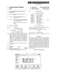
1
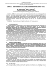
Active learning in intermediate optics through class tutorials
and concept building laboratories
Mark F. Mastersa and Timothy T. Groveb
Department of Physics
Indiana University – Purdue University Fort Wayne
Fort Wayne IN 46805, USA
ABSTRACT
We have been modifying our intermediate optics class and laboratory with a focus on improving student
learning through the use of active engagement. To facilitate this process we developed a two pronged
solution. For the classroom we created a series of tutorials to help the students use the mathematics and
techniques of derivations, apply these solutions to other problems, and develop a stronger conceptual
foundation in intermediate optics class. In the optics laboratories we developed an approach that relies upon
direct confrontation of misconceptions, predictions, collection of data to support or refute the predictions,
reconciliation, discussion, and leading questions rather than a series of detailed, cookbook-like instructions as
might be found in a traditional laboratory. Through the class and laboratory we build conceptual
understanding in subjects like image formation by lenses and mirrors, ray optics, and ultimately elliptical
polarization while fostering laboratory independence and helping students erect a new paradigm for learning.
Keywords: active learning, interactive engagement, optics tutorials, optics laboratory
1. INTRODUCTION
In 2006 we embarked on a complete revision of our optics curriculum which had not been updated for over
twenty years. These revisions involved changing how we teach the intermediate optics lecture and the
laboratory. One consideration in these modifications is that both the class and laboratory must be challenging
for senior physics students who have significant laboratory and classroom experience while not being
impossible for students who have just completed the introductory physics sequence.
The optics class and laboratory modifications follow in the wake of significant revisions of our introductory
physics classes and laboratories. In the introductory classroom we make significant use of a teaching
approach known as interactive engagement1 and peer teaching2, 3 rather than simple lecturing. Given the
measureable success of this approach at improving student understanding of the material1 and considerable
change in student attitude to learning, we felt it would be appropriate to adopt interactive engagement for the
lecture component of our intermediate optics class. However, there are difficulties with implementing
interactive engagement at an intermediate level.
2. WHAT ARE ACTIVE LEARNING AND INTERACTIVE ENGAGEMENT?
Active learning and interactive engagement (IE) means different things to different people. Active learning is
an educational technique that developed over time. It is an approach in which students are involved in, and
responsible for their own learning process. Active learning uses various methods such as interactive lecture
demonstrations4 and peer instruction2 to aid students in understanding the material under deliberation.
Adoption of this approach tends to have wider implications on the students’ learning methodology (knowledge
acquisition vs. knowledge construction, answer making vs. sense making) than simply the material under
consideration. Active learning requires the development of a habit of mind for both instructor and student. In
a
b
[email protected], http://users.ipfw.edu/masters
[email protected]
comparison, a traditional lecture class is dominated by student passivity (sitting in class and listening to
lecture) followed (hopefully) by independent active learning through homework (if properly designed) and text
reading (if the students do it). In a traditional lecture class there is no need for students to mentally engage
with the material while in class.
The term interactive engagement encompasses any and all of the variety of active learning approaches and
venues, whether in the laboratory, lecture, studio5, 6 or recitation format.7 IE classes can be characterized as
a “minds-on, hands-on” approach; the students are mentally engaged with the material in the classroom and
they must do the work in the class. The students actively discover the material and its intricacies in class. IE
has been used extensively at the introductory physics level with great success in improving student
understanding and retention of knowledge.7
An IE class is dependent upon the communication process. The instructor must be engaged in a
conversation with the whole class (not with a single questioner) and as such discovers misconceptions held
by the students. This enables the instructor to contrive situations to directly confront those misconceptions.
The instructor’s role is to set the scenario that the students investigate or consider; to determine the problem
they have to solve and then allow the students to discuss the problem in small groups. Once a group
consensus is formed, the instructor moderates a class discussion leading to a class consensus. The
instructor may direct the conversation with particular questions, but the instructor is not the source of
information. Rather, it is the class discussion that is the source of information.
3. CHALLENGES
In a traditional intermediate physics class, a significant amount of class time is devoted to the instructor
showing the students derivations of key results. These results are then applied to a variety of physical
situations. Similarly, in a traditional laboratory phenomena and classic investigations are generally
demonstrated. Unfortunately, too many students do not or cannot connect the derivation to physics, they
cannot follow the logical methodology applied through the derivation, and they are unable to apply laboratory
results and techniques to other physical situations or investigations. For example, do students know under
what situations the derivation results are valid? Can they apply the derivation techniques to different
problems? Are the students learning effectively in the laboratory if they are only following directions to
complete a demonstration?
We turned to IE in an attempt to improve learning in intermediate classes, but there are many issues. The
lack of information available regarding student misconceptions of intermediate and advanced undergraduate
topics makes this task more difficult than introductory courses. Furthermore, the nature of these courses
simply makes it harder to implement IE. Some of the problems include: 1) the concepts become more
challenging; 2) the mathematics is more challenging; 3) the students must become adept at interpreting the
mathematics physically and relating the results to reality; 4) a traditional (and important) reliance on
derivations; 5) the laboratory investigations become more technologically and conceptually complex; and 6)
these classes build upon earlier classes and any misconceptions not allayed in those classes will cause
difficulties in these.
Not to be dismayed, we have developed techniques to facilitate the use of IE in the intermediate optics venue.
Our solution has been to develop a series of tutorials for the lecture portion of the class and to completely
redesign the laboratories to engage the students. Our basic philosophy is that the students must discover the
physics. These tutorials and laboratories are available on our web page: http://users.ipfw.edu/masters/Optics
ccli project.htm.
It is important for an instructor to recognize that adopting IE in a class or laboratory may make progress
through the materials more slow than in the case of traditional lecturing. As a result, the students will have a
better mastery of the materials, improved learning skills, and better investigative skills. Regardless, we have
to reduce some of the topics often considered in lecture and in laboratory due to time constraints.
4. THE LECTURE COMPONENT OF INTERMEDIATE OPTICS
The intermediate optics course has two components: geometric optics and physical optics. These basic
optics models then provide a strong foundation for more advanced courses. Additionally, we try to help the
students become more sophisticated in their use of mathematics, to expand their ability to interpret
mathematics physically and improve their conceptual understanding of light. Rather than lecturing or showing
this material, we let the student discover the physics though tutorials.
Course outline
I.
II.
III.
Nature and models of light
a. Basic ray model
b. Basic wave model (what is a wave)
c. Photonic model
Geometric optics
a. Point and extended sources
b. Ray-tracing
c. Images
d. Optical systems
e. Aberrations
f. Mathematical formalism
Physical optics
a. Mathematical wave formalism for light and Maxwell’s equations
b. Polarization (polarizer concepts and matrix methods)
c. Interference and diffraction
The purpose of a tutorial is to help initiate the discussions. A tutorial is a document designed to lead a
student to a solution and were inspired by Lillian McDermot’s Tutorials in Introductory Physics8 and Alan van
Heuvelen’s Active Learning Problem Sets9. There are three classes of tutorials: introductory tutorials which
should be a review and deal directly with misconceptions; guided derivation tutorials in which the students are
helped through a derivation of some particular result; and application problems.
Typically, a class will use the sequence: 1) the students work in small groups on the tutorial while the
instructor circulates and asks additional questions to various groups of students (based on where they
encounter difficulties), 2) the class discusses the results, 3) resolution. Occasionally, a tutorial might be
assigned for the students to complete at home for discussion in the subsequent class.
Models of light
In geometric optics we stress use and interpretation of ray diagrams. Often, the value of ray diagrams is not
apparent to students since in class it is often rapidly replaced with equations in introductory physics.
However, ray diagrams contain a wealth of information about images, locations where images can be seen,
etc. that is not available through pure calculation. But to understand ray diagrams, the students must first
construct an idea of what is meant by a ray of light. We ask questions to guide these discussions such as:
“What is a light ray?” “What information about light does a single ray indicate? A collection of rays indicate?”
“Using a ray diagram how would one indicate that one light beam has twice the power of another?” “How
could you indicate irradiance using a ray diagram?”
Waves are a source of confusion for students. Typically students confound the amplitude of a wave with the
spatial extent or physical size of the wave. Other commonly held beliefs of light-wave misconceptions: “light
travels in waves,” “light is composed of particles that are following a wave path,” and “the static wave diagram
represents the path followed by light.” These misconceptions are also addressed through discussions.
Students are often confuse the amplitude of a wave in a diagram as indicating the spatial size of a wave. To
address the spatial extent of a wave as relative to its spatial size, we consider a longitudinal wave. In figure
1, the students are asked to plot the wave – which consists only of counting particles in a box. If we double
the height of the boxes making the wave’s spatial extent larger, do we change the amplitude of the wave? If
we double the amplitude of the wave, what has to change with the number of particles in each box?
# particles/volume
# particles/volume
B
Position
Position
D
# particles/volume
# particles/volume
C
Position
Position
Figure 1 – Tutorial fragment to assist students in understanding the wave representation and also wavelength,
frequency and how they are related. The divisions on each grid are every 5 cm. The boxes are 5cm wide by 10 cm
high by 1 cm deep (into page). A) Plot the wave form on the supplied grid. B) The same wave but a short time
later. Determine the speed, wavelength and frequency of the wave. C) Suppose you were to double the amplitude
of the wave in A, make a graph and fill in the corresponding number of particles in each box. D) Suppose the
volume of each box were doubled. What would change about the graphical representation? Would the physical
dimensions (size or spatial extent) of the wave change?
The ray and wave models of light are commonly treated as independent. However, they share some common
information which is worth exploring. Consider the question posed in Figure 2A and answered in Figure 2B.
Figures 2 – A) The wave diagram of a beam of light passing through an optical element placed at the dashed
line. Construct a ray diagram that contains some of the same information and determine, as specifically as
possible, the type of optical element. B) the solution.
Ray tracing
Once the idea of a ray diagram has been established the class works on imaging through ray tracing. Figure
3 is used to develop ray tracing formalism for a thin mirror. The students already have discussed ray
diagrams and the law of reflection as found through Fermat’s principle.
c
Figure 3 - Tutorial fragment showing the beginning of ray-tracing images for curved mirrors. The diagram showing the
bundles of parallel rays serves several purposes. First, it forces the students to recognize that not all of these rays cross
at the “focal point.” Second it is a refresher that the bundle of parallel rays constitutes light from a distant point source.
Third, distant point sources will have parallel bundles of rays that intercept the optic at different angles with respect to the
optic axis.
Making the students work with ray tracing is important so that they develop an appreciation of what they can
determine using this technique. In Figure 4 are two examples in which simple numerical calculations of image
location and a lack of understanding of ray diagrams would make the questions unanswerable. (Figure 4 B
based on techniques developed by Professor David P. Maloney10)
1
1
2
A
4
3
B
2
Figure 4 A) Describe what can each of the observers (1-4) see. B) The three ray segments shown are part of the
different principle rays used for ray tracing. Based on this diagram, specify the type of lens, its focal length, image
and object locations. Observer 1 can only see the bottom of the object. Observer 2 can see the whole object.
Estimate the size of the lens.
Derivations
An important aspect of any intermediate class is the derivation. Rather than the instructor simply showing the
students the derivations on the board and having the students copy it to their notes, we require the students
work through the derivations in peer groups. For example, in Figure 5, the beginning of a tutorial intended to
lead the students to apply the appropriate geometric construction and approximations to find the “thin mirror”
equation and to determine the location of the “focal point” is shown. After the students have been given time
to complete the tutorial, the class reconvenes and a discussion of the results of the derivation proceed, with
the instructor asking questions about various details of the derivation. Other derivation tutorials have been
developed that investigate spherical refracting surfaces, double refracting surfaces, aberrations, frustrated
internal reflection, the eye, wave equations, interference and polarization.
Intermediate Optics: Reflection from curved surfaces.
Our goal is to determine the location of the image of a point source based upon the point sources
distance from the mirror surface and the radius of curvature of the mirror.
Useful information: small angle approximation tan φ ≈ sin φ ≈ φ , cos φ ≈ 1
θ
θ
h
α’
α
s
R
φ
s’
small
Consider a point source located a distance “s” away from the surface of a convex spherical
mirror of radius R. This is shown in the diagram above. Imagine a light ray that makes an angle
α from the horizontal axis and hits the mirror some height “h” above the horizontal axis.
How would you determine where the image of the point source is formed? What is the distance
of that image from the surface of the mirror?
Is the image real or virtual?
Can you relate the angles α, α’, and θ together?
.
Can you relate the angles α, θ, and φ together?
Figure 5 –Beginning of the derivation tutorial of the thin-mirror equation. Students have to work through the
mathematics and then interpret the results.
Application
Application tutorials require the students to use the relations and concepts that they have discussed and
derived. They are not asked to simply plug in numbers, but to synthesize various techniques, methods and
concepts into a whole. Figure 4B is an example of an application tutorial in which the students have to work
with ray tracing. Another example is given in Figure 6.
Tutorial results
These tutorials serve several purposes. First, the instructor becomes apprised of the student’s
misconceptions and mathematical skills; information an instructor could not as easily obtain via lecturing.
Secondly, the students leave the class with clear notes in the form of the completed tutorial rather than the
haphazard collection of copied information. Furthermore, the critical discussion that takes place at the end of
class forces the students to put the material in their own knowledge framework. We believe (and our
observations support this) that after this class format, the majority of students have better retention of the
optics concepts and develop better mathematical skills and seem to enjoy the collaborative nature of the
classroom.
y x Birefringent optic
Linear polarizer Imagine that you have a material in which the index of refraction depends upon the polarization of the light.
Suppose that for polarizations in the y-direction the index of refraction is 1.31, while for polarization in the xdirection is 1.30. A beam of 532 nm linearly polarized light is incident upon this optical element. Immediately
following the optical element is a linear polarizer which can be rotated.
Write an expression describing a plane wave traveling in the -z-direction, with a polarization axis 15 degrees
above the x-axis. Write a second expression for the wave after the plane wave has traveled through the optical
element. Explain how you arrived at your second expression.
Make two graphs, one with the optic and one without, of the signal recorded on a detector following the linear
polarizer as the polarizer is rotated through an angle of 2π . Assume that the polarization axis of the linear
polarizer is initially aligned with the y-axis.
Are the graphs different? Why or why not.
What effect does the optical element have on polarized light?
Based on these results, if you wanted to make this optic behave as a ½ wave plate, what angle should you set
the polarization of the incident light?
Figure 6. Application tutorial for using polarization
5. LABORATORY
In the United States, the laboratory often has goals of “showing” phenomena to students, “familiarizing”
students with classic or traditional investigations, to “teach” students about the nature of scientific
investigations, to “teach” students about data acquisition and analysis, and/or to “demonstrate” to the students
what they have learned in class. With these goals, students can easily become overwhelmed because they
are confronted with new apparatus, new phenomena, new physical concepts, and new analysis techniques in
almost every laboratory. What is learned in the first laboratory investigation may not apply to laboratory
investigation eight! All this newness results in the students exclaiming “Tell me what I need to do, how to do it
and what it means!” A request with which all too many instructors are willing to comply by providing detailed
directions. This is much as Robert Millikan lamented 11 that “modern laboratory work in Physics often
degenerates into a servile following of directions …”. Fortunately, intermediate optics laboratory typically
consists of conceptually limited topics. The problem is how to avoid developing simply the “skill in
manipulation” Millikan talks about and assist the students grasp the principles or the concepts.
For intermediate optics students, we set two outcomes: developing laboratory independence, and developing
an understanding of optics such that they could design their own optical experiments. Success of achieving
each of these goals can be directly measured by providing a task for students in which we provide no
guidance; we only observe their work and behavior. Independence can be monitored by observing how they
set up an optical system (do they construct a reasonable optical system using appropriate mounts or do they
resort to sealing wax, string and stacked books), and whether they construct an appropriate optical system to
accomplish the task at hand. Student understanding can also be monitored through their discussions.
To be consistent with interactive engagement the laboratory must have two components: students discovering
optical physics through experimentation and peer teaching. We want the students to predict and test their
predictions, and to confront and articulate their misconceptions. We also want students to develop greater
independence in the laboratory to the extent that they can use their new understanding of optics complete a
project with virtually no instructor involvement beyond a project goal. This requires that the students be
familiar with the equipment as well as our progressively providing briefer instructions since giving too many
instructions runs counter to fostering student independence. To achieve these goals we have changed the
laboratory to one with a conceptual focus. Students are confronted with materials that elicit their beliefs for a
variety of optical situations on which they may have misconceptions. These situations include some that are
well documented 12-16 and others we discovered through our own observations. The students are forced to
reflect upon the validity of their beliefs in light of their observations.
To perform a reasonably complex optical experiment, we identified certain basic skills and concepts as listed
below. However, not all investigations lend themselves to this approach; we had to select certain key topics
(in particular we excluded interferometry as it always seems more demonstration based than experiment
based).
Concepts in the laboratory
•
•
•
•
•
•
•
•
•
•
Point and extended sources
What is an image?
Virtual and real images
Image location (are virtual images really
there?)
Does a real image require a screen?
Point to point correspondence between image
and object.
All rays do not pass through the focal points
Why use curved mirrors?
Polarization: what are linear, circular and
elliptical polarization
Understanding linear, ½ wave and ¼ wave
polarizers
•
•
•
•
•
•
Skills acquired in the laboratory
Optics handling skills
Use of Lenses
Imaging systems
Use of mirrors for alignment
Maintaining polarization through reflection
Use of polarizers and waveplates
Our academic semester consists of 16 weeks with a 3 hour laboratory activity each week. Every laboratory
investigation consists of four parts: a pre-laboratory assignment; class discussion about this assignment, the
laboratory activity, and a final task. The pre-laboratory assignment is completed and turned in prior to the
laboratory session and serves the following purposes: 1) to give the students a chance to think about key
topics for the upcoming activity; 2) to provide a topic of discussion for the beginning of the laboratory; and 3)
to give us (the instructors) insight into the students’ understanding.
The first 11 laboratory investigations consist of conceptual and skill building activities set up so that students
must make predictions about certain situations, collect empirical evidence to support or refute these
predictions, and reconcile the observations with their predictions. Leading questions within the activity help
bring resolution to the activity. Throughout the sequence, later activities are dependent upon the results of
earlier activities. The laboratory sequence is listed below. At the end of a laboratory period, the students are
required to complete a “final task” in which they are asked to predict the outcome of a new scenario not
covered in laboratory, and then test their prediction.
Laboratory Sequence
Week 1.
Point and extended sources – adapted from Tutorials in Physics
Week 2.
Refraction (planar refraction) [virtual images and location]
Week 3.
Image formation (curved surface refraction – using beakers) [real and virtual images]
Week 4.
Single thin lens – real images and image location using webcam
Week 5.
Single thin lens – meaning of focal point
Week 6.
Real and virtual images formed with lenses
Week 7.
Plane mirrors, images and optical alignment skills
Week 8.
Spherical mirrors and image locations
Week 9.
Polarization – linear, half-wave plate [ learning to use polarizers and what polarization means]
Week 10. Polarization – quarter-wave plate [is circularly polarized light the same as unpolarized light?]
Week 11. Polarization and reflection [maintaining polarization through reflection]
Week 12-16 - The remaining 5 weeks are spent on the optics project. Projects have been, static Fourier
transform spectrometers, frustrated total internal reflection, optical activity of corn syrup, and
the construction of a spectrograph.17
The investigations are performed by small groups (three students per group) and the students must come to a
group consensus on any answer. These groups are assigned by the faculty and change three times through
the semester. Initially, academically weaker students are paired with academically stronger students. The
students are informed that they must be able to work independently and cannot rely solely upon their
classmates for performing certain tasks. They are individually responsible for their own knowledge/skills. The
last groupings pair students with the same academic level. This means that there always is that one group
consisting entirely of students who do not seem to have been contributed significantly to their previous
groups. We have found that at least one of those students greatly improves in this environment.
Webcam
Because the laboratory requires the students collect empirical evidence of their observations, in particular for
locations of image and orientation of the image, we make extensive use of web cameras. Some of these
cameras have the lens removed. These are used either to image directly upon the sensor, or replace the lens
with a 50 mm FL lens (fixed in position relative to the sensor). The 50 mm FL lens gives the camera a fairly
small depth of field and allows it to serve the purpose determining the location of an image – even a virtual
image.
Sample activities
Figure 7 is a laboratory fragment that elicits student ideas on the issue of all of the light rays passing through
a focal point. Once they have made predictions, they have to test the situation and see if they were correct.
This type of situation provides the students with a “low-stakes” opportunity for failure, which is one of the most
critical learning tools.
Once students learn about lenses, they often see no use for those silly concave and convex mirrors. The
problem is that students often do not see any reason that they should make use of curved mirrors. In this
activity chromatic aberration becomes very apparent as the location of the image, depending upon color
changes visibly for the lens, but does not change at all for the mirror. Of course, the mirror introduces
aberration due to its use off axis. A laboratory fragment is shown for students to explore curved mirrors is
shown in Figure 8,
Lenses Part II
This section explores the nature of a focal point in regard to the rays that form an image. This section also explores the effects on an image as a result of forcing all the rays to pass through a small hole. Set up the light source, 200mm focal length lens, and a ruled screen on an optical rail. Adjust the distances between the screen, lens, and source so that a clear image appears on the screen. Place the webcam on the optical rail and get the image to appear on the monitor screen. Consider what would happen if we add an iris to this set‐up and remove the cm ruled screen. A student suggests that an iris will have a minimal effect if it is placed at the focal point of the 200mm lens (see the sketch shown below). The student explains that this works because all the rays must pass through the focal point. Do you agree or disagree with this students reasoning? EXPLAIN YOUR THOUGHTS. 200mm Lens Light Source Iris Webcam f di
do
Figure 7 – Fragment of a laboratory having the students reconsider through experimentation their ideas of image
formation and ray paths.
Set up the following. Use the point source and the 50mm diameter, 200mm focal length lens. Color filter
Lens-less
Lens
Point Source
200mm
Monitor
????? 1.50m
Adjust the lens and record the distance from the lens to the camera for each of the color lenses Make sure you readjust the focus each time. Note: you may have to adjust the shutter speed of the camera so that it doesn’t saturate. Are all of the image distances the same? Should they be? Explain. Now set up the following using a 200mm focal length concave spherical mirror. Try to keep the angle φ as small as possible. Adjust the mirror, camera distance for each color filter. Lens-less
200mm
Webcam
Monitor
focal length
?????
φ
Point Source
1.50m
Color filter
Figure 8 – A laboratory fragment in which the students discover a reason for using curved mirrors rather
than lenses.
Students generally believe the sole test for polarization is rotation of a linear polarizer indicating no
preferential polarization angle. Unfortunately, under this criteria, circularly polarized light qualifies as
“unpolarized” light. In this investigation, the students explore unpolarized light from a light bulb and then
circularly polarized light created using a quarter waveplate. In the former case, the students cannot change
the polarization to linear using a quarter waveplate. While in the latter, they are able to do so, making this
discovery valuable in persuading them that unpolarized light is not the same as circularly polarized light. In
Figure 9, a fragment of this investigation is shown.
Quartz‐
Halogen Lamp 50mm lens 632.8nm
λ/4 plate fl
Linear Photometer Polarizer in detector
hand‐turned mount By only rotating the quarter‐wave plate and linear polarizer, try to minimize the light reaching the photometer detector. Was there a significant decrease in light power at a particular polarizer angle compared to other angles? Quantify your answer using data. Remove the quarter‐wave plate and the linear polarizer without changing the position of the photometer. What does the photometer meter now read? What is the ratio of the light power reaching the detector with the quarter‐wave plate and linear polarizer (minimizing the light) compared to the light power without them? Is the light from the quartz‐halogen lamp “unpolarized”? How does the quartz‐halogen light compare with your expectations of “unpolarized” light? Connect a second λ/4 – plate to a plate rotator. Attach a piece of tape to this mount (NOT ON THE OPTICS) so that you can distinguish this quarter‐wave plate from the first. Set up the equipment as shown below. Laser First λ/4 Second λ/4 plate
Linear Photometer detector Polarizer in hand‐
turned mount
Figure 9 – Laboratory fragment in which the students explore the difference between circularly polarized light and
unpolarized light which they often confound.
Laboratory Conclusions
These laboratories provide a strong background for the students to learn, not only how to use optics, but also how optics
work. The eliciting of their thoughts in a low-stakes scenario, and providing the opportunity to acquire empirical evidence
with which to refute their predictions enables them to gain a mastery which they might not have been afforded had they
simply been following explicit directions. This is the meaning of active learning.
6. OVERALL CONCLUSIONS
These tutorials and laboratories are designed to help the students actively work with the material. However,
they cannot be used effectively without instructor to question and lead and they are not intended to be used
as such. They are meant to spur discussion between the students, to help the students discover optical
phenomena and physics and build an understanding of the same. These tutorials and laboratories are
available at (http://users.ipfw.edu/masters/Optics CCLI Project/optics_ccli_project.htm)
7. ACKNOWLEDGMENTS
This work was supported by United States National Science Foundation Grant # DUE 0410760
REFERENCES
[1]
R. Hake, Interactive-engagement Versus Traditional Methods: A Six-thousand Student Survey of Mechanics Test
Data for Introductory Physics Courses, American Journal of Physics 66 64-74 (1998).
[2]
E. Mazur, Peer Instruction: A User's Manual, Prentice Hall, Upper Saddle River, 1997.
[3]
C. Crouch and E. Mazur, Peer Instruction: Ten years of experience and results, American Journal of Physics 69
970-977 (2001).
[4]
D. Sokoloff and R. Thornton, Using Interactive Lecture Demonstrations to Create an Active Learning
Environment, The Physics Teacher 35 340 (1997).
[5]
E. Redish, J. Saul, and R. Steinberg, On the effectiveness of active-engagement microcomputer-based
laboratories, American Journal of Physics 65 45-54 (1997).
[6]
D. Sokoloff, P. Laws, and R. Thornton, RealTime Physics: active learning labs transforming the introductory
laboratory, European Journal of Physics 28 S83-S94 (2007).
[7]
R. Hake, Comment on "How do we know if we are doing a good job in physics teaching?", American Journal of
Physics 70 1058-1059 (2002).
[8]
L. C. McDermot and P. Shaffer, Tutorials in Introductory Physics, Prentice Hall, 2002.
[9]
A. V. Heuvelen, Active Learning Problem Sheets, Hayden-McNeil Publishing, 1996.
[10]
D. P. Maloney.
[11]
R. A. Millikan, Mechanics Molecular Physics and Heat, Ginn, Boston, 1903.
[12]
P. Colin and L. Viennot, Using two models in optics: Students’ difficulties and suggestions for teaching, American
Journal of Physics 69 S36-S44 (2001).
[13]
I. Galili, S. Bendall, and F. Goldberg, The effects of prior knowledge and instruction on understanding image
formation, The Journal of Research in Science Teaching 30 271-301 (1993).
[14]
I. Galili and F. Goldberg, Left-Right Conversions in a Plane Mirror, The Physics Teacher 31 463 (1993).
[15]
I. Galili, F. Goldberg, and S. Bendall, Some reflections on plane mirrors and images, The Physics Teacher 29
471 (1991).
[16]
F. Goldberg and M. L.C., An investigation of student understanding of the real image formed by a converging
lens or concave mirror, American Journal of Physics 55 108-119 (1987).
[17]
T. T. Grove and M. F. Masters, A student assembled spectrograph with a CCD detector to assist with students'
understanding of spectrometry, European Journal of Physics 28 747-753 (2007).