1
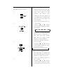
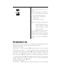
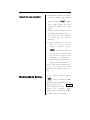
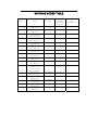
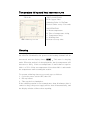
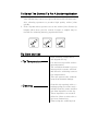
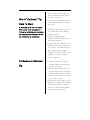
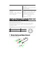
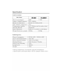
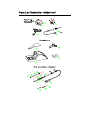
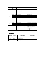
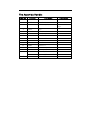
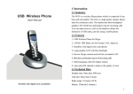
Table of Contents
Precautions …………………………………………………………………1
Names of Parts…………………… ………………………………………2
Select up & Operating station……………………………………………3
Parameters……………………………………………………………………7
Temperature rising and heat recovery curve…………………………13
Sleeping………………………………………………………………………13
Select The Correct Tip For A Soldering Station……………………14
Tip care and use……………………………………………………………14
Maintenance………………………… ……………………………………15
Calibrating the iron temperature………………………………………17
Error Message………………………………………………………………18
Trouble shooting Guide……………………………………………………18
Checking for breakage of the
heating element and cord assembly……………………………………21
Specifications………………………………………………………………24
Parts List Station/Iron Holder/Iron……………………………………25
Tips…………………………………………………………………………28
Precautions
In this instruction manual,“Warning”、
“Caution”and“Note”are defined
as follows.
! WARNING
!
WARNING: Misuse may potentially cause death of, or
serious injury to the user.
!
CAUTION: Misuse may potentially cause injury to the user
or physical damage to the objects involved.
For your own safety, be sure to comply with
these precautions.
NOTE: A NOTE indicates a procedure or point that is
important to the process being described.
! CAUTION
When the power is on ,the tip temperature is very high. Since mishandling may lead to burns or fire, be
sure to comply with the following precautions.
․Please avoid an abuse of the equipment, use the appliance only in
the described way!
․Do not touch the metallic parts near the tip.
․Do not use the product near flammable items.
․Advise other people in the work area that the unit can reach a
very high temperature and should be considered potentially dangerous.
․Turn the power off while taking breaks and when finished using the unit.
․Before replacing parts or storing the unit, turn the power off and
allow the unit to cool to room temperature.
To prevent damage to the unit and ensure a safe
working environment, be sure to comply with the
following precautions.
․Appliance shall only be used with rated voltage and frequency.
(Refer to the trademark back of equipment.)
․Don’t use or stop the use if the appliance is damaged, especially the
supply cord.
․This machine is equipped with a 3-wires grounding plug and must
be plugged into a 3-terminal grounded socket. Do not modify plug
or use an ungrounded power socket. If an extension cord is necessary, use only a 3-wire extension cord that provides grounding.
․Do not use the unit for applications other than soldering.
․Do not rap the soldering iron against the work bench to shake off
residual solder, or otherwise subject the iron to severe shocks.
․Do not modify the unit.
․Use only genuine replacement parts.
․Do not wet the unit or use and disconnect the unit when your hands
are wet and without to force the supply cord.
․The soldering process will produce smoke, so make sure the area
is well ventilated.
․While using the unit, don’t do anything which may cause bodily
harm or physical damage.
․ Children don’t recognize the risks of electrical appliances.
Therefore use or keep the appliance only under supervision of
adults and out of the reach from children.
Names of Parts
Setting up & Operating the soldering station
!
CAUTION: The sponge is compressed. It will swell when
moistened with water. Before using the unit,
dampen the sponge with the water and squeeze
it dry. Failure to do so may result in damage to
the Soldering tip.
A. Iron Holder
1. Small Cleaning Sponge
Dampen the small cleaning
sponge with water and then
squeeze it dry.
Place it in one of the openings of the iron holder base.
2. Add water to the approximate
level as shown. The small
sponge will absorb water to
keep the large sponge above
it wet at all times.
* The large sponge may be used
alone (without small sponge &
water).
3. Dampen the large cleaning
sponge and place it on the
iron holder base.
!
CAUTION: Be sure to turn off the power switch before
connecting or disconnecting the soldering iron.
Failure to do so may result in damage to the
soldering station.
B. Connections
1. Connect the cord assembly
to receptacle.
2. Place the soldering iron in
the iron holder.
3. Plug the power cord into a
power supply .Be sure to
ground the unit.
4. Turn the power switch on.
The temperature is preset at
300 ℃ or 350 ℃ at the
factory.
The heater lamp flickers
when the temperature has
stabilized.
5. Press the * button to display
the preset temperature. It
will be displayed for two
seconds.
c. Setting the Temperature
Set Temperature Normally.
!
CAUTION: Make sure the temperature of the station can be
adjusted (password is OK or the password is
initial).While setting the temperature normally,the
heating element is off.
If the “*” button is pressed for less than one second, the present
temperature setting will be shown for two seconds and then the
display will return to showing the tip temperature.
Example: 400℃ to 350℃
1.
2.
3.
4.
1. Push the “*” button and the
Hold it down for at least one
second. The left-most digit
(the 100 ’ s digit ) in the
display will flash. This
indicates that the station is
in temperature setting mode
and that the 100’s digit can
be adjusted.
2. Select the desired value for
100’s digit.
Using the “▲”or“▼”button
will change displayed value
as follows.
…
2
3
4…
Press the “*” button when the
desired value is displayed.
This will cause the middle
digit (the 10 ’ s digit) in the
display to begin flashing.
3. Select the desired value for
the 10’s digit.
Using the “▲”or“▼”button
will change displayed value
as shown below.
12t3t4t5t6t7t8t9t0
Press the “*” button.
The right (the 1’s digit) will
then begin flashing to indicate
that the 1’s digit can be set.
4. Select the desired value for
the 1’s digit.
Using the “▲”or“▼”button
will change displayed value
as shown above for the 10’s
place selection. Press the “*”
button.
Here, pressing the “*” button…
a) enter the temperature setting
into the internal memory.
b) displays the temperature
setting, and
c) starts heater control.
Note: If you turn off the power
switch during the temperature setting, setting
value will not be stored
in the memory.
If a temperature value outside
of this range is selected, the
display will return to flashing
the 100’s place. If this happens,
reenter a correct temperature
value.
Set temperature on-line
In the work, if it is necessary to set temperature quickly and the heat
elements can not be cut off, the way may be selected.
Temperature rising:
Don’t press “*” knob, and press“▲”knob directly. If so, the setting
temperature will raise 1℃ and the display window will display the
set temperature. When loosen the “▲”knob, the display window will
delay the set temperature about 2 seconds. If within 2 seconds of
time, press the “▲”knob again, the setting temperature will raise
1℃ again. If press the “▲”knob and not loose at least 1 second, the
setting temperature will rise rapidly. Till the needed temperature
reaches, then loose the “▲”knob.
Temperature dropping:
Don’t press “*” knob, and press“▼”knob directly. If so, the setting
temperature will drop 1℃ and the display window will display the set
temperature. When loose the“▼”knob, the display window will delay
the set temperature about 2 seconds. If 2 seconds later, press the
“▼”knob again, the setting temperature will drop 1℃ again. If
press the“▼”knob and not loose at least 1 second, the setting
temperature will drop rapidly. Till the needed temperature reaches,
then loose the“▼”knob.
Parameters
The station has the following parameters. Parameters setting can
be adjusted:
Setting the password.
The initial password in station ’ s memory is “000”. The setting
temperature is admitted in this state. If need to restrict the setting
temperature, the password must be changed.
Enter into setting the
password
1.Turn off the power switch.
Press and hold the “▲”and“▼
buttons simultaneously, then
turn on the power switch.
2.Continue holding down the
“▲”and“▼”button until the
display shows
3.When
the
.
display
shows
,the station is in parameter-input mode.
Input Previously
4. Press the “*” button, the
display shows
Password
,
and
the left-most digit (the 100’s
digit) in the display will flash.
This indicates the station is in
password setting mode and
the 100’s digit can be adjusted.
Using the “▲”or“▼”button
will change displayed value. Set
the password value in the
same way described in “set
temperature normally”.
After selecting the password of
three digit , press”*” button.
The input password is
Error.
The password of input
5. If the display window shows
the present setting temperature, two seconds later, the
station is in normal work state.
This indicates the password
of input is error, and the temperature setting can’t be done.
6. If the display window shows
is correct.
, this indicates the
password of input is correct.
After displaying about 4
seconds, the station comes
into normal work state, and
the setting temperature will
be admitted.
Input New Password
7. When display window is
showing
, press ”*”
button, and shows
, It
indicates the station comes
into inputting new password
state. Pressing“ ▲”or“▼”
button will change displayed
value. See “set temperature
normally”.
Repeat the new password.
8. When three digits are selected,
press”*” button, the display
window shows
again.
Now must input the new
password. Repeat the same
steps.
9. If the password is the same as
last time, the changed password is OK. The new password
is stored into the internal
memory.
10. If the password is not the
same as last time, and the
display
window
shows
, the station will need to rewrite new password.
(see the last 8-9 step). The
changing of password is
finished until the lately two
passwords are identical.
*Note: The word of password is
0 to 9, ten words. If not ,the
changed password is unsuccessful.
Working Mode Setting.
If the display window shows
, press and hold the “▲”
and“▼”buttons simultaneously,
then the display shows
X
This indicates the unit
comes into working mode
setting state, and pressing “▲”
or“▼”button will change
displayed value as shown below:
0 1 2 3 4 5 6 7
7. 6. 5. 4. 3. 2. 1. 0.
After selecting the working
mode, press”*” down. The
working mode is stored into the
internal memory.
Please refer to the “Working
Mode Table” for the meaning of
the digit displayed.
Note: “X” represents the originAl working mode digit.
Warning: The heater and soldering tips will be seriously
oxidized or damaged when
working with a high temperature.
So please choose the working
mode carefully and try to
operate
with
a
lower
temperature if possible.
WORKING MODES TABLE
WORKING
MODE
HANDLE
TEMPERATUE
AVAILABLE
MODE
RANGE
FOR HIGH
FREQUENCY
AUTO SLEEPING
AND
SWITCHING OFF
MAIN UNIT
0
200℃-420℃
60W Station
Yes
High frequency
200℃-420℃
90W Station
Yes
soldering iron
High frequency
special very large
type of soldering tip
200℃-420℃
60,90W
Yes
High frequency
50℃-600℃
90W Station
Yes
50℃-420℃
60W Station
Yes
50℃-420℃
90W Station
Yes
200℃-480℃
60W Station
Yes
200℃-480℃
90W Station
Yes
200℃-420℃
60W Station
No
200℃-420℃
90W Station
No
200℃-420℃
60,90W
No
High frequency
soldering iron
1
2
3
4
Station
tweezers stripper iron
High frequency
soldering iron
5
High frequency
soldering iron
6
High frequency
soldering iron
7
High frequency
soldering iron
0.
High frequency
soldering iron
1.
High frequency
soldering iron
2.
High frequency
tweezers or using
Station
special very large
type of soldering tip
3.
High frequency
50℃-600℃
90W Station
No
50℃-420℃
60W Station
No
50℃-420℃
90W Station
No
200℃-480℃
60W Station
No
200℃-480℃
90W Station
No
tweezers stripper
4.
High frequency
soldering iron
5.
High frequency
soldering iron
6.
High frequency
soldering iron
7.
High frequency
soldering iron
Temperature rising and heat recovery curve
TIP:2.4D
60W Soldering Station
TEST CONDITIONS
PCB: Copper Plate
Soldering Point: 1.6Xø5mm
Period: Solder every 3 Seconds
ILLUSTRATION
A: Room temperature
B: Time of temperature rising
C: Temperature drop
D: Working time
E: Heat recovery time
Sleeping
If sleeping and working mode are selected, and the soldering iron is
not used for 20 minutes, the power to the heating element will be
decreased, and the display shows
. This state is sleeping
mode. When the station is in sleeping mode, the tip temperature will
decrease to 200℃ (if the set temperature is more than or equal to
200℃) or 50℃ (if the set temperature is less than 200℃) and remain
the temperature until resuming the station.
To resume soldering, there are several ways as follows:
1. Cycle the power switch OFF, then ON.
2. Hit any button.
3. Take up the iron-handpiece.
If the soldering station is not resumed more than 40 minutes after it
comes to sleep, the power supply will be shut off automatically, and
the display window will not show anything.
To Select The Correct Tip For A Solder Application
1. Pick a tip that maximizes contact area between the tip and solder
Joint. Maximizing contact area gives the most efficient heat transfer, allowing operators to produce high quality solder joints
quickly.
2. Pick a tip that allows good access to the solder joint. Shorter tip
lengths allow more precise control. Longer or angled may be
needed for soldering densely populated boards.
Tip Care and Use
․Tip
Temperature
․Cleaning
High soldering temperatures
can degrade the tip.
Use the lowest possible soldering temperature.
The excellent thermal recovery
characteristics ensure efficient
and effective soldering event at
low temperatures.
This also protects the soldered
items from thermal damage.
Clean the tip regularly with a cleaning sponge,as oxides and carbides from the solder and flux
can form impurities on the tip.
These impurities can result in
defective joints or reduce the tip's heat conductivity.
When using the soldering iron
continuously, be sure to loosen
the tip and remove all oxides at
least once a week.
This helps prevent seizure and
reduction
of
the
tip
temperature.
․When not in use
Never leave the soldering iron
Sitting at high temperature for
long periods of time, as the tip's solder plating will become
covered with oxide, which can
greatly reduce the tip's heat
conductivity.
Wipe the tip and coat the tip
․After
with fresh solder.
use
This helps to prevent tip
oxidation.
Maintenance
Inspect and Clean the
Tip
!
Caution: Never file the tip
to remove oxide
1. Set the temperature to 250℃
2.When the temperature stabilizes, clean the tip with the cleaning sponge and check the
condition of the tip.
3. If there is black oxide on the
solder-plated portion of the
tip, apply new solder ( containing flux ) and wipe the tip
on the cleaning sponge.Repeat
until the oxide is completely
remove. Coat with new solder.
The solder protects the tip
from oxidation and prolongs
Why A” Detinned” Tip
Fails To Work
the life of the tip.
4. If the tip is deformed or heavily eroded, replace it with a
new one.
A detinned tip is one not wetted
With solder. This exposes the
a. Failure to keep the tip cover-
Plating to oxidation and degrades
ed with fresh solder during
the heat transfer efficiency of the
idling periods.
tip . Detinning is caused by :
b. High tip temperatures
c. Lack of sufficient flux in soldering operations.
d. Wiping the tip on dirty or dry
sponges and rags.( Always use a clean, wet, industrial grade, sulfur-free sponge.)
e. Impurities in the solder, iron
plating ,or on the surfaces
to be soldered.
To Restore A Detinned
Tip
1. Remove the tip from the
solder handle and allow the
tip to cool down.
2. Remove scale and oxides from the tinned area of the tip
with 80-grit abrasive polyurethane foam stock or a 100
-grit emery cloth.
3. Wrap rosin core solder (0.031
diameter or larger) around the
newly exposed iron surface,
insert the tip into the handle,
and turn on the system.
NOTE: Detinned tips are preventable with proper daily
care!
Extending Tip Life
1. Tin the tip before and after
each use. This protects the
tip from oxidizing, and prolongs the tip's life.
2. Do the job at the lowest temperature. Lower temperatures decrease tip oxidation
and are easier on the components being joined.
3. Use fine point tips only when
necessary. The plating on
fine precision tips is less durable than the plating on blunter tips.
4. Do not use the tip as a prying
tool. Bending the tip can
cause the plating to crack,
shortening tip life.
5. Use the minimum activation
flux necessary to do the job.
Higher activation flux is
more corrosive to the tip
Plating.
6. Extend tip life by switching
the system off when not in
use.
7. Don’t apply pressure to the
tip. More pressure does not
equal more heat. To improve
heat transfer, use solder to
form a
thermal
bridge
between the tip and the solder
joint.
Calibrating the Iron Temperature
The Soldering Iron should be recalibrated after changing the iron or replacing the
heating element or tip.
Method of recalibrating temperature: Use the thermometer to calibrate.
1. Set the unit’s temperature to a certain value.
2. When the temperature stabilizes, measure the tip’s temperature with
thermometer and write down the reading.
3. Press “ * ” button not loose and press the “ ▲ ”and “ ▼ ” buttons
simultaneously, the soldering station enters into calibration mode.
4. At the moment, the 100’s digit of LED display temperature is flashing. Press
the “▲” and “▼” buttons to select the value and press the “*” button to
select the digit. Press “*” button after inputting the reading. Here, the
calibration operation has been finished.
5. When inputting calibration temperature, if the value of calibration
temperature is error and the station have protection function after input the
calibration temperature and press * button, the 100’s digit of display
temperature will flash.
6. If the temperature still has deflection, you can repeat calibration in
accordance with above steps.
z We recommend to use the 191/192 thermometer for measuring the tip
temperature.
z If the unit is locked by password, it will not be able to calibrate and you
must input the right password.
Error Messages
Various error messages will be display when there is a problem with
the unit. If the following message is displayed, see the trouble
shooting guide.
If there is a possibility of a
failure in the sensor or
S - E Sensor Error
anywhere in the sensor circuit,
S - E will be displayed and
power to the soldering
iron will be cut off.
Flash the Temperature Display
Note
If power is being sent to soldering iron and the tip temperature
goes below the setting temperature about 80℃, the
temperature display will flash.
Draw your attention to this.
H - E
Heater Error
If power can’t be sent to
soldering iron, the display
window will show
. This indicates the
H - E
possibility of a heater
malfunction.
Trouble shooting Guide
!
WARNING: * Disconnect the power plug before servicing.
Failure to do so may result in electric shock.
* If the power cord is damaged, it must be replaced by the manufacturer, its service agent
or similarity qualified person in order to avoid
personal injury or damage to the unit.
Problem1.
The unit does not operate
Check1. Is the fuse blown?
․Determine why the fuse blew
and eliminate the cause, then
replace the fuse.
a. Is the inside of the iron shortcircuited?
b.Is the grounding wire touching
the heating element?
c. Is the heating element lead
twisted and short-circuited?
Check2. Is the power cord
broken?
․Replace it with a new one.
Problem2.
The tip does not heat up.
Sensor Error
S - E
is displayed.
Check3. Is the soldering iron
cord broken?
․ See how to check the
breakage of cord assembly.
Check4. Is the Sensor Element
broken?
․ See how to check the
breakage of heating and sensor
element.
Problem3.
The tip heats up intermittently.
Problem4.
Solder will not wet the tip.
Check3
Check4
Check5. Is the tip temperature
too high?
․ Set an appropriate temperature.
Check6. Is the tip cleaned?
․See “Tip Care and Use”.
Problem5.
The tip temperature is too low.
Check7. Is the tip coated with
oxide?
․See “Inspect and clean the tip”.
Check8. Is the iron calibrated
Correctly?
․ Please recalibrate.
Problem6.
Heater error
is displayed.
Check9. Is the soldering iron
cord broken?
․ See how to check the
H - E
breakage of cord assembly.
Check10. Is the heating element
broken?
․ See how to check the
breakage of heating and sensor
element.
Check11. Is there a tip on the
iron?
․ Assemble a tip on the iron.
Problem7.
Temperature
Value
displayed frequently.
are
Check12. Is the soldering iron
cord broken?
․ See how to check the
breakage of heating and sensor
element.
Check13. Is the item to be
soldered too big?
․ Use a higher out power iron
or ignore.
Problem8.
Can’t set the temperature.
Check14. Locked the button on
the panel.
․Enter into setting the password.
If you have forgot the password:
Disassemble the Front panel
(see parts list –station), plug the
power into a power supply, turn
the power switch on.
Press the “D-S” button inside
PWB (see parts list).
The password will be resumed
to “000” .
Assembly it in the reverse order
of dissassembly.
Problem9.
Soldering
iron
heats
up
continually, with the indicator
always lightening.
Check15. Is the sensor (with
polarity) connected oppositely?
˙ Resolder the sensor wire.
Check16. Is the sensor shortCircuited?
˙ Replace the sensor.
Checking for Breakage of the Heating Element and
Sensor Element and Cord Assembly
Disconnect the plug and measure the resistance value between the
connecting plug pins as follows.
If the values of ‘a’ and ‘b’are outside the above value, replace
the heating element (sensor) and/or cord assembly. Refer to
procedures 1 and 2.
If the value of ‘c’ is over the above value, remove the oxidization film
by lightly rubbing with sand-paper or steel wool the points as shown.
a. Between pins 4&5 (Heating Element)
Under
1Ω(Normal)
b. Between pins 1&2 (Sensor )
Under
10Ω(Normal)
c. Between pins 3& Tip
Under
2Ω
5
4
6
1
2
1. Broken Heating and Sensor Element
Disassembling the handle
3
1. Turn the nut (1) counterclockwise and remove the tip
enclosure (2), and the tip (3).
2. Turn the nipple(4)counterclockwise and remove it
from the iron.
3. Pull both the heating element
(10) and the cord assembly(11)
out of the handle(7).
(Toward the tip of the iron).
4.Do not use metal tools such
as pliers to remove tip or tip
enclosure from-the handle.
Measure when the heating element is at room temperature.
1. Resistance value of heating
element(White) under 1Ω.
2. Resistance value of sensor
(Red and Green) under 10Ω.
If the resistance value is not
normal, replace the heating element (Refer to the instructions
included with the replacement part.)
After replacing the heating
element.
1. Measure the resistance value
between 1) pins 4 & 1 or 2.
2) pins 5 & 1 or 2. 3) pins 6 &
1 or 2. 4) pins 6 & 4 or 5.
If it is not ∞, the heating
element and sensor are
touching. This will damage
the P.W.B.
2. Broken Soldering Iron Cord
There are two methods of
Testing the soldering iron cord
3. Replacing the fuse
2. Measure the resistance value
‘a’, ‘b’, and ‘c’ to confirm
that the leads are not twisted
and that the grounding wire is
properly connected.
3. To confirm that the clasp (9)
is clasped with heating element(10).
1. Turn the unit ON and set the
temperature control knob to
highest. Then wiggle and kink
the iron cord at various locations along its length, including
in the strain relief area. If the
LED heater lamp flickers, then
the cord needs to be replaced.
2. Check the resistance between
the pin of the plug and the
wire on the terminal.
Pin1: Blue Pin2: Red
Pin3: Shielded Conductor
Pin4: White Pin5: Black
Pin6: Green. The value should
be 0. If it is greater than 0 or
is ∞, the cord should be replaced.
1. Unplug the power cord from
the power receptacle.
2. Remove the broken fuse.
3. Remove the fuse holder.
4. Replace the fuse.
4. Put the fuse holder back in
place.
Parts List (Station/Iron Holder/Iron)
Item No
Part
No.
Part Name
1
47347
Control P.W.B.
2
47026
Driving P.W.B.
60W
47340
Driving P.W.B
90W
18008.100
Transformer
60W-100V-36V
18008.110
Transformer
60W-110V-36V
18008.220
Transformer
60W-220V-36V
18008.230
Transformer
60W-230V-36V
18069.100
Transformer
90W-100V-36V
18069.110
Transformer
90W-110V-36V
18069.220
Transformer
90W-220V-36V
18069.230
Transformer
90W-230V-36V
11002
Power cord
3 Wired Cord
11003
Power cord
3 Wired Cord & American Plug
11005
Power cord
3 Wired Cord & European Plug
47029
QK20H Handle Assembly 60W
47029.1
QK20H Handle Assembly 90W
25089.1
Fuse/1A
220V~240V
25089.2
Fuse/2A
100V~120V
3
4
5
6
Description
& Chinese Plug
Assembly(With vibrator)
Accessory :
Item No.
Part No.
Part Name
1
47031
Iron Holder
2
20011
Cleaning Sponge B6562
3
11012
Grounding Cord
4
45007
Tip or Tip Enclosure Removed Pad
Description
The Assembly Handle:
Item No
Part No.
Part Name
1
44448
Nut
2
44057.1
Tip Enclosure
3
Soldering Tip
4
42079
Nip
5
42101.7
Cord Board
6
45034
Handle Cover
7
42322.8
20H Handle
8
13006
Terminal Board
9
14009
Clasp
10
Heater Combination
11
12002
Vibrator
12
12012.1
6 Pins Plug (metal)
13
14015
Spring
14
47062
Heating Element 90W
47062.1
Heating Element 60W
47063
Sensor Element
15
Description
Refer to the Last
Page
T i p s
2
12
?1.6
200- I
200- 4C
R0.2
3
12
0.5
2
2
12
3
?
45?
2
12
200- I
?2.4
?
45?
?3
12
?4
2.5
200- 2.4D
3
R1
0.5
200- 1.6D
200- 3C
200- B
?1.2
200- 1.2D
12
2
200- J
3.5
30??
R0.2
R0.2
10
?
45?
12
?
45?
2
12
0.5
200- 2C
R0.5
12
?
45?
1.5
200- H
3
3.5
12
?2
200- B
?3
200- K
?1
?4.2
10
?
45?
1.5
200- 1C
4
12
200- SK
?0.8
3.7
0.5
200- 4.2D
2
17
200- 0.8C
?3.2
200- 3.2D
2
?4.7
12
1.2
3.5
0.5
?
45?
12
2
7.5
?
25?
15
12
1.5