1
UCam User Manual
Version 0.3
Stewart McLay
5th March 2010
Acknowledgements
Professor Vikram Dhillon who was P.I. for the UltraCam
instrument the project from which UCam was born.
The UCam development team has involved several members
of UK ATC staff. Valuable contributions were made by:
David Atkinson, Steven Beard, Derek Ives,
Stewart McLay, Chris Tierney and Andy Vick.
2
Table of Contents
1Introduction........................................................................................................................................5
1.1About UltraCam..........................................................................................................................5
1.2About ARC Controller................................................................................................................5
1.3About UK Astronomy Technology Centre.................................................................................6
1.4Acronyms And Abbreviations.....................................................................................................6
1.5Stylistic Conventions..................................................................................................................6
2Overview Of UCam Software System...............................................................................................8
2.1Hardware Set-up.........................................................................................................................8
2.2Data Flow Diagram.....................................................................................................................9
2.3Process Diagram.......................................................................................................................10
2.4Observation Terminology.........................................................................................................11
2.5Reading Out Image Data...........................................................................................................12
2.6Output Data Files......................................................................................................................13
2.6.1Raw Binary Data File Format...........................................................................................13
2.6.2Meta Data File Format......................................................................................................14
2.6.3FITS Image Data File Format...........................................................................................14
3Configuration File Overview............................................................................................................15
4How The UCam HTTP Interface Works..........................................................................................16
5How To Write A Python Script.........................................................................................................21
6Using The GUI Client Application...................................................................................................22
6.1Application Panel......................................................................................................................23
6.1.1Status Information.............................................................................................................24
6.1.2Window Layout.................................................................................................................25
6.1.3Image Settings...................................................................................................................25
6.1.4Temperature.......................................................................................................................25
6.1.5Camera..............................................................................................................................25
6.1.6Camera Applications.........................................................................................................26
6.1.7Application Parameters.....................................................................................................26
6.1.8Application........................................................................................................................26
6.2The FITS Panel.........................................................................................................................27
6.2.1FITS Header File Format..................................................................................................27
6.2.2Run Number File Name Attributes...................................................................................28
6.2.3FITS Header Editor...........................................................................................................28
6.2.4Save and Revert................................................................................................................28
6.3The Temperature Panel.............................................................................................................29
6.3.1Communications...............................................................................................................29
6.3.2Channel Attributes.............................................................................................................29
6.3.3Logging.............................................................................................................................30
6.3.4Save and Revert................................................................................................................30
6.4The Configure Panel.................................................................................................................31
6.4.1Configurable Options........................................................................................................31
6.4.2Save and Revert................................................................................................................32
6.5The Camera Panel.....................................................................................................................33
6.5.1UCam Server Interface......................................................................................................33
6.5.2Save and Revert................................................................................................................33
6.6The Debug Panel.......................................................................................................................35
7Data Sampling..................................................................................................................................36
7.1Single Raw Readout..................................................................................................................36
3
7.2Correlated Double Sample (CDS)............................................................................................36
7.3Fowler Sampling.......................................................................................................................36
7.4Non-Destructive Readout (NDR).............................................................................................36
7.4.1NDR Slope Algorithm.......................................................................................................36
7.4.2Threshold Limited NDR Slope Algorithm........................................................................36
7.4.3NDR Absolute Algorithm..................................................................................................36
7.4.4Threshold Limited NDR Absolute Algorithms.................................................................37
8Trouble Shooting..............................................................................................................................37
8.1How To Reset UCam Software.................................................................................................37
8.2How To Reload The RTAI Kernel Modules.............................................................................37
8.3How To Manually Reset The ARC Controller Hardware.........................................................37
8.4How To Debug UCam Using A Web Browser..........................................................................37
4
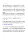
1 Introduction
The UCam software is a camera controller and data acquisition application. It is developed for use
on camera systems as part of astronomical research instrumentation and is presently in use at some
of the leading telescopes in the world today. UCam was originally developed for the UltraCam
instrument which is a high temporal resolution triple-beam CCD camera and has subsequently been
used on the WFCAM instrument which is a wide field infra-red survey camera. These are just two
examples of the wide diversity of astronomical instrumentation that UCam can support but there are
others.
The UCam software is primarily designed to make full use of the ARC controller as developed by
Astronomical Research Cameras. Although it is a highly configurable system and may be adapted in
the future for use with other camera controllers. The UCam design model is application centric
where different applications tailored for specific detectors and readout modes are downloaded and
executed on the camera controller hardware. This highly configurable application centric design is
what has enabled UCam to be an adaptable and reusable solution for several astronomical
instruments.
UCam runs on a real-time Linux operating system so it is able to provide fast imaging capabilities
for instrumentation where it is needed. It is also designed to be a server application so it can be
installed and used remotely across a network running on a standard Linux operating system. At
present UCam supports the HTTP protocol and uses the XML format for sending data packets. The
interface is simple enough to be accessible through a web browser and there are several client GUI
applications and software libraries available for interfacing with the UCam server.
This document is a user manual for the UCam software. The intended audience for this document
are end users and the technical staff who are responsible for maintaining UCam. The document
gives detailed description of how to use the UCam software as well as how it works.
1.1 About UltraCam
The UCam software system was originally designed and developed for the UltraCam instrument.
UltraCam is an ultra-fast, triple-beam CCD camera which has been designed to study one of the few
remaining unexplored regions of observational parameter space - high temporal resolution. The
camera, funded by PPARC, saw first light during 2001 and has been used on 2m, 4m and 8m class
telescopes in Australia, the Canary Islands, Chile, Greece, South Africa and Spain to study
astrophysics on the fastest time scales. More information about UltraCam can be found at
http://www.vikdhillon.staff.shef.ac.uk/ultracam.
1.2 About ARC Controller
The UCam software system was originally designed to interface with a ARC controller. The ARC
controller is developed by Astronomical Research Cameras, Inc. They design, develop and
manufacture controllers for operating CCD and infra-red imaging arrays for astronomical and
related applications. They can control a wide variety of imaging arrays in a medley of exposure and
readout modes at medium to low speeds with detector limited noise levels. The controllers include
electronic circuits, mechanical assemblies, power supplies and supporting software. They are
variously known as “Leach controllers”, "ARC controllers", as well as "SDSU controllers" for their
origins at San Diego State University. Additionally, we can supply turn-key customized systems
incorporating almost any type of scientific CCD. More information about ARC controllers can be
found at http://www.astro-cam.com.
5
1.3 About UK Astronomy Technology Centre
The UK Astronomy Technology Centre is the national centre for astronomical technology. We
design and build instruments for many of the world’s major telescopes. We also project-manage UK
and international collaborations. Our scientists carry out observational and theoretical research into
fundamental questions such as the origins of planets and of galaxies. More information is available
at http://www.roe.ac.uk/atc.
1.4 Acronyms And Abbreviations
ARC
Astronomical Research Cameras
CDS
Correlated Double Sampling
Debian
Debian Linux distribution
FITS
Flexible Image Transfer System
GUI
Graphical User Interface
HTTP
Hypertext Transfer Protocol
LAN
Local Area Network
NDR
Non Destructive Readout
OS
Operating System
RTAI
Real Time Application Interface
UltraCam
Ultra-fast, triple-beam CCD camera
URI
Uniform Resource Indicator
URL
Uniform Resource Locator
UK ATC
United Kingdom Astronomy Technology Centre
XML
Extensible Mark-up Language
1.5 Stylistic Conventions
Terminal shell commands will be displayed using Courier font with the $ representing a regular
user the shell prompt. Everything after the $ prompt will be a command entered at the terminal shell
by a user.
$ pwd
A # shell prompt is used to represent the root user shell.
# lsmod
Examples of XML data will be displayed using Courier font.
<Logging>
<Name>UCam</Name>
<Filename>/home/ucam/logfiles/ucam.log</Filename>
<Level>INFO</Level>
</Logging>
6
Python shell input and output will also be displayed using Courier font with >>> representing the
python shell prompt. Again everything after the >>> prompt will be a command entered at the
python shell by a user.
>>> import sys
>>> print sys.version
2.5.2 (r252:60911, Oct 5 2008, 19:24:49) [GCC 4.3.2] Examples of Python source code files will be framed with each line prefixed with a line number.
The line numbers are included to aid the reader but are not included in the actual source code files.
The python code be displayed using Courier font.
001 #!/usr/bin/env python 002
003 from ucam import UCam
004
005 ucam = UCam() 006 ucam.setAddress('ucamdev.roe.ac.uk') 007 ucam.setPort(9980, 9981, 9982) 008 ucam.connect()
Examples of configuration files will be framed with each line prefixed with a line number. The line
numbers are included to aid the reader but are not included in the actual configuration text files. The
text file data be displayed using Courier font.
001 logging.loggers.root.channel.class = ConsoleChannel 002 logging.loggers.app.name = Application 003 logging.loggers.app.channel = c1 004 logging.formatters.f1.class = PatternFormatter 005 logging.formatters.f1.pattern = [%p] %t 7
2 Overview Of UCam Software System
The following sub sections describe in detail how the UCam camera controller/data acquisition
works. It starts by describing the options for installing UCam on different hardware configurations.
It then goes into detail using data flow and process diagrams for describing the UCam software. It
explains the hierarchical relationship of observations, exposures and frames the basic terminology
for describing image data. It then goes into detail explaining how the image data is read out,
archived and sampled.
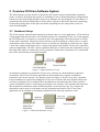
2.1 Hardware Set-up
The UCam camera controller/data acquisition software runs as a server application. UCam also has
a client application that provides a user friendly interface for controlling UCam. As UCam supports
the HTTP protocol it can easily be accessed by the client application across the network or locally
on the same workstation. This means UCam software can be installed on a either local or a remote
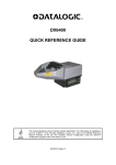
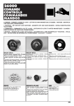
workstation on the network. This make UCam very flexible for installing at a telescope site. Figure
1 shows the simplest installation where a single workstation hosts both the UCam server and client
software applications. The ARC camera controller hardware is connected to the workstation using a
fibre link cable which is connected to a PCI board that is fitted in the workstation. The workstation
has a full Linux desktop environment installed.
Figure 1: Simple hardware set-up
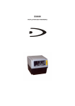
An alternative solution is to install the UCam server software on a dedicated data acquisition
workstation. The UCam GUI client application is then installed on a separate workstation
somewhere else on the network. An example is shown in figure 2. In this set-up only a standard
Linux installation is required for running the UCam server which is the more optimal solution for
real-time performance. By a standard Linux installation we mean that only the Linux operation
system is installed so there is no desktop environment or X windows. This solution also means the
data acquisition workstation can be installed anywhere in the telescope site. For example, the
instrument control room or in the dome near the instrument and camera. The UCam client
application can be installed on a desktop workstation in the telescope operator's room.
Figure 2: Advanced hardware set-up
8
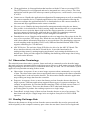
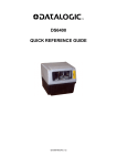
2.2 Data Flow Diagram
A data flow diagram of the UCam software is shown in figure 3. It shows how a user interacts with
the UCam software servers through a client application and how the UCam software interfaces with
the camera controller. The data flow diagram mostly uses the Yourdon notation where a circle
represents a function, a square represents an input/output, parallel lines represents data memory
storage and a cylinder represents data file storage.
Request/
Reconfigure
Application
Fetch
Executable
Application
Read
Configuration
File
Application
XML
Files
User
(Client Application)
View
Image
Sample/
Demultiplex
Image Data
Read/Write
Application
Data
Execute/
Monitor
Download
Application Application
Application
Buffer
Save Raw
Image Data
Read
Image
Data
Read
Application
Data
Execute
Application
Download
Executable
Application
Initiate
Write
Executable Application
Binary
Image Data
Buffers
Write
Raw
Data
Read
Raw
Data
Write
FITS
FITS
Files
Raw Image
Data Files
Write
Image
Data
Camera
Controller
Figure 3: UCam software data flow diagram
Each of the functions/processes in the data flow diagram are explained in more detail in the next
few paragraphs. The processes are described in the sequence that they typically occur when a new
imaging application is executed and its data is processed.
1. Fetch executable application: The user selects an application configuration file from a list.
The configuration file is read by the server into the application buffer. The top level
reconfigurable application data is uploaded to the user. The user can change parameter
values and apply other changes to the application.
2. Download executable application: The user posts the application with their changes to the
server. The application configuration received from the user is merged with the application
buffer and the application binary executable is then downloaded onto the camera controller.
3. Execute application: The user initiates the application downloaded onto the camera
controller. The application on the camera controller reads out image data from the detector.
The image data is written directly to the image data buffer memory area by the camera
controller. Whilst the application is running the user is continuously monitoring the status of
the camera controller.
4. Save raw image data: After each data buffer is written the raw image data is save to disk in a
9
data file. This frees up the buffer to be reused which is important when you are using a
circular buffer set-up. When the application has finished reading out data an XML file that
contains contextual information about the raw data is written to disk.
5. Sample/demultiplex image data: The XML file which contains information about the raw
image data describing how to sample and demultiplex the data is read. The raw image data
is then read and processed one data frame at a time. The resulting sampled images are
written to a FITS file format. These FITS file images can be read by the user to verify the
image data is acceptable.
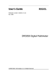
2.3 Process Diagram
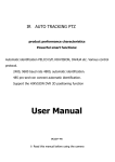
The diagram in figure 4 shows the software processes running on the CPU when UCam is running.
The client application that sends commands to the UCam servers can run on separate instrument
control workstation on the LAN or it can also be installed on the data acquisition workstation along
with the UCam software. The client application uses the HTTP networking protocol for interfacing
with the UCam servers.
Instrument Control Workstation
Client
Application
HTTP
HTTP
HTTP
Data Acquisition Workstation
Camera
Server
File Save
Server
Config
XML
Files
FIFO
Data/XML
Files
Demultiplexer
Server
FITS
Files
ARC
Controller
PCI Driver
Real Time Linux Kernel
Figure 4: UCam software process diagram
The following paragraphs describe each of the processes shown in figure 4 in more detail.
10
●
Client application: A client application that interfaces with the UCam servers using HTTP.
The HTTP protocol is well supported and can be integrated in a variety of ways. The client
application could be part of the telescope control system process, a web browser, a test script
or a GUI.
●
Camera server: Handles the application/configuration file management as well as controlling
the camera controller device. It uploads applications to the client application allowing the
client to reconfigure the application before it is downloaded on to the camera controller. It
also starts and stops applications on the camera controller.
●
File save server: Handles the image data buffer management and writing the raw data to
files on disk. A circular buffer is used for storing image data and therefore it is essential that
the file save server write the data to disk before the camera controller overwrites the
previous contents of a data buffer with fresh data. An XML file containing contextual
information about the raw image data is written alongside each data file.
●
Demultiplexer server: Samples and demultiplexes the raw image data files written by the file
save server to produce FITS image files. Reads the raw data file and the XML file associated
with it that contains information about how to process the data. The demultiplexer supports
several sampling modes including CDS, Fowler, NDR and threshold limited NDR. It also
supports windowing for CCD detectors.
●
ARC PCI driver: The real-time Linux (RTAI) device driver for the ARC PCI board. The
driver interfaces directly with the PCI board device. It provides functionality for
reading/writing memory, starting/stopping applications, and resetting the hardware to its
default state. It also provides support for handling data buffering when image data is being
read out from the detector.
2.4 Observation Terminology
The technical terms observation, exposure, frame and read are commonly used to describe image
data read out from a astronomical data acquisition system. However, these terms can mean different
things depending on the observatory or instrument where they are used. The UCam software system
applies its own particular meaning to these terms.
●
Observation: A sequence of one or more image exposures taken continuously over a period
of time. The observation starts when an application starts executing on the camera controller
and image data is read out from the detector. The observation finishes when the application
stops reading out image data from the controller.
●
Exposure: A sequence of one or more data frames read out from the detector that form a
single exposure. Different applications support different types of exposure techniques. For
example, an application for correlated double sampling (CDS) will read out two frames of
image data per exposure. These two data frames will be subtracted during the data
processing phase to produce the resulting exposure as a single image.
●
Frame/Read: A single image of data read out from the detector as part of an exposure. The
data frame/read may be a single image in its own right or form part of a CDS or NDR
exposure.
2.5 Reading Out Image Data
When raw data frames are being read out from the camera controller they need to processed and
archived quickly so the computer's memory space where the raw data is stored is freed again and
11
made available for any new data frames. If the computer's memory space is not freed in time before
the next data frame arrives that needs to use it then a bottle neck will occur. This is most likely to be
bad news for any data acquisition system as the continuous flow of data must not be interrupted
when it is being read out.
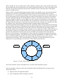
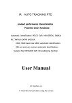
Figure 5 shows a circular buffer diagram which is likely to be familiar to any experienced software
developer. It is useful for explaining the problem in more detail. The diagram shows a ring of
buffers which is a conceptual representation of the computer's memory used to store data frames. In
the UCam system we have to processes that access the circular buffers. One process is the camera
controller which through the PCI board hardware is able to write data frames directly to the main
memory using direct memory access (DMA). It is also referred to as the producer as it produces the
image data when it writes it to the data buffer. The second process is the UCam server which reads
the image data and archives it to disk and is also referred to as the consumer as it consumes the data
by storing it away safely thereby making the buffer available again for the producer.
We will assume that the data buffers are accessed sequentially in the clockwise direction by both the
producer and the consumer. Although the direction doesn't really matter apart from the fact that both
the producer and the consumer move in the same direction. The producer writes image data to a
data buffer which is then available for the consumer to access and process and/or archive the data. If
the consumer is able to release data buffers as fast if not faster than they are being accessed by the
producer then data buffers will always be freely available to the producer when it needs them.
However, if the consumer is releasing buffers slower than they are being accessed by the producer
then eventually the producer will catch up on the consumer and find that it is unable to write image
data to a free data buffer because they all contain image data that has yet to be processed or
archived by the consumer. This is a fatal situation as it means we must either throw away good
image data or stop continuing to read out more image data from the detector.
Consumer
Producer
Figure 5: Circular buffer model
The UCam software system is designed to be a real-time data acquisition system.
There are number of factors to take into consideration when deciding how best to process and
archive data safely.
●
Exposure time for image data frames
●
Size of image data frames (number of pixels)
12
●
Processing algorithms to be applied to image data frames
●
How many image data frames must be stored continuously in memory at the same while the
data is being processed.
2.6 Output Data Files
When data is read out from the camera controller it is written to disk. Initially, two files for the raw
data are written. One file contains the raw binary image data read out from the detector and the
second file provides archive information (meta data) describing the contents of the raw data file.
The data archive information file is written in the XML file format. When the raw data is processed
an image data file in the FITS file format produced. Each of the output data files are described in
more detail in the following sections.
2.6.1 Raw Binary Data File Format
The raw data file contains the data as it is read directly from the camera controller. This data is the
binary pixel values as they have been read out from the detector. This means the pixel image data is
raw has been not been processed in any way. If the detector multiplexes the pixel values when the
detector is read out then the raw data will be stored in the same order they were multiplexed.
The raw data for each frame of image data is prefixed with a data header. The data header is written
by the camera controller at the start of each new frame. It contains essential run time information
from the controller when the data is being read out. Table ??? shows the structure and contents of a
data frame header.
Table 1: Data frame header words
...previous data frame
Status word
(2 bytes)
Engineering word
(2 bytes)
Time stamp packet
(14 bytes)
Unused header bytes
(Normally 6 bytes)
Frame number
(4 bytes)
Raw binary data
(variable size)
Exposure time
(4 bytes)
...next data frame
The data frame header status word uses bit flags for providing basic run time status information.
Table ??? shows how the bits are used and the significance of their values. The power status flag
tells us the power status of the clocks and biases on the detector when the data frame was read out.
The error status flag is a general purposes error flag in the event that anything goes wrong whilst
the data is being read out from the detector. The last frame flag tells us if this data frame is the last
one being read out as part of this sequence.
Table 2: Status word description
Status Word
Bit
Description
Value
Comment
15
Detector power status flag
0
1
Detector clocks and biases powered off
Detector clocks and biases powered on
14
Time stamp availability
0
1
Time stamp not included in header
Time stamp included in header
2 - 13
Unused
13
2
Error flag
0
1
No error status
Error status
1
Stop flag
0
1
Application completed full observation
Application terminated observation early
0
Last frame flag
0
1
Not last data frame
Last data frame
Table 3: Time stamp packet description
Time stamp packet
Bytes
Description
1-4
Seconds since epoch (1st January 1970)
5-8
Fractional second
9-12
UTC offset
13-14
Meinberg GPS status word
2.6.2 Meta Data File Format
2.6.3 FITS Image Data File Format
14
3 Configuration File Overview
Each of the UCam servers has it's own configuration file. The configuration file is read on start-up
by the server. The configuration file contains numerous options allowing the user to configure the
server in a number of ways. The server can be passed a configuration file name as a command line
argument otherwise it will try to open the default configuration (if it exists) which is named after
the server and lives in the same directory as the server executable. The default configuration file
name format is <server name>.properties. Therefore the default server configuration file names are
camera.properties, filesave.properties and demux.properties. The box below shows a sample of the
camera server configuration file.
# This is a sample configuration file for CameraServer logging.loggers.root.channel.class = ConsoleChannel logging.loggers.root.level = debug logging.loggers.app.name = Application logging.loggers.app.channel = c1 logging.formatters.f1.class = PatternFormatter logging.formatters.f1.pattern = [%p] %t #logging.formatters.f1.pattern = %Y%m%d %H:%M:%S.%c %N[%P]:%s:%q:%t logging.channels.c1.class = ConsoleChannel logging.channels.c1.formatter = f1 CameraServer.dateTimeFormat = %W, %e %b %y %H:%M:%S %Z CameraServer.device = /dev/rtai_sdsu CameraServer.applicationDirectory = /home/ucam/ucam/config/xml CameraServer.applicationListFile = list.xml CameraServer.dataDirectory = /home/ucam/ucam/data CameraServer.port = 9980 CameraServer.maxQueued = 100 CameraServer.maxThreads = 16
15
4 How The UCam HTTP Interface Works
UCam supports the HTTP protocol version 1.1. The HTTP protocol is a request/response standard
between a client and a server. UCam has three servers that are the camera, filesave and demux
applications. These HTTP servers are run continuously listening for requests from a client
application. A typical URI for a HTTP request is constructed from several parts:
http://<host name>:<port>/<path>[?query][#fragment]
●
http: Is the HTTP protocol we are using to send requests to the data acquisition workstation.
●
host name: Is the domain name or IP address for the data acquisition workstation
●
port: Is the port number for the server application running on the data acquisition
workstation. There are three server applications: camera, filesave and demux. Each server
has it's own unique port number so they can run concurrently. The port number is set in the
server's configuration file.
●
path: The path component of the URL request.
●
query: The query component of the URL request is optional depending on the path used.
●
fragment: The fragment of the URL is optional depending on the query used.
When sending HTTP requests to a UCam server the host name and port will remain consistently the
same for that server when it is running. For example, if the UCam workstation has the domain name
ucam.roe.ac.uk and the camera server is configured to use port 9980, filesave server is using port
9981 and the demux server is using port 9982 then the URL for sending a uptime request would be:
●
http://ucam.roe.ac.uk:9980/uptime
camera server uptime request
●
http://ucam.roe.ac.uk:9981/uptime
filesave server uptime request
●
http://ucam.roe.ac.uk:9982/uptime
demux server uptime request
The above HTTP requests can be tested by using a web browser and entering the URLs above into
the address bar. The uptime request will display a continually refreshing web page that displays the
time the server was started and how long it has been running or in other words the server's uptime.
This is a useful test to carry out if you want to test the server is alive.
Other types of requests can be sent to the servers but the first part of the URL for the protocol, host
name and port will always remain the same unless the configuration of the servers are altered and
the servers are restarted. The following tables provide a list of the requests supported each of the
UCam servers.
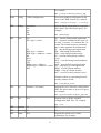
Table 4: Camera server URL requests
Method Path
Query
Description
GET
<configuration file name>
Request the server fetch the configuration
XML file whose name is given as a query.
config
16
For example:
GET /config?ccd4482_readout_app
POST
config
<XML configuration>
Post a new/updated configuration to the
server in the XML format. For example:
POST /config?<config>...</config>
GET
GET
debug
exec
instrument
obs
app
dat
sdsu
Request debug information for a specific
object that is specified by the query. For
example:
GET /debug?app
GO
EX,<type>,<value>
GO – start the timing board application
EX – exposure command where type is 0
for stop, 1 is pause, 2 is continue and 3 is
extend. The extend exposure command
take a value argument for milliseconds.
ST
ST – stop the timing board application
RM,<type>,<address>
RM – read timing board memory
WM,<type>,<address>,<value> WM – write timing board memory
RS
RS – reset the timing board (software
RCO
reset)
GOA
RCO – reset the timing board (hardware
STP
reset)
RDM,<type>,<address>
GOA – start the PCI board application
WRM,<type>,<address>,<value> STP – stop the PCI board application
RST
RDM – read PCI board memory
WRM – write PCI board memory
RST – reset PCI board (software reset)
Example of how to read timing board X
memory address 0x200:
GET /exec?RM,X,0x200
GET
get
filename=<file name>
Request the server fetch the configuration
XML file whose name is given as a query.
For example:
GET /get?filename=ccd4482_app.xml
GET
list
N/A
Request a list of all the available
configuration XML files. For example:
GET /list
GET
monitor
???
???
GET
setconfig ???
???
GET
status
Request the current server status
information. For example:
N/A
17
GET /status
GET
unsetcon ???
fig
???
GET
uptime
Request the server uptime. For example:
N/A
GET /uptime
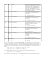
Table 5: Filesave server URL requests
Method Path
Query
Description
GET
<configuration file name>
Request the server fetch the configuration
XML file whose name is given as a query.
For example:
config
GET /config?ccd4482_readout_app
POST
config
<XML configuration>
Post a new/updated configuration to the
server in the XML format. For example:
POST /config?<config>...</config>
GET
debug
instrument
obs
app
dat
sdsu
Request debug information for a specific
object that is specified by the query. For
example:
GET /debug?app
GET
files
???
???
GET
fstatus
N/A
Request the current run number status
information
GET
setconfig ???
???
GET
start
N/A
Start a new task for reading out data for a
new observation
GET
status
N/A
Request the current server status
information. For example:
GET /status
GET
stop
N/A
Stop the data read out task
GET
unsetcon ???
fig
???
GET
uptime
Request the server uptime. For example:
N/A
GET /uptime
Table 6: Demux server URL requests
Method Path
Query
Description
18
GET
dir
N/A
Request a HTML page containing a list of
the run number data files that are available
in the data directory. All run numbers
contain links for downloading their meta
data (XML), raw data and FITS files as
well as a link for a HTML page displaying
the FITS headers contents.
GET
get_xml <run number>
Request to download the meta data file for
the run number specified in the query.
For example:
GET /get_xml?run00001
GET
get_data <run number>
Request to download the raw data file for
the run number specified in the query.
For example:
GET /get_data?run00001
GET
get_fits
<run number>
Request to download the FITS file for the
run number specified in the query.
For example:
GET /get_fits?run00001
GET
run
<run number>
Request to download the FITS file for the
run number specified in the query.
For example:
GET /run?run00001
GET
viewhea <run number>
der
Request to display a HTML page of the
FITS headers for the run number specified
in the query.
For example:
GET /viewheader?run00001
GET
uptime
N/A
Request the server uptime. For example:
GET /uptime
Here are some examples of the URL requests from the above tables. They have written in a format
that can be entered into a web browser address bar. The first example below is a write memory
command for the timing board. It will write the value 0x1234 (hexadecimal) to address 0x200 in the
X memory space. The second URL is the command to read back the value for the same memory
address.
http://ucam.roe.ac.uk:9980/exec?WM,X,0x200,0x1234
http://ucam.roe.ac.uk:9980/exec?RM,X,0x200
The following URL retrieves the list of available applications from the camera server.
http://ucam.roe.ac.uk:9980/list
From which we can select the name of an application to upload by passing its name as a query to
19
the config request.
http://ucam.roe.ac.uk:9980/config?<configuration filename>
We can retrieve status information a for camera and filesave servers using th efollowing URLs.
http://ucam.roe.ac.uk:9980/status
http://ucam.roe.ac.uk:9981/status
We can request an HTML page for the list of run numbers available in the data directory using the
following URL. The HTML page contains links for downloading the raw data, meta data and FITS
files for each run number if the file exists. It also contains a links for viewing the FITS headers in
an HTML page as well.
http://ucam.roe.ac.uk:9982/dir
20
5 How To Write A Python Script
21
6 Using The GUI Client Application
WxUCam is graphical user interface (GUI) client application for controlling the UCam server
application. WxUCam client application is written in the python programming language and uses
the wxPython cross platform GUI toolkit. At the moment wxPython supports 32-bit Microsoft
Windows, most Unix or unix-like systems, and Macintosh OS X platforms. Although at this time
UCam client application has only been tested on Linux.
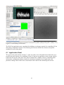
An example of a desktop environment running WxUCam and IRAF is shown in figure 6. In this
example WxUCam, shown in the bottom left corner, automatically displays FITS images using the
SAO astronomical imaging tool DS9. Although users may reconfigure WxUCam to use other image
display tools.
22
Figure 6: UCam desktop environment
The WxUCam application uses a notebook for holding several pages (panels) for controlling UCam
and setting configuration options. The following sub-sections describe the features and options
available for each of the panels.
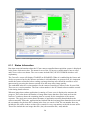
6.1 Application Panel
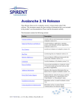
The Application panel, shown in figure 7, is the one where users will spend most of their time as it
provides the main interface for controlling UCam. UCam has an application centric design which is
reflected in the layout of the panel. The panel is divided into a number of boxes containing status
information, configuration options, buttons for initiating commands, list of applications and
parameter editing. Each of the boxes is described in more detail in the following sub-sections.
23
Figure 7: WxUCam application panel
6.1.1 Status Information
Run time status information about the UCam camera controller/data acquisition system is displayed
in the Status Information box. The status for two of the UCam server applications Camera status
and Filesave status are shown. The server states include IDLE, BUSY or ERROR which are self
explanatory.
The Controller status will display ENABLED or DISABLED. When it is enabled the the biases and
clocks are powered up for the detector and when it is disabled they are powered off. It is important
enable the camera controller before reading out image data but users should be careful to avoid
unnecessarily powering the detector on and off as this may affect image quality.
The embedded software version numbers for the camera controller are shown in the Version field.
There are two version numbers. The first version number is the PCI board software and the second
is the timing board software.
When an image data readout application is running a Frame count is displayed to measure the
progress. This value shows the number of image data frames that have been read out from the
camera. Countdown shows the remaining time in seconds for the completion of the current
exposure. The Application name shows the name of application currently downloaded on the
camera controller. When the application has finished and the last image data frame has been saved
the run number for the data file is shown in the Last run number field. The run number does not
include the file suffix as there are three files created for every run number each with its own suffix.
Those files include the raw image data file (.dat), the meta data file (.xml) and the
24
sampled/demultiplexed FITS image file (.fits).
A progress bar provides some animated feedback to the user. The progress bar provides feedback
during the execution of an application. Depending on the application read out speed it will either
show the countdown progress for single exposure or the frame count progress for observation.
A message box for providing status information to the user is shown at the bottom of the status
information box. It provides short detailed messages informing the user what UCam is doing. It is
particularly useful for helping to debug problems.
6.1.2 Window Layout
The Window Layout box shows the user the absolute positions of the window areas on the detector
when a windowing application is being used. The windows show the area of pixels on the detector
that will be read out during an observation. The window layout drawing is updated every time user
changes the X or Y application parameter values for a window. Above the window layout graphics
the full detector size is shown in X and Y pixels.
6.1.3 Image Settings
There are a several configurable options available to the user for processing and saving FITS image
data. The Image Settings box contains three drop down menus. The top menu provides exposure
processing options. These include Sum where the sum of the exposures is calculated, MEAN where
the mean of the exposures is calculated and None which prevents any further processing. The
middle menu provides FITS file format options where the user can choose to whether store
exposures in a 3-D Cube or an Extended FITS file format. The bottom menu allows user to choose
whether to store window image data in a Single FITS file or in Multiple FITS files. When
windowing image data is stored in a single FITS file they are stacked vertically in the Y axis in a
rectangular box with any unused pixels due to differing X window sizes set to zero.
6.1.4 Temperature
The Temperature box shows the current temperature sensor readings from the temperature
controller device which monitors the detector focal plane in the cryostat. The status information
shown here mirrors that shown on the main Temperature panel which provides numerous
configurable options for temperature monitoring. The status information shown on the application
panel is provided so the user is always aware of the temperature status. The temperature will flash
red and white in event of a problem where the detector focal plane temperature is deviating too far
from the set point value. Users are strongly advised to check that the temperature differential
between the cryostat and focal plane will not place the detector at risk with contamination from
condensation.
6.1.5 Camera
The Camera box provides buttons for initiating commands on the camera controller. Reset will reset
the camera controller hardware to it default state. This will result in the hardware devices rebooting
and disabling power to the detector biases and clocks.
The Initialise command will configure UCam application servers using the telescope and instrument
configuration files. It also reads back the camera controller embedded software version numbers as
shown in the Status Information box.
The Enable and Disable buttons power up and power down the biases and clocks on detector
25
respectively. The user will be prompted by a dialogue box with a warning message to check they are
sure that this is what they want to do before the command are executed.
6.1.6 Camera Applications
The Camera Applications box lists the available applications on the UCam server. The list is
updated by clicking on the Refresh button. The user can select the application they want by double
clicking on the application name or by selecting the application and then clicking on the Select
button. When an application is selected it is downloaded from the UCam server. The new
application name will appear in the Status Information box and the applications parameters are
listed in the Application Parameters box.
6.1.7 Application Parameters
When a application is selected and downloaded from the Camera Applications box the application's
parameter values are displayed in an editable grid table in the Application Parameters box. The user
can edit parameter values before the application is executed on the camera controller. Only the
parameter value column is editable the other columns are read only. Clicking on the Restore button
will restore the application parameters to their default values.
6.1.8 Application
The Application box contains two command buttons. The Execute button will upload the application
with the modified parameter values and other application data to the UCam server. The UCam
server will then perform some conditional checking on the parameter values before downloading
the application on the camera controller and executing it.
UCam supports asynchronous termination of observations. The Stop button will stop any command
or application that is currently running on the UCam server. When the stop command is issued
during the execution of an application the application will stop exposing and start reading out the
current image data frame from the detector and flag it as the last frame. The elapsed time for each
frame exposure is recorded in the image data frame header so the image data is still useful despite
the premature termination of the observation.
26
6.2 The FITS Panel
The FITS panel, shown in figure 8, allows users to customise the FITS header information included
with their FITS image data. The user can specify a file containing a formatted list of FITS header to
be included in the FITS image file for each new observation. Or they can edit a grid table for
defining FITS headers to be included in new observations. They also have the option of specifying
the run number file name attributes for the output files from the observation. The features available
on the FITS panel are described in more detail the following sub-sections.
Figure 8: WxUCam FITS panel
6.2.1 FITS Header File Format
The user can select a FITS header data file which will be read before the start of a new observation
and parsed for FITS headers that will be written into the FITS image file. Using the header file can
be toggled by clicking on the Upload FITS header data file check box.
The FITS header file is written in an XML file format. The root node for the document is
fits_header_data which contains child nodes for fits_header definitions. The fits_header nodes have
attribute values for keyword, data type, value and a use flag. STRING, FLOAT and LONG are the
only data types supported. The use flag determines whether or not the FITS header should be used
or ignored. The text value for the fits_header node is the comment associated with the header. An
example of a FITS header file is shown in figure ???.
27
<fits_header_data> <fits_header keyword="RA" type="FLOAT" use="1" value="12:34:56">Right ascension coordinates</fits_header> <fits_header keyword="DEC" type="FLOAT" use="1" value="+12:34:56">Declination coordinates</fits_header> <fits_header keyword="FILTER" type="STRING" use="1" value="J Band">Filter used during image exposure</fits_header> </fits_header_data>
6.2.2 Run Number File Name Attributes
The Prefix is an editable drop down menu where the user can enter the prefix for the output file
names. It is applied to to the file names for the raw data file, the meta data file and the FITS image
file. The Zero fill is the number of zeroes to be used as filler for the run number part of the file name
which is appended to the prefix.
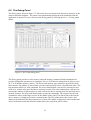
6.2.3 FITS Header Editor
The main box in the centre of the panel contains an editable grid for FITS header attributes. The
user clicks once on a grid box to select it and a second time to start editing the attribute value. It
contains columns for Use, Keyword, Type, Value and Comment attributes. These attributes should be
self explanatory for anyone who is familiar with the FITS file format. Each row define a single
FITS header. The Use check box can be toggled to determine whether or not the FITS header should
used or ignored. The Keyword is the FITS header keyword value and as per the FITS standard only
permits upper case characters and a maximum length of 8 characters. Lower case letter are
automatically converted to upper case. The data Type is a drop down menu with support for
STRING, FLOAT and LONG options. The Value should fit the data Type but when an illegal value is
entered the background will turn the red and the Use check box will be disabled. The Comment is
the FITS header comment associated with the header.
The user can add a new FITS header to the grid box by clicking on + Header or remove an existing
header by clicking on – Header. The location of the row added or removed from the grid box
depends on which row is currently selected The Up and Down buttons move the currently selected
FITS header.
6.2.4 Save and Revert
The Save button will store the information currently entered in the FITS panel to the WxUCam
application configuration file. The configuration file is read every time the WxUCam application is
started and the information is automatically entered by default into the FITS panel. Therefore the
user should click on this button whenever they want to preserve the state of the FITS panel data.
The Revert button restores the FITS panel values to those last saved in the application configuration
file.
28
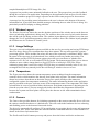
6.3 The Temperature Panel
The Temperature panel, shown in figure 9, has configurable settings for temperature monitoring. It
provides options for configuring TCP/IP communications, temperature channel attributes and
logging. The features provided on the Temperature panel are described in more detail in the
following sub-sections.
Figure 9: WxUCam temperature monitor panel
6.3.1 Communications
The Communications box is used for configuring the network interface for the temperature
controller device. It contains settings for IP Address, Port and monitoring Frequency. The user can
input the domain name or numeric value for IP Address. The Frequency determines the interval
between updates when the temperature controller is read. It is a drop down menu where the user can
set the frequency to 0.2 second, 0.5 second, 1 second or DISABLE the monitoring. The Last Update
is the latest time at which the temperature controller was successfully read. If there is a problem
reading the controller the time will change colour to red signifying that there is a problem and that
the temperature reading are no longer being updated. When the reading are resumed the colour will
default back to blue.
6.3.2 Channel Attributes
There are two channel boxes for Channel 1 and Channel 2. An Enable channel check box is
29
provided for each channel so the user can enable or disable either channel at any time. Each channel
also has a Name, Description, Temperature and a Set Point as well. The Temperature and Set Point
are read out from the temperature controller. The Name and Description are set by the user and are
important because if the channel is enabled those values will be written as FITS headers. The Name
is used for the keyword, Description is used for the comment and the Temperature is used for the
value. Altogether they form a single header entry in the FITS image file.
6.3.3 Logging
The Logging box configure the logging of temperature reading to a log file. The user can enable or
disable logging using the Enable logging check box and specify a log file name using the File text
box or use a file browser by clicking on the Browse button. The Frequency determines the interval
between successive writes to the log when the temperature status information is logged to the file.
Each log entry is written to a new line in the log file and all the values are comma separated. The
format of the logged data written to the log file is: day, date, month, year, hours:minutes:seconds,
channel 1 temperature, channel 2 temperature, channel 1 set-point, channel 2 set-point. This
makes it easy to import the log file into a spreadsheet application for generating plots.
6.3.4 Save and Revert
The Save button will store the information currently entered in the Temperature panel to the
WxUCam application configuration file. The configuration file is read every time the WxUCam
application is started and the information is automatically entered by default into the Temperature
panel. Therefore the user should click on this button whenever they want to preserve the state of the
Temperature panel data. The Revert button restores the Temperature panel values to those last saved
in the application configuration file.
30
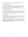
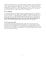
6.4 The Configure Panel
The Configure Panel, shown in figure 10, has several miscellaneous configurable settings. The
panel is not automatically displayed in the notebook when the application is started. The user can
access the Configure panel by selecting the View -> Configure menu option. The configurable
options available on the Configure panel are described in more detail the following sub-sections.
Figure 10: WxUCam configure panel
6.4.1 Configurable Options
The user can set the Telescope configuration file and the Instrument configuration file that are used
as part of the Initialise command on the Application panel. They can also set the Enable controller
application and Disable controller application that are used by the Enable and Disable commands
on the Application panel. All files are set using editable drop down menus that list the utility
applications available on the UCam server.
The Remember application parameter values check box does what it says. When the user is
downloading different applications from the UCam server the WxUCam application will remember
the last used parameter values for an application when it is reloaded.
The Download FITS file check box will automatically download FITS file from the UCam server to
the directory specified by the FITS download directory. The user can edit the directory text box or
click on the Browse button to bring up directory browser.
31
The Run post image processing command check box will automatically execute the command
specified in the Post image command after the FITS file has been downloaded. The command will
be executed in a forked sub-process. The user can enter any command they want to be executed in
the text box. Before the command is executed the application checks to see if characters RUNNUM
are entered in the text box. If so, the application will replace RUNNUM with the actual name of the
run number for the output files as reported in the Run number on the Application panel. This feature
is useful for passing the file name of the downloaded FITS file to another command for processing
or viewing the image data.
If you have IRAF and/or the SAO DS9 FITS image viewer application installed with the XPA
commands then you can automatically display a newly created FITS file with the DS9 image
display tool by entering the following command:
/usr/local/bin/xpaset -p ds9 file /home/ucam/fits/RUNNUM.fits
Or alternatively, if you have the starlink software package installed you can display FITS images
using the Gaia image display tool by entering the following command:
/home/ucam/star-nanahope/bin/gaia/gaiadisp.sh /home/ucam/fits/RUNNUM.fits
6.4.2 Save and Revert
The Save button will store the information currently entered in the Configure panel to the WxUCam
application configuration file. The configuration file is read every time the WxUCam application is
started and the information is automatically entered by default into the Configure panel. Therefore
the user should click on this button whenever they want to preserve the state of the Configure panel
data. The Revert button restores the Configure panel values to those last saved in the application
configuration file.
32
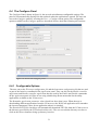
6.5 The Camera Panel
The Camera panel, shown in figure 11, has configurable settings for the UCam server network
interface. The user can tell WxUCam the UCam server's IP address and port numbers for the
camera, filesave and demux server applications. The panel is not automatically displayed in the
notebook when the application is started. The user can access the Camera panel by selecting the
View -> Camera menu option. The configurable options available on the Camera panel are
described in more detail the following sub-sections.
Figure 11: WxUCam camera panel
6.5.1 UCam Server Interface
The user can input the domain name or numeric value for the UCam server's IP Address. Also, they
can configure the port settings for each of the camera, filesave and demux servers.
6.5.2 Save and Revert
The Save button will store the information currently entered in the Camera panel to the WxUCam
application configuration file. The configuration file is read every time the WxUCam application is
started and the information is automatically entered by default into the Camera panel. Therefore the
user should click on this button whenever they want to preserve the state of the Camera panel data.
33
The Revert button restores the Camera panel values to those last saved in the application
configuration file. The Apply button applies the new camera configuration settings instantly.
34
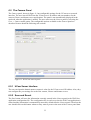
6.6 The Debug Panel
The Debug panel, shown in figure ???, allows the user to read and write directly to memory on the
camera controller hardware. The panel is not automatically displayed in the notebook when the
application is started. The user can access the Debug panel by selecting the View -> Debug menu
option.
Figure 12: WxUCam debug panel
The Debug panel provides a write memory and read memory command. Both commands have
provide configurable parameters for setting the Device (PCI board or timing board), Memory type
(X, Y or P) and the memory Address. The device and memory type options are provided by drop
down menus. The address is entered into a text box and must be given as a hexadecimal value. The
last parameter differs for each command. The write command has a text box for entering the new
value to be written at the specified device memory location. The read command has a text box for
entering the number of data words to be read out from the device starting from the specified device
memory location. The Write and Read buttons execute the commands. The response for the read
command is shown in the large text box in the middle of the panel. The data words read from the
device memory is displayed in a three column format. The left column shows the relative start
address in hexadecimal for that particular row of data. The middle column shows the hexadecimal
values of the data words and the third column shows the equivalent ASCII values.
35
7 Data Sampling
7.1 Single Raw Readout
7.2 Correlated Double Sample (CDS)
7.3 Fowler Sampling
7.4 Non-Destructive Readout (NDR)
The are four types of non-destructive readout (NDR) algorithms supported by UCam.
7.4.1 NDR Slope Algorithm
This is the algorithm for the NDR slope used in the demultiplexer process.
m=
∑ ni=1 V i {i− n1
}
2
dt × 12n n 2−1
(1)
where Vi is the voltage of the sample i, n is the total number of samples and dt is the time interval
(seconds) between the samples. The value m is the photons per pixel per second.
7.4.2 Threshold Limited NDR Slope Algorithm
This is the algorithm for the threshold limited NDR slope used in the demultiplexer process.
m=
∑ si=1 V i {i− s1
}
2
dt × 12s s2 −1
(2)
where Vi is the voltage of the sample i, s is the number of samples (minimum value is 2) where Vi is
below the threshold and dt is the time interval (seconds) between the samples. The value m is the
photons per pixel per second.
7.4.3 NDR Absolute Algorithm
This is the algorithm for the NDR absolute used in the demultiplexer process.
m=
∑ ni=1 V i {i− n1
}×n−1
2
n
12
n 2 −1
where Vi is the voltage of the sample i and n is the total number of samples. The value m is the
photons per pixel.
36
(3)
7.4.4 Threshold Limited NDR Absolute Algorithms
This is the algorithm for the threshold limited NDR absolute used in the demultiplexer process.
m=
∑ si=1 V i {i− s1
}×n−1
2
s
12
s2 −1
where Vi is the voltage of the sample i, n is the total number of samples and s is the number of
samples (minimum value is 2) where Vi is below the threshold. The value m is the photons per
pixel.
8 Trouble Shooting
8.1 How To Reset UCam Software
8.2 How To Reload The RTAI Kernel Modules
8.3 How To Manually Reset The ARC Controller Hardware
8.4 How To Debug UCam Using A Web Browser
37
(4)