1
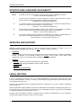
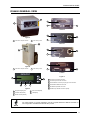
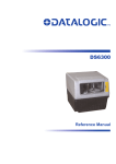
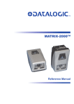
DS6400 QUICK REFERENCE GUIDE 821000786 (Rev. G) DS6400 QUICK GUIDE UPDATES AND LANGUAGE AVAILABILITY UK/US The latest drivers and documentation updates for this product are available on Internet. Log on to: www.automation.datalogic.com I Su Internet sono disponibili le versioni aggiornate di driver e documentazione di questo prodotto. Questo manuale è disponibile anche nella versione italiana. Collegarsi a: www.automation.datalogic.com F Les versions mises à jour de drivers et documentation de ce produit sont disponibles sur Internet. Ce manuel est aussi disponible en version française. Cliquez sur : www.automation.datalogic.com D Im Internet finden Sie die aktuellsten Versionen der Treiber und Dokumentation von diesem Produkt. Die deutschsprachige Version dieses Handbuches ist auch verfügbar. Adresse : www.automation.datalogic.com E En Internet están disponibles las versiones actualizadas de los drivers y documentación de este producto. También está disponible la versión en español de este manual. Dirección Internet : www.automation.datalogic.com SERVICES AND SUPPORT Datalogic provides several services as well as technical support through its website. Log on to www.automation.datalogic.com and click on the links indicated for further information: PRODUCTS Search through the links to arrive at your product page which describes specific Info, Features, Applications, Models, Accessories, and Downloads including the Genius™ utility program, which allows device configuration using a PC. It provides RS232 and Ethernet interface configuration. SERVICE - Overview - Warranty Extensions and Maintenance Agreements - Sales Network- Listing of Subsidiaries, Repair Centers, Partners - Helpdesk - Material Return Authorization LEGAL NOTICES © 2003 - 2010 Datalogic Automation S.r.l. ALL RIGHTS RESERVED. Protected to the fullest extent under U.S. and international laws. Copying, or altering of this document is prohibited without express written consent from Datalogic Automation S.r.l. Datalogic and the Datalogic logo are registered trademarks of Datalogic S.p.A. in many countries, including the U.S.A. and the E.U. Genius, PackTrack, Step-a-Head, FLASH, ACR, and ID-NET are trademarks of Datalogic Automation S.r.l. All other brand and product names mentioned herein are for identification purposes only and may be trademarks or registered trademarks of their respective owners. Datalogic shall not be liable for technical or editorial errors or omissions contained herein, nor for incidental or consequential damages resulting from the use of this material. 2 DS6400 QUICK GUIDE DS6400 GENERAL VIEW 2 3 1 2 1 Standard 3 4 Figure A 1 Laser Beam Output Window 2 2 Laser Safety Label Ethernet 2 3 1 5 2 DeviceNet 3 Figure B 1 Laser Beam Output Window 2 2 Laser Safety Label 6 Profibus Figure D 5 1 1 Lonworks 9-pin Male Connector 2 Lonworks 9-pin Female Connector 3 Serial Interface and I/O 25-pin (26-pin) male Connector 4 3 2 4 RJ45 Modular Ethernet Connector 5 DeviceNet 5-pin Male Connector 6 Profibus 9-pin Female Connector (white) Figure C 1 Programming Keypad 4 Power On LED (Red) 2 TX Data LED (Green) 5 LCD Display 3 Phase On LED (Yellow) For further details on product installation, see the complete Reference Manual available on the configuration CD-ROM included with this product. NOTE 3 DS6400 QUICK GUIDE CONNECTIVITY Examples of the most common system layouts are shown in this section, for additional layouts refer to the Reference Manual. Local Lonworks Networks CAB-Sxx CBX100** CAB-610x BT-6000 Local Host Master I/O, AUX Slave 1 P.S.* BT-6000 PWR-120 CAB-63xx * P.S. (Presence Sensor) connected to Input 1 (External Trigger/PS) input. ** CBX100 jumper set to accept scanner power. Small Synchronized Network with 2 Readers CAB-610x BT-6000 CBX100** Slave 3 Slave 4 CAB-610x Local Host I/O, AUX, Encoder*** Master P.S.* Slave 2 CAB-610x Slave 1 PWR-240 CAB-650x CAB-F0x BTK-8102 CAB-63xx CAB-63xx Note: In a mixed 8K and 6K family scanner network, only the 8K family scanner can be Master * P.S. (Presence Sensor) connected to Input 1 (External Trigger/PS) input. ** CBX100 jumper set to accept scanner power. *** Encoder connected to Input 2 (Encoder) input. Synchronized Network with DS8100A Master and 6K Family Slaves - Serial Host 4 DS6400 QUICK GUIDE Fieldbus CAB-610x BT-6000 CBX100** Slave 3 Slave 4 CAB-610x Remote Host I/O, AUX, Encoder*** P.S.* Slave 2 Slave 1 Master* PWR-240 CAB-610x CAB-610x CAB-F0x CAB-63xx CAB-63xx * P.S. (Presence Sensor) connected to Input 1 (External Trigger/PS) input. ** CBX100 jumper set to accept scanner power. *** Encoder connected to Input 2 (Encoder) input. Synchronized Network with DS6400 Master and 6K Family Slaves - Fieldbus Host P.S.* Slave 3 P.S.* Slave 2 BT-6000 CAB-611x PG6000 CAB-Sxx P.S.* Slave 1 CAB-611x Master CAB-611x PG6000 CAB-Sxx P.S.* BT-6000 PG6000 PG6000 CAB-Sxx CAB-Sxx Local Host CBX100 * Each P.S. (Presence Sensor) connected to Input 1 (External Trigger/PS) input. Multidata Network NETWORK TERMINATION When building a local Lonworks system the network must be properly terminated by positioning a BT-6000 terminator on the DS6400 master reader (BT-6000 female side) and on the last slave reader (BT-6000 male side). to Master to Slave 9-pin female 9-pin male BT-6000 Network Terminator 5 DS6400 QUICK GUIDE ELECTRICAL CONNECTIONS The details of the connector pins are indicated in the following tables: The table below gives the pinout of the CBX100/CBX500 terminal block connectors. Use this pinout when the DS6400 reader is connected by means of the CBX100/CBX500: CBX100/500 Terminal Block Connectors Power Vdc GND Earth Power Supply Input Voltage + Power Supply Input Voltage Protection Earth Ground Inputs +V -V I1A I1B I2A I2B I3A I4A I34B Power Source – Inputs Power Reference – Inputs EXT TRIG/PS A (polarity insensitive) for PS EXT TRIG/PS B (polarity insensitive) for PS IN 2/ENC A (polarity insensitive) for Encoder IN 2/ENC B (polarity insensitive) for Encoder IN 3A (polarity insensitive) (only with CBX500) IN 4A (polarity insensitive) (only with CBX500) IN 3B/IN 4B Reference (polarity insensitive) (only with CBX500) +V -V O1+ O1O2+ O2O3A O3B Power Source - Outputs Power Reference - Outputs OUT 1+ OUT 1OUT 2+ OUT 2OUT 3A (polarity insensitive) (only with CBX500) OUT 3B (polarity insensitive) (only with CBX500) Outputs Auxiliary Interface TX RX SGND Auxiliary Interface TX Auxiliary Interface RX Auxiliary Interface Reference Shield Shield Network Cable Shield RS232 TX RTS RX CTS SGND Main Interface RS485 Full-Duplex TX+ TX*RX+ *RXSGND RS485 Half-Duplex RTX+ RTX- SGND * Do not leave floating, see Reference Manual for connection details. Do not connect GND and SGND to different (external) ground references. GND and SGND are internally connected through filtering circuitry which can be permanently damaged if subjected to voltage drops over 0.8 Vdc. CAUTION 6 DS6400 QUICK GUIDE The DS6400 scanner provides a 25-pin (26-pin for Fieldbus models) male D-sub connector for connection to power supply, Host interface (Main and Aux), and input/output signals. 25-pin / 26-pin D-Sub Connector Pinout Pin Name Function Chassis - internally connected to GND 1 CHASSIS Cable shield connected to chassis 20 RXAUX Receive data of auxiliary RS232 (referred to GND) 21 TXAUX Transmit data of auxiliary RS232 (referred to GND) 8 OUT 1+ Configurable digital output 1 – positive pin 1 13 22 OUT 1Configurable digital output 1 – negative pin 11 OUT 2+ Configurable digital output 2 – positive pin 25 14 12 OUT 2Configurable digital output 2 – negative pin 25-pin male D-sub Connector 16 OUT 3A Configurable digital output 3 – polarity insensitive 17 OUT 3B Configurable digital output 3 – polarity insensitive 18 EXT_TRIG/PS A External trigger (polarity insensitive) for PS 19 EXT_TRIG/PS B External trigger (polarity insensitive) for PS 9 1 10 18 6 IN2/ENC A Input signal 2 (polarity insensitive) for Encoder 19 26 10 IN2/ENC B Input signal 2 (polarity insensitive) for Encoder 14 IN3A Input signal 3 (polarity insensitive) 26-pin male D-sub Connector 15 IN4A Input signal 4 (polarity insensitive) 24 IN_REF Common reference of IN3 and IN4 (polarity insensitive) 9, 13 VS Supply voltage – positive pin 23, 25, 26 GND Supply voltage – negative pin Main Interface Pin RS232 RS485 Full-Duplex RS485 Half-Duplex 2 3 4 5 7 TX RX RTS CTS GND_ISO TX485+ * RX485+ TX485* RX485GND_ISO RTX485+ RTX485GND_ISO * Do not leave floating, see Reference Manual for connection details. Two 9-pin connector(s) provide access to the scanner’s local Lonworks network. The Master/Slave model has two Lonworks connectors used for both input and output connections to build a multi-sided or omni-station system. The Fieldbus models have one Lonworks connector and therefore can be used in a Lonworks network only as a Master. 9-pin Lonworks Connector Pinout Pin Name 1 CHASSIS 9 2 6 3 4 5 7 8 VS GND VS_I/O Ref_I/O SYS_ENC_I/O SYS_I/O LON A LON B Function Cable shield internally connected by capacitor to chassis Supply voltage – positive pin Supply voltage – negative pin Supply voltage of I/O circuit Reference voltage of I/O circuit System signal System signal Lonworks line (polarity insensitive) Lonworks line (polarity insensitive) 1 5 9 6 Female 5 1 6 9 Male (M/S model only) 9-pin Local Lonworks Connectors 7 DS6400 QUICK GUIDE Ethernet Model RJ45 Modular Connector HUB / SWITCH DS6400 T X+ 1 1 T X- 2 2 RX+ 3 3 n. c. 4 4 n. c. 5 5 RX- 6 6 n. c. 7 7 n. c. 8 8 8 1 RJ45 Female Connector n. c. = not connected DeviceNet Model When using DeviceNet, the Main serial interface is disabled and must not be physically connected. NOTE 5-pin DeviceNet Connector Pinout Pin 2 5 1 4 3 Name V+ CAN_L SHIELD CAN_H V- NOTE Function Supply voltage – positive pin CAN bus data line – L Shield CAN bus data line – H Supply voltage – negative pin 4 3 1 2 5 5-pin male DeviceNet Connector The power supplied on pin V+ and V- is used only to propagate power to the section of the DeviceNet board directly connected to the Bus. It is completely isolated from the DS6400 power which must be supplied on pin 9, 13 and pin 23, 25 of the 26-pin Main/Aux connector. Profibus Model 9-pin Profibus Connector Pin 1 2 3 4 5 6 7 8 9 8 Name Shield Free B-LINE (RxD/TxD-P) CNTR-P DGND +5 V Free A-LINE (RxD/TxD-N) CNTR-N Function Shield, Protective Ground resp. (optional) Received/Transmitted Data-P Repeater Control Signal (optional, RS485 level) Data Ground (M5V) Voltage Plus (P5V) Received/Transmitted Data Repeater Control Signal 1 5 9 6 9-pin female Profibus Connector (white) DS6400 QUICK GUIDE APPENDIX TECHNICAL FEATURES ELECTRICAL FEATURES Supply Voltage Power Consumption Common Communication Interfaces Model-Dependent Communication Interfaces Inputs Ext. Trigger 1, Encoder 2 aux. digital inputs Outputs 3 software programmable digital outputs 15 to 30 Vdc 1.0 to 0.5 A; 15 W typical 1.5 to 0.7 A; 24 W Max. (including startup current) Baud Rate Main RS232 RS485 full-duplex RS485 half-duplex Auxiliary RS232 1200 to 115200 1200 to 115200 Other Lonworks Ethernet DeviceNet Profibus 1.25 Mb/s 100 Mb/s up to 500 Kb/s up to 12 Mb/s (optocoupled NPN or PNP) (optocoupled) OPTICAL FEATURES Light Receiver Wavelength Safety Class Laser Control Avalanche photodiode 630 to 680 nm Class 2 - EN60825-1; Class II - CDRH Security system to turn laser off in case of motor slow down READING FEATURES Scan rate Maximum Resolution Max. Reading Distance Max. Reading Width Max. Depth of Field 600 to 1200 scans/s (see reading diagrams) USER INTERFACE LCD Display Keypad LED Indicators 2 lines by 16 characters LCD 3 keys Power On (red) Phase On (yellow) TX Data (green) 9 DS6400 QUICK GUIDE SOFTWARE FEATURES Readable Codes Code Selection Headers and Terminators Operating Modes Configuration Modes Parameter Storage Interleaved 2/5 Code 39 Standard Codabar Code 128 EAN 128 Code 93 (standard and full ASCII) EAN/UPC (including Add-on 2 and Add-on 5) GS1 DataBar (including Limited and Expanded) Up to 10 codes during one reading phase Up to 128-bytes headers and 128-bytes terminators On Line, Serial On Line, Automatic, Test, PackTrack™, Continuous Genius™ utility program Non-volatile internal FLASH ENVIRONMENTAL FEATURES Operating Temperature Storage Temperature Humidity Ambient Light Immunity Vibration Resistance EN 60068-2-6 2 hours on each axis 0° to +40 °C (+32° to +104 °F) -20° to +70 °C (-4° to +158 °F) 90% non condensing 3500 lux 14 mm @ 2 to 10 Hz; 1.5 mm @ 13 to 55 Hz; 2 g @ 70 to 200 Hz Shock Resistance EN 60068-2-27 3 shocks on each axis 30 g; 11 ms Protection Class – EN 60529 Ethernet models IP50 Master/Slave models IP64 PHYSICAL FEATURES Standard models Oscillating Mirror models Mechanical Dimensions 110x113x99 (4.33x4.45x3.9) 1.5 kg (3.3 lb) 113x180x104.5 (4.45x7.08x4.11) 2.0 kg (4.4 lb) Weight MODEL DESCRIPTION DS6400 - 10X - 0YY Decoder Model (Base) Optical Model (Head) 0 = Standard 5 = Oscillating Mirror 10 10 = Master/Slave 11 = Profibus 12 = Ethernet 15 = Devicenet DS6400 QUICK GUIDE ACCESSORIES Name Description Part Number Single unit power supply (US) Single unit power supply (UK) Single unit power supply (EU) J-box power unit 110/230 VAC 24 V 120 W J-box power unit 110/230 VAC 24 V 240 W J-box power unit 110/230 VAC 24 V 480 W 93ACC1718 93ACC1719 93ACC1720 93ACC1530 93ACC1070 93ACC1850 Bus terminator 9-pin scanner/scanner connection cable 1 m 9-pin scanner/scanner connection cable 2 m 9-pin scanner/scanner connection cable 5 m 9-pin scanner to scanner no power cable 2 m 9-pin scanner to scanner no power cable 5 m 25-pin power cable Fam 6k 5 m 25-pin power cable Fam 6k 10 m STD cable to CBX 1 m (25-pin to 25-pin) STD cable to CBX 2 m (25-pin to 25-pin) STD cable to CBX 5 m (25-pin to 25-pin) STD cable to CBX 10 m (25-pin to 25-pin) 6K-8K FBUS cable to CBX 1 m (26-pin to 25-pin) 6K-8K FBUS cable to CBX 2 m (26-pin to 25-pin) 6K-8K FBUS cable to CBX 5 m (26-pin to 25-pin) Fam 6K-8K cross cable 2.5 m (9-pin to 17-pin) Fam 6K-8K cross cable 5 m (9-pin to 17-pin) 93A051299 93A051220 93A051230 93A051240 93A051224 93A051225 93ACC1768 93ACC1752 93A051351 93A051352 93A051353 93A051354 93A051355 93A051356 93A051357 93A051288 93A051289 Supervisor (up to 5 arrays) Supervisor (up to 10 arrays) Supervisor (up to 20 arrays) Supervisor (up to 32 arrays) Supervisor (up to 64 arrays) Supervisor (up to 128 arrays) Supervisor (up to 256 arrays) 93A101014 93A101015 93A101016 93A101017 93A101018 93A101019 93A101020 90° mirror 90° mirror close distance 93A201100 93A201102 Compact Connection Box Modular Connection Box Gateway Connection Box Backup Module DIN Rail Adapters for CBX Bosch Adapters for CBX Two Cable Glands Panel 93A301067 93A301068 93A301077 93ACC1808 93ACC1821 93ACC1822 93ACC1847 Photocell kit – PNP (PH-1) Photocell kit – NPN Optical encoder kit (10 m cable + spring) Optical encoder kit + 10 m cable 93ACC1791 93ACC1728 93ACC1770 93ACC1600 Fast bracket kit (2 pcs) Mounting bracket kit (5 pcs) for multisided stations 93ACC1721 890001020 Power Supplies PG6002 PG6001 PG6000 PWR-120 PWR-240 PWR-480A Cables and Terminators BT-6000 CAB-6101 CAB-6102 CAB-6105 CAB-6112 CAB-6115 CAB-6305 CAB-6310 CAB-S01 CAB-S02 CAB-S05 CAB-S10 CAB-F01 CAB-F02 CAB-F05 CAB-6502 CAB-6505 Software Management Datalogic WebSentinel-005 Datalogic WebSentinel-010 Datalogic WebSentinel-020 Datalogic WebSentinel-032 Datalogic WebSentinel-064 Datalogic WebSentinel-128 Datalogic WebSentinel-256 Mirrors GFC-60 GFC-600 * Connection Boxes CBX100 CBX500 CBX800 BM100 BA100 BA200 BA900 Sensors MEP-593 MEP-543 OEK-2 OEK-1 Brackets FBK-6000 US-60 * DS6400 application software does not support any of the CBX500 Host Interface Module accessories nor the BM150 Display accessory. Use the CBX800 Gateway for Host Interface Applications, (Fieldbus and non Fieldbus). 11 DS6400 QUICK GUIDE OSCILLATING MIRROR MODEL 1 Figure A 1 Laser Beam Output Window Oscillating mirror models are used when coverage of a large reading area is required, mainly in picket fence applications. The DS6400 scanner mounts a dedicated optic head with integrated oscillating mirror driven by a linear motor. The speed, precision, repeatability, and reliability of this driving technology assure high level performance. The new oscillating mirror is completely software controlled and software programmable. The Genius™ software tool allows adjusting the linear motor speed (oscillating frequency) and the upper and lower limits of the oscillation by defining the top and bottom line limit angles. When the oscillating mirror is programmed to read barcode labels at very small angles, position the reader to assure at least 10° for the Skew angle (see DS6400 Reference Manual). This angle refers to the most inclined or external laser line, so that all other laser lines assure more than 10° Skew. This avoids the direct reflection of the laser light emitted by the reader. 10° Oscillating Mirror Skew Angle Otherwise, the scanner can be mounted at an angle of inclination of 17.5° in order to attain symmetrical deflection ranges. 10 7. 5° 17.5° Oscillating Mirror Reading Position In the above case, the zone where the scan line is perpendicular to the reflecting surface corresponds to a neutral zone at the center of the reading field. 12 DS6400 QUICK GUIDE The mirror can be deflected up to 40°. Oscillation with respect to the output window median axis is asymmetrical (see figure below). ° 37.5 40° -2.5° 0° Oscillating Mirror Maximum Aperture and Asymmetry By configuring the oscillating speed up to the maximum value of 19 Hz, raster emulation can be performed for reading fast moving objects. Hz Max. Aperture 0-5 6-10 11-15 16-19 40° 30° 20° 10° By limiting the raster width to the minimum necessary, the number of scans on the reading surface is increased. NOTE Oscillating angles are selected in software where the minimum and maximum angles correspond to –2.5° and +37.5°. +37.5° +17.5° The scanner can be tilted in order for the 17.5° software setting to correspond with the 0° horizontal plane. -2.5° Oscillating Mirror Extreme Angle Positions These models provide higher scanning speed (1200 scans/sec) compared to standard models and the reading performance is not adversely effected by the oscillating mirror. The example represents the selection of an angle of +10° for the bottom line and an angle of +20° for the top line (see figure beside). +37.5° +27.5° +17.5° Oscillating Mode 13 DS6400 QUICK GUIDE MECHANICAL INSTALLATION The DS6400 reader can be positioned and installed in the best way possible as a result of the patented Step-AHeadTM feature. Thanks to the separation between Head and Base, you can modify the orientation of the decoder base, and therefore display-keypad and connector panels, while keeping the optic head in the correct reading position. The reading head and the decoder base can be rotated independently from each other allowing the installation even in the most critical locations. To rotate the head follow the given procedure: Head Screws 1. detach the head from the base by unscrewing the four fixing screws; 2. rotate the head in the desired position; 3. loosen but don’t remove the two screws on top of the head; 4. affix the head onto the base carefully aligning the four fixing screws and progressively tightening them about half-way; 5. completely tighten the two screws on top of the head; 6. completely tighten the four fixing screws. Fixing Screw (4) Step-A-Head™ Feature The following diagrams give the overall dimensions of the reader standard model, oscillating mirror model and mounting bracket. They may be used for their installation: 16.5 0.65 85 3.34 42 1.65 10 0.4 50 82 1.96 3.22 2 N° °2 .1 N Ø40.16 Ø = = mm inch 113 4.45 130 5.12 106° = 50 1.96 72 2.83 100 3.93 = 73.2 2.88 36 1.41 99 3.90 30 1.18 74 2.85 TS LO S 4 S OT N° 4 SL 4.5 8 N° 0.1 126 4.96 76 2.99 4 0.15 35 1.37 30 1.18 60 2.36 82 3.22 25 50 1.96 0.98 20 18 0.78 0.71 N°2 22 0.86 O TS °2 SL S 8.5 N °2 SLOT N 0.33 .5 Ø 8 . 33 Ø0 mm inch 110 4.33 DS6400 Overall Dimensions ST-237 Mounting Bracket Overall Dimensions 30 1.18 42 1.65 18 0.71 4 0.15 50 1.96 35 1.37 82 3.22 50 1.96 20 0.78 5.11 130 16.5 0.65 Ø4.1 0.16 R1 99 3.90 63.5 2.50 104.5 4.11 22 0.86 25 0.98 60 2.36 85 3.35 10 0.4 11 0.43 14 0.55 69 2.72 56 2.20 50 1.96 72 2.83 100 3.93 114 4.48 R5 11 0.43 14 0.55 180 7.08 DS6400 Oscillating Mirror Model Overall Dimensions 14 36 1.41 R22 75 2.95 113 4.45 102 4.01 110.3 4.34 R36 mm inch Ø8 mm inch .5 ST-210 Mounting Bracket Overall Dimensions DS6400 QUICK GUIDE 16° Skew Positioning The DS6400 scanner is mounted on the ST-237 106° mounting bracket which guarantees a built-in Skew angle (S in the figure below) of 16° with respect to the frame plane (typically the Skew angle should be between 10° 20°). This avoids the direct reflection of the laser light emitted by the scanner. Furthermore, the bracket guides allow adjusting the Tilt angle (T in the figure below, which is typically 0°) for the best scanner orientation: T S Conveyor Direction 45° Skew Positioning The DS6400 scanner is mounted on the ST-210 90° mounting bracket. By adjusting the mounting bracket guides, reach 45° for the Skew angle (S in the figure below) to avoid the direct reflection of the laser light emitted by the scanner: 45° S If using the 45° Skew installation, the scanner reading performance is not guaranteed to match that measured for the standard installation with Skew angle between 10° - 20° (see reading diagrams). CAUTION The ST-210 mounting bracket is an accessory of the DS6400 standard model available in the US-60 kit (890001020). NOTE WARNING When installing several scanners, take care to position them correctly so that no laser beam enters the reading window perpendicularly and at the same level of the output beam of the other scanners. This condition could occur more frequently for side mounted applications. If these precautions are not followed, it may occur that the laser of the blinded scanner starts blinking due to an internal circuit which temporarily turns the laser off when detecting a power anomaly. To resolve this problem, it is sufficient to slightly change the inclination and position of one of the two scanners involved. 15 DS6400 QUICK GUIDE FLASH™ Dynamic Focus: The DS6400 has an innovative linear motor designed to control the focus position of the scanner via software. This dynamic system, called FLASH™, is able to move the focus position rail to rail, from the minimum position to the maximum position. The FLASH™ functionalities (i.e. the driving modes of the linear motor) are programmed via the Genius™ software tool and can operate in the following modes: - Fixed mode: the focus is set to the desired position via software (expressed in cm); - Continuous mode: the focus position is continuously running from a minimum position to a maximum position with a defined frequency; - Triggered mode: the focus position can be set depending on the received external input (photocell, barrier, serial message, etc.); - D-Flash™ mode: the focus position can be set depending on the measured distance between the scanner and the scanned object. This is the most innovative and flexible function that makes different software implementations possible. The D-Flash™ development has been based on the minimum distance detected. Thus, it can apply to the widest variety of applications. Further developments of D-Flash™ will be provided according to the specific application needs. READING CONDITIONS ANSI Grade B minimum 800 scans/sec The following tables describe the requirements for standard applications. Conveyor Speed (m/s) 2/5 Interleaved Code Resolution (mm) 0.25 0.30 0.33 0.38 0.50 0.72 1.00 0.5 10 12 13 14 18 24 33 1 12 14 14 16 19 25 34 Minimum Code Height for ACR Reading (mm) 45° 30° 1.5 2 2.5 3 0.5 1 1.5 2 14 16 18 20 7 9 10 12 15 17 19 21 8 9 11 12 16 18 20 22 8 10 11 13 18 19 21 23 9 11 12 14 21 23 25 26 11 12 14 15 27 28 30 32 15 16 17 19 35 36 38 40 20 21 22 23 2.5 13 14 14 15 17 20 25 3 15 15 16 17 18 22 26 2.5 12 12 13 13 14 17 20 3 13 14 14 15 16 18 21 Ratio 3:1 Table 1 Conveyor Speed (m/s) Code 39 Code Resolution (mm) 0.25 0.30 0.33 0.38 0.50 0.72 1.00 0.5 9 10 11 12 15 20 27 1 10 11 12 13 16 21 28 Minimum Code Height for ACR Reading (mm) 45° 30° 1.5 2 2.5 3 0.5 1 1.5 2 12 14 16 17 6 7 9 10 13 15 17 18 7 8 9 11 13 15 17 19 7 8 10 11 14 16 18 20 8 9 10 12 17 18 20 22 10 10 11 13 22 23 24 26 13 13 14 15 29 30 31 32 17 17 18 19 Ratio 3:1; Interdigit = Module Size Table 2 16 DS6400 QUICK GUIDE Conveyor Speed (m/s) Code 128 – Ean 128 Code Resolution (mm) 0.25 0.30 0.33 0.38 0.50 0.72 1.00 0.5 8 8 9 10 12 16 22 1 9 10 11 11 13 17 23 Minimum Code Height for ACR Reading (mm) 45° 30° 1.5 2 2.5 3 0.5 1 1.5 2 11 13 15 17 5 7 8 10 12 14 16 18 6 7 9 10 13 14 16 18 6 8 9 11 13 15 17 19 7 8 10 11 15 17 19 21 8 9 11 12 19 21 22 24 10 11 13 14 24 25 27 29 13 14 15 17 2.5 11 12 12 13 14 16 18 3 13 13 14 14 15 17 20 2.5 11 12 12 13 14 16 18 3 13 13 14 14 15 17 20 2.5 11 11 12 12 13 14 16 3 12 13 13 13 14 16 18 Table 3 Conveyor Speed (m/s) Codabar Code Resolution (mm) 0.25 0.30 0.33 0.38 0.50 0.72 1.00 0.5 8 9 9 10 13 17 23 1 9 10 11 11 14 18 24 Minimum Code Height for ACR Reading (mm) 45° 30° 1.5 2 2.5 3 0.5 1 1.5 2 11 13 15 17 5 7 8 10 12 14 16 18 6 7 9 10 13 14 16 18 6 8 9 11 13 15 17 19 7 8 10 11 15 17 19 21 8 9 11 12 19 21 22 24 11 12 13 14 25 26 27 29 14 15 16 17 Ratio 3:1; Interdigit = Module Size Table 4 Conveyor Speed (m/s) EAN 8-13, UPC-A Code Resolution (mm) 0.25 0.30 0.33 0.38 0.50 0.72 1.00 0.5 7 8 9 10 12 16 22 1 9 9 10 11 13 17 23 Minimum Code Height for ACR Reading (mm) 45° 30° 1.5 2 2.5 3 0.5 1 1.5 2 10 12 14 16 5 6 8 9 11 13 15 17 6 7 8 10 11 13 15 17 6 7 9 10 12 14 16 18 7 7 9 10 14 15 17 19 8 9 10 11 18 19 20 22 10 11 12 13 24 24 25 26 13 14 15 16 Table 5 17 DS6400 QUICK GUIDE READING DIAGRAMS In the following reading diagrams (0,0) is the center of the laser beam output window. DS6400-100-0XX – Resolution: 0.20 mm/8 mils 0 0 16 40 14 35 12 30 10 25 8 20 6 15 4 10 2 5 0 0 -2 -5 -4 -10 -6 -15 -8 -20 -10 -25 CONDITIONS Code = Interleaved 2/5 or Code 39 PCS = 0.90 Pitch angle = 0° Skew angle = 10° - 20° Tilt angle = 0° -12 -30 -14 -35 -16 -40 14 35 16 40 18 20 22 45 50 55 26 24 60 65 28 70 30 75 32 34 80 36 85 90 38 40 95 100 (in) (cm) Global Reading Area Focus Position = 65 cm (in) (cm) Reading distance (in) (cm) 40 100 38 95 36 90 34 85 32 80 30 75 28 70 26 65 24 60 22 55 20 50 18 45 16 40 0 0 Max. Reading Distance Min. Reading Distance 40 16 45 18 50 55 60 20 22 24 65 26 70 28 75 30 80 32 85 90 34 36 95 100 38 40 (cm) (in) Focus Distance 18 DS6400 QUICK GUIDE READING DIAGRAMS DS6400-100-0XX – Resolution: 0.25 mm/10 mils 0 0 CONDITIONS Code = Interleaved 2/5 or Code 39 PCS = 0.90 Pitch angle = 0° Skew angle = 10° - 20° Tilt angle = 0° 24 60 20 50 16 40 12 30 8 20 4 10 0 0 -4 -10 -8 -20 -12 -30 -16 -40 -20 -50 -24 -60 12 16 30 40 20 24 50 60 36 28 32 70 40 44 48 52 56 (in) 90 100 110 120 130 140 80 (cm) Global Reading Area Focus Position = 90 cm (in) (cm) Reading distance (in) (cm) 48 120 46 115 44 110 42 105 40 100 38 95 36 90 34 85 32 80 30 75 28 70 26 65 24 60 22 55 20 50 0 Max. Reading Distance Min. Reading Distance 45 18 50 20 55 22 60 65 24 26 70 28 75 30 80 32 85 34 90 95 100 105 110 115 (cm) 36 38 40 42 44 46 (in) Focus Distance 19 DS6400 QUICK GUIDE READING DIAGRAMS DS6400-100-0XX – Resolution: 0.30 mm/12 mils 0 0 CONDITIONS Code = Interleaved 2/5 or Code 39 PCS = 0.90 Pitch angle = 0° Skew angle = 10° - 20° Tilt angle = 0° 24 60 20 50 16 40 12 30 8 20 4 10 0 0 -4 -10 -8 -20 -12 -30 -16 -40 -20 -50 -24 -60 16 40 20 24 28 50 60 70 40 32 36 80 44 48 52 56 60 64 (in) 90 100 110 120 130 140 150 160 (cm) Global Reading Area Focus Position = 110 cm (in) (cm) Reading distance (in) (cm) 72 180 68 170 64 160 60 150 56 140 52 130 Max. Reading Distance 48 120 44 110 40 100 36 90 32 80 28 70 24 60 20 50 16 40 0 Min. Reading Distance 55 22 20 60 24 65 26 70 75 28 30 80 32 85 34 90 36 95 100 105 110 115 120 125 130 (cm) 38 40 42 44 46 48 50 52 (in) Focus Distance DS6400 QUICK GUIDE READING DIAGRAMS DS6400-100-0XX – Resolution: 0.38 mm/15 mils 0 16 20 0 CONDITIONS Code = Interleaved 2/5 or Code 39 PCS = 0.90 Pitch angle = 0° Skew angle = 10° - 20° Tilt angle = 0° 28 70 24 60 20 50 16 40 12 30 8 20 4 10 0 0 -4 -10 -8 -20 -12 -30 -16 -40 -20 -50 -24 -60 -28 -70 40 50 24 28 60 32 36 40 44 52 56 48 60 64 68 72 (in) 80 90 100 110 120 130 140 150 160 170 180 (cm) 70 Global Reading Area F oc us Position = 140 cm (in) (cm) Reading distance (in) (cm) 72 180 68 170 64 160 Max. Reading Distance 60 150 56 140 52 130 48 120 44 110 40 100 36 90 32 80 28 70 24 60 20 50 16 40 0 Min. Reading Distance 40 16 50 20 60 24 70 28 80 90 100 110 120 130 140 150 160 170 180 (cm) 32 36 40 44 48 52 56 60 (in) 64 68 72 Focus Distance 21 DS6400 QUICK GUIDE READING DIAGRAMS DS6400-100-0XX – Resolution: 0.50 mm/20 mils 0 0 CONDITIONS Code = Interleaved 2/5 or Code 39 PCS = 0.90 Pitch angle = 0° Skew angle = 10° - 20° Tilt angle = 0° 28 70 24 60 20 50 16 40 12 30 8 20 4 10 0 0 -4 -10 -8 -20 -12 -30 -16 -40 -20 -50 -24 -60 -28 -70 16 20 40 50 24 28 60 32 36 70 40 44 48 52 56 60 64 68 72 76 Global Reading Area Focus Position = 120 cm (in) (cm) Reading distance (in) (cm) 80 200 76 190 72 180 68 170 64 160 Max. Reading Distance 60 150 56 140 52 130 48 120 44 110 40 100 36 90 32 80 28 70 24 60 20 50 0 Min. Reading Distance 40 16 22 50 20 60 24 80 (in) 90 100 110 120 130 140 150 160 170 180 190 200 (cm) 80 70 28 80 90 100 110 120 130 140 150 160 170 180 (cm) 32 36 40 44 48 52 56 60 (in) 64 68 72 Focus Distance DS6400 QUICK GUIDE READING DIAGRAMS DS6400-105-0XX (Oscillating Mirror) – Resolution: 0.20 mm/8 mils 0 14 0 CONDITIONS Code = Interleaved 2/5 or Code 39 PCS = 0.90 Pitch angle = 0° Skew angle = 10° - 20° Tilt angle = 0° 16 40 14 35 12 30 10 25 8 20 6 15 4 10 2 5 0 0 -2 -5 -4 -10 -6 -15 -8 -20 -10 -25 -12 -30 -14 -35 -16 -40 18 20 22 16 35 40 45 50 55 24 60 26 65 28 30 70 75 32 34 80 85 36 90 38 40 95 100 (in) (cm) Global Reading Area Focus Pos it ion = 60 cm (in) (cm) Reading distance (in) (cm) 36 90 34 85 32 80 30 75 28 70 26 65 24 60 22 55 20 50 18 45 16 Max. Reading Distance Min. Reading Distance 40 0 0 40 16 45 18 50 60 65 20 22 24 55 26 70 28 75 80 85 30 32 90 34 36 (cm) (in) Focus Distance 23 DS6400 QUICK GUIDE READING DIAGRAMS DS6400-105-0XX (Oscillating Mirror) – Resolution: 0.25 mm/10 mils 0 CONDITIONS Code = Interleaved 2/5 or Code 39 PCS = 0.90 Pitch angle = 0° Skew angle = 10° - 20° Tilt angle = 0° 0 24 60 20 50 16 40 12 30 8 20 4 10 0 0 -4 -10 -8 -20 -12 -30 -16 -40 -20 -50 -24 -60 12 16 30 20 24 40 50 60 36 28 32 70 40 44 48 52 56 (in) 90 100 110 120 130 140 (cm) 80 G lobal Reading Area Focus Position = 95 cm (in) (cm) Reading distance (in) (cm) 46 115 44 110 42 105 40 100 38 36 95 Max. Reading Distance 90 34 85 32 80 30 75 28 70 26 65 24 60 22 55 20 50 18 45 0 Min. Reading Distance 45 18 50 20 55 22 60 65 24 26 70 28 75 30 80 32 85 34 90 95 100 105 110 115 (cm) 36 38 40 42 44 46 (in) Focus Distance 24 DS6400 QUICK GUIDE READING DIAGRAMS DS6400-105-0XX (Oscillating Mirror) – Resolution: 0.30 mm/12 mils 0 CONDITIONS Code = Interleaved 2/5 or Code 39 PCS = 0.90 Pitch angle = 0° Skew angle = 10° - 20° Tilt angle = 0° 0 24 60 20 50 16 40 12 30 8 20 4 10 0 0 -4 -10 -8 -20 -12 -30 -16 -40 -20 -50 -24 -60 16 20 40 50 24 28 60 70 32 36 40 44 48 52 56 60 64 (in) 80 90 100 110 120 130 140 150 160 (cm) G lobal Reading Area Focus Posit ion = 110 cm (in) (cm) Reading distance (in) (cm) 68 170 64 160 60 150 56 140 52 130 48 120 Max. Reading Distance 44 110 40 100 36 90 32 80 28 70 24 60 20 50 16 40 0 Min. Reading Distance 50 20 55 22 60 24 65 70 26 28 75 30 80 32 85 34 90 36 95 100 105 110 115 120 (cm) 38 40 42 (in) 44 46 48 Focus Distance 25 DS6400 QUICK GUIDE READING DIAGRAMS DS6400-105-0XX (Oscillating Mirror) – Resolution: 0.38 mm/15 mils 0 0 CONDITIONS Code = Interleaved 2/5 or Code 39 PCS = 0.90 Pitch angle = 0° Skew angle = 10° - 20° Tilt angle = 0° 28 70 24 60 20 50 16 40 12 30 8 20 4 10 0 0 -4 -10 -8 -20 -12 -30 -16 -40 -20 -50 -24 -60 -28 -70 16 20 40 50 24 28 60 70 32 36 40 44 48 52 56 60 64 68 72 (in) 80 90 100 110 120 130 140 150 160 170 180 (cm) Global Reading Area Focus Pos ition = 115 c m (in) (cm) Reading distance (in) (cm) 72 180 68 170 64 160 Max. Reading Distance 60 150 56 140 52 130 48 120 44 110 40 100 36 90 32 80 28 70 24 60 20 50 16 Min. Reading Distance 40 0 40 16 26 50 20 60 24 70 28 80 90 100 110 120 130 140 150 160 170 180 (cm) 32 36 40 44 48 52 56 60 (in) 64 68 72 Focus Distance DS6400 QUICK GUIDE READING DIAGRAMS DS6400-105-0XX (Oscillating Mirror) – Resolution: 0.50 mm/20 mils 0 CONDITIONS Code = Interleaved 2/5 or Code 39 PCS = 0.90 Pitch angle = 0° Skew angle = 10° - 20° Tilt angle = 0° 28 0 70 24 60 20 50 16 40 12 30 8 20 4 10 0 0 -4 -10 -8 -20 -12 -30 -16 -40 -20 -50 -24 -60 16 40 20 50 24 28 60 70 32 36 40 44 48 52 56 60 64 68 72 76 80 (in) 80 90 100 110 120 130 140 150 160 170 180 190 200 (cm) G lobal Reading Area Focus Pos ition = 115 c m -28 -70 (in) (cm) Reading distance (in) (cm) 76 190 72 180 68 170 64 160 Max. Reading Distance 60 150 56 140 52 130 48 120 44 110 40 100 36 90 32 80 28 70 24 Min. Reading Distance 60 20 50 16 40 0 40 16 50 20 60 24 70 28 80 90 100 110 120 130 140 150 160 170 180 (cm) 32 36 40 44 48 52 56 60 (in) 64 68 72 Focus Distance 27 DS6400 QUICK GUIDE COMPLIANCE See the DS6400 Reference Manual for the Declaration of Conformity. LASER SAFETY 2 2 1 1 Figure A 1 Laser Beam Output Window Figure B 2 Laser Safety Label 1 Laser Beam Output Window 2 Laser Safety Label The scanner is classified as a Class 2 laser product according to EN 60825-1 regulations and as a Class II laser product according to CDRH regulations. Disconnect the power supply when opening the device during maintenance or installation to avoid exposure to hazardous laser light. There is a safety device which allows the laser to be switched on only if the motor is rotating above the threshold for its correct scanning speed. The laser beam can be switched off through a software command (see also the Genius™ Help On-Line). AVOID EXPOSURE LASER RADIATION IS EMITTED FROM THIS APERTURE AVOID EXPOSURE – LASER LIGHT IS EMITTED FROM THIS APERTURE Laser Safety Label for Oscillating Mirror and Standard Models DS6400 DATALOGIC S.p.A. Via Candini, 2 40012 LIPPO DI CALDERARA DI RENO (BO) ITALY MANUFACTURED VOLT Amp. JANUARY 2005 15-30 DC 1.5-0.7 MODEL No. N2468 SERIAL No. This product conforms to the applicable requirements of 21CFR 1040 at the date of manufacture. Warning and Device Class Label Device Identification Label The laser diode used in this device is classified as a Class 3B laser product according to EN 60825-1 regulations and as a Class IIIb laser product according to CDRH regulations. Any violation of the optic parts in particular can cause radiation up to the maximum level of the laser diode (35 mW at 630 ~ 680 nm). 28 DS6400 QUICK GUIDE POWER SUPPLY This product is intended to be installed by Qualified Personnel only. - All DS6400 Models: This device is intended to be supplied by a UL Listed Power Unit marked “Class 2” or LPS power source which supplies power directly to the scanner via the 25/26-pin connector. CE COMPLIANCE Warning: This is a Class A product. In a domestic environment this product may cause radio interference in which case the user may be required to take adequate measures. FCC COMPLIANCE Modifications or changes to this equipment without the expressed written approval of Datalogic could void the authority to use the equipment. This device complies with PART 15 of the FCC Rules. Operation is subject to the following two conditions: (1) This device may not cause harmful interference, and (2) this device must accept any interference received, including interference which may cause undesired operation. This equipment has been tested and found to comply with the limits for a Class A digital device, pursuant to part 15 of the FCC Rules. These limits are designed to provide reasonable protection against harmful interference when the equipment is operated in a commercial environment. This equipment generates, uses, and can radiate radio frequency energy and, if not installed and used in accordance with the instruction manual, may cause harmful interference to radio communications. Operation of this equipment in a residential area is likely to cause harmful interference in which case the user will be required to correct the interference at his own expense. PATENTS This product is covered by one or more of the following patents. U.S. patents: Re. 36,251; 5,483,051; 5,992,740; 6,049,406; 6,347,740 B1; 6,394,352 B1; 6,443,360 B1; 6,629,639 B2; 6,688,524 B1; 6,742,710 B2; 7,161,685 B1; 7,195,162 B2; 5,028,772; 5,124,538; 5,466,921; 5,548,107; 6,206,289 B1; 6,669,091 B2; 7,000,838 B2. European patents: 652,530 B1; 786,734 B1; 789,315 B1; 851,376 B1; 959,426 B9; 1,096,416 B1; 1,300,798 B1; 1,217,571 B1; 1,363,228 B1; 1.607,901 B1. Japanese patents: 3,793,585; 4,033,958; 4,129,302; 4,376,353. Additional patents pending. 29