1
S6TR400 Diagnostics
Analog output calibration
Overview
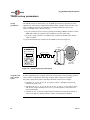
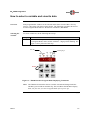
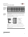
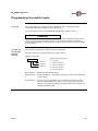
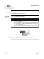
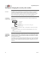
The Analog Output diagnostic puts the TR400 into Pot Output Mode, which permits
you to adjust the 4-20 mA 12-bit isolated, or the 0-10 Vdc output. The same
hardware and procedure are used regardless of the option. There is a direct
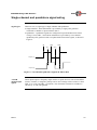
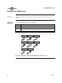
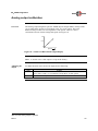
correlation between current/voltage and speed. See Figure 18.
20
mA
4
Sp eed
Figure 18: 420 mA 12 Bit Isolated Output Display
Note: 4-20 mA or 0-10 Vdc output is set up at the factory.
Adjusting the
output
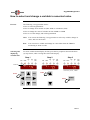
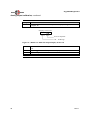
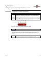
To adjust the 4-20 mA or 0-10 Vdc output, do the following:
Step
1.
2.
Action
Connect a milliammeter with a maximum load resistor of 500 ohms
across TB14 and 5, or a voltmeter if using the 0-10 Vdc option.
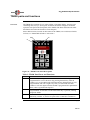
Press the DIAG key.
Continued on next page
The 0-10 Vdc analog output is optional.
Rev D
45