1
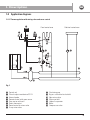
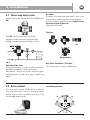
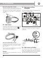
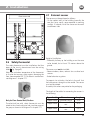
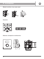
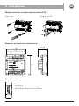
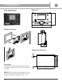
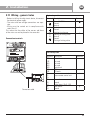
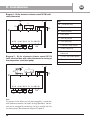
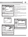
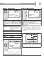
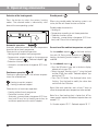
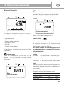
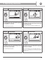
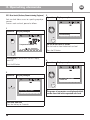
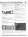
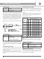
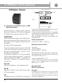
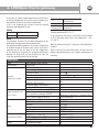
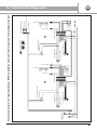
GB
2. Installation
2.1 Three-way mixer valve
Mixture takes place through ways A and B towards
AB.
A
Assembly
Assembly of the valve and servo-motor is easy, since
special tools or travel calibration are not required.
During installation, carefully note the symbol of the
direction of flow of the valve:
Mixing from A/B to AB.
AB
B
Positions
Way AB = total constant flow rate (outlet)
Way A = variable flow rate of the boiler (inlet)
Way B = variable flow rate of the bypass (inlet
OK
OK
OK
Not permitted
Fig. 5
Operation of the valve
To operate the valve, use the standard manual cap
provided or a properly installed servo-control.
Rod upwards: straight way closed, angle way open.
Rod downwards: straight way open, angled way
closed.
2.2 Servo-control
The servo-control (model SSY39) can be assembled
only with mixer valves (see 2.1). The servo-control
and the valve must be assembled muanuality (using
the threaded coupling ring).
Only Floor Controlbox / First Box;
The mixing valve is in preassembled group.
Installation positions
90°
90°
9