1
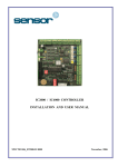
IC1000+JX / IC1000IP+JX CONTROLLER
INSTALLATION AND USER MANUAL
MNCTR1006_IC1000
October, 2006
TABLE OF CONTENTS
1. INTRODUCTION. ......................................................................................................................... 3
2. THE IC1000+ CONTROLLER .................................................................................................... 4
3. FIRMWARE ................................................................................................................................... 5
4. POWER SOURCES AND BOARD CONSUMPTION .............................................................. 5
5. AROUND THE BOARD................................................................................................................ 6
5.1 JUMPERS AND DIPSWITCHES ........................................................................................................ 6
6. TYPES OF CABLE ........................................................................................................................ 7
6.1 CABLE DISTANCES ...................................................................................................................... 8
7. TYPES OF READER AND THEIR CONNECTION ................................................................ 9
7.1 CONNECTING A KEYPAD READER ............................................................................................... 9
7.2 CONNECTING A PROXIMITY READER........................................................................................... 9
8. DOOR CONTACTS AND INPUT DEVICES........................................................................... 10
9. LOCK DEVICE - RELAY OUTPUTS CONNECTION.......................................................... 10
10. PC CONNECTION. ................................................................................................................... 11
10.1 TCP/IP CONNECTION .............................................................................................................. 11
10.2 RS232/RS485 CONNECTION ................................................................................................... 12
10.3 SETTING THE CONTROLLER ADDRESS ..................................................................................... 13
11. USING THE SYSTEM............................................................................................................... 14
11.1 INITIALISATION ........................................................................................................................ 14
11.2 ACCESS .................................................................................................................................... 14
11.3 EVENTS BUFFER ...................................................................................................................... 14
11.4 ALARM INPUTS ........................................................................................................................ 15
11.5 RELAY OUTPUTS...................................................................................................................... 15
12. MULTIPLE CONTROLLERS ................................................................................................. 16
12.1 TCP/IP NETWORK ................................................................................................................... 16
12.2 RS485 NETWORK .................................................................................................................... 16
12.3 MIXED NETWORKS .................................................................................................................. 17
12.4 ADDRESSING MULTIPLE CONTROLLERS .................................................................................. 17
APPENDIX A : 10 IMPORTANT RULES................................................................................... 18
APPENDIX B : TECHNICAL SUPPORT ................................................................................... 19
MNCTR1006_IC1000: IC1000+ Controller Installation and User Manual
2/19
1. INTRODUCTION.
As with all Sensor controllers, the IC1000+JX and the IC1000IP+JX are based on microprocessors which
are designed to operate 24 hours a day. Like all our controllers, the IC1000+ range can be connected to
various external elements such as card readers, electric locks, alarm detection devices, printers, computers,
etc., but the installer should be aware that this kind of system can be subjected to the following problems:
1- Electro Magnetic Interference (EMI). EMI can be present along the cables that connect the controller to the external
elements. Undesired voltage may result in erratic behaviour, random power ups, or even in serious damage.
2- The Exterior Elements themselves.
In cases where readers, door locks, alarms, etc., have not been
supplied/recommended by Sensor, erratic behaviour or complete failure can sometimes result.
Whilst Sensor equipment is manufactured with as much protection as possible from EMI interference, and
despite the fact that Sensor equipment is fully compatible, some installations may be in unsuitable or hostile
environments which can adversely affect the system. In order to minimise this risk, there are a number of
basic rules that should be followed in order to provide maximum protection:
It is absolutely imperative that, from the moment a Sensor controller is installed, the individual responsible
for the installation adheres to the directives listed below. Should any of these directives not be adhered to,
Sensor cannot assume responsibility for any problems that might be encountered.
1. The control unit must never be installed inside a high voltage electrical power box, nor must it be placed
in close proximity to large transformers and/or high voltage/current source devices. Since the controller
may require maintenance, it is also important to consider the accessibility of the unit.
2. The IC1000+ boards must be separately grounded, so it is important to ascertain whether the installation
site can provide adequate grounding facilities.
3. It is essential to plug the mains power cable into a clean line (i.e. a line not being used by other pieces of
equipment), or into an independent line which has been specifically allocated to the controller.
4. The cover or case that contains the controller should be tightly screwed down or locked in place.
5. Never use the system cables guide to pass wires from another system, such as using a conduit also used by
other cables.
6. Generally speaking, there are five categories of cable that can go to or from the controller, as listed in
section 5. These cables must be installed as far as possible one from the other, and should always be of the
types recommended, or their equivalents.
MNCTR1006_IC1000: IC1000+ Controller Installation and User Manual
3/19
2. THE IC1000+ CONTROLLER
MNCTR1006_IC1000: IC1000+ Controller Installation and User Manual
4/19
3. FIRMWARE
Both the IC1000+JX and IC1000IP+JX boards have open (changeable) flash firmware installed on their
ROM chip in the upper-right of the board. This firmware has been pre-configured to allow up to 10,000
individual users to be stored in the board’s memory, and is further controlled by Sensor’s access control
software, GuardPoint Pro and GuardPoint Pro Lite.
4. POWER SOURCES AND BOARD CONSUMPTION
The board is powered by a 12vDC current. With no external devices (readers, locks, alarms, etc.) attached,
the board’s consumption is 120mA maximum (IC1000+JX), or 370mA maximum (IC1000IP+JX).
The maximum consumption allowed through the 5V terminals on terminal blocks J1 and J2 is 150 mA.
When supplied in a metallic housing, Sensor’s Power Supply Unit (PSU) board is also usually present. With
this supply, you are given five independent outputs:
- 2 x green 12V/1.5A terminals
- 2 x green 12V/2A terminals
- 1 x blue 12V terminal
- for powering the card/fob readers
- for powering the electric door locks
- for powering the controller
Two LEDs indicate the status of the mains power input and the 12V/1.5A outputs.
An output, Power Failure, indicates the mains power status, and may also be directly connected to an alarm
input in order to raise an alert if the main power should fail.
In addition to the mains power cable, the PSU is also capable to drawing from a 12vDC 6A/H Lead-Acid
Rechargeable battery. With such a battery, the autonomy of the system is as follows:
- IC1000+ with 2 readers:
30 hours
- IC1000+ with 2 readers at 100 door openings/hour: 22 hours (assuming a 4 sec. opening of a 12V/0.5A electric lock)
In the case of power failure, these two outputs are connected together so that the battery powers both the
IC1000+, and the electric locks. A jumper may be disabled to prevent this feature and force the battery to
power only the IC1000+.
Important!
- Whilst most card readers can be connected to the 5V terminal on the IC1000+, we strongly advise that all
readers, regardless of their type, are powered directly from the 12V/1.5A terminals on the PSU.
MNCTR1006_IC1000: IC1000+ Controller Installation and User Manual
5/19
5. AROUND THE BOARD
Both the IC1000+JX and IC1000IP+JX use the same circuit board, with just the presence/absence of the
TCP/IP module being the only difference. The basic layout of the board can be seen below:
Terminal Blocks
J1
Reader 1
J2
Reader 2
J3
RS485/RS232 connection
J4
Relay 1 - 3 connection
J5
Input 1 - 4 connection
J6
Power (12vDC)
Jumpers
JP1
Maintains power to board
JP2
Selects RS485 or RS232
JP3
Board reset jumper
Dipswitches
DS1
Address, see Section 10.3
5.1 Jumpers & Dipswitches
Both the IC1000+JX and the IC1000IP+JX have three sets of jumpers and one set of dipswitches, all of
which are important for the smooth function of the board.
Jumpers
JP1 – Battery Jumper
Located:
Middle-left of the board, to the top-left of the Lithium-Ion battery
Function:
Maintains the power to the battery. The board will not work without this jumper
Default:
On (shorted)
JP2 – Communication Jumpers
Located:
Bottom-middle of the board, just above the communication terminal, J3
Function:
To swap between RS232 and RS485 communication protocol
Default:
As required, see Section 10.2
JP3 – Reset Jumper
Located:
Top-left of the board, to the right of the TCP/IP module area
Function:
Resets the board when shorted and clears the memory of the flash ROM
Default:
Off (not shorted)
Dipswitches
DS1 – Red 8 Switch Bank
Located:
Middle-right of the board
Function:
Sets both the controller address and the data type of the connected readers.
Switches 1 to 5 control the address settings.
Switch 6 on, switches 7 & 8 off sets the data type to Wiegand (with parity)
Switch 7 on, switches 6 & 8 off sets the data type to Wiegand (without parity)
Switch 8 on, switches 6 & 7 off sets the data type to Pac Easykey
Switches 6 & 7 on, switch 8 off sets the data type to Touch
Switches 6 & 8 on, switch 7 off sets the data type to Radio
Switches 7 & 8 on, switch 6 off sets the data type to Watermark
Switches 6, 7 & 8 on sets the data type to Mag ISO1 or Barcode 2/5
Default:
Switches 1 to 5 as required, see Section 10.3
Switch 6 on, switches 7 & 8 off
MNCTR1006_IC1000: IC1000+ Controller Installation and User Manual
6/19
6. TYPES OF CABLE
Any standard installation will have five basic categories of cable:
1) The Mains Power Cable
This will generally be the cable that connects the PSU (Power Supply Unit) to the mains power.
•
Sensor recommend a 3 lead cable, with one marked as Earth according to the standards applied in
each country
2) The Cables that Connect the Readers
Each reader comes complete with a length of cable attached. However, there may be times when you want
to extend this cable further. In these situations, it is important to select the correct type.
•
Sensor recommend Belden 9421 for Proximity/Keypad readers and Belden 8458 for Biometric
readers
3) The Cables that Connect the Alarms, Buttons, etc.
These cables will be any which connect your Request To Exit (RTX) buttons, alarms, or other external
devices to the controller. Generally speaking, these cables should be as short as possible.
•
Sensor recommend any 22AWG, 2 conductor cable
4) The Communication Cable(s)
These will fall into one of three types, depending on your network configuration; TCP/IP, RS232 or RS485.
•
Sensor recommend Belden 1624P for TCP/IP, Belden 8443 for RS232 and Belden 9841 (a shielded,
twisted pair cable) for RS485
5) The Cables that Connect the Locks or other External Release Devices
These cables will be any which connect your electric locks or other release devices to the controller. Like
any cable, these should ideally be as short as possible.
•
Sensor recommend any 18AWG, 2 conductor cable
Although Sensor recommend Belden cable, you can use an equivalent cable type. In order to provide you
with a basis of comparison, here are those cable types in greater detail:
Cable Use:
Recommended:
Gauge:
Shielded:
Twisted:
No. Conductors:
No. Pairs:
Stranding:
Resistance:
Proximity / Keypad
Belden 9421
22AWG
No
No
8
0
7x30
10Ω/100m @ 200C
Biometric
Belden 8458
22AWG
No
No
15
0
7x30
10Ω/100m @ 200C
RS232
Belden 8443
22AWG
No
No
3
0
7x30
10Ω/100m @ 200C
MNCTR1006_IC1000: IC1000+ Controller Installation and User Manual
RS485
Belden 9841
24AWG
Yes
Yes
2
1
7x32
16Ω/100m @ 200C
TCP/IP
Belden 1624P
24AWG
Yes
Yes
8
4
Solid
16Ω/100m @ 200C
7/19
6.1 Cable Distances
As important as cable type is the question of cable distance, particularly if the installation is an unusually
large one. As a general rule, the longer the cable, the greater the potential for problems.
Cable Type
Recommended Cable
Max Length
TCP/IP
24AWG, Shielded, 4 pairs
100m / 328ft
RS232
22AWG, Unshielded, 3 wire
30m / 98ft
RS485
24AWG, Shielded, 2 wire
See Notes (1)
Keypad
22AWG, Unshielded, 8 wire
100m / 328ft
Bio-Unit
22AWG, Unshielded, 15 wire
100m / 328ft
Proximity
22AWG, Unshielded, 8 wire
100m / 328ft
Power (Readers)
22AWG, Unshielded, 2 wire
20m / 65ft
Lock
18AWG, Unshielded, 2 wire
10m / 32ft
Alarm
22AWG, Unshielded, 2 wire
If greater than 10m, use a shield
Notes:
1)
For an RS485 connection, the maximum distance of the cable is 1200m (3937ft).
The shield of each section must be connected to the next to maintain shield
continuity, and then earthed at one end (usually at the RS232/RS485 earth).
If the total distance of the RS485 cable exceeds a certain distance (see table
below), then a 120Ω resistor should be fitted at the far end (i.e. at the last
controller).
Baud Rate
4800
9600
19200
38400
Max. Distance Without Resistor
600m (1968ft)
300m (984ft)
150m (492ft)
80m (262ft)
2)
At least 50cm must separate all connecting cables from high-tension cables,
cables connected to an electrical power box controlled by the system, or from any
cables capable of generating strong interference (such as cables connected to
high-power motors, generators, wireless telephone, etc.). Since it is often located
besides a variety of cables, the external telephone line can also be a source of
interference. IMPORTANT! Do not put reader cables in the same conduit as lock
and/or communication cables.
3)
The maximum distance of TCP/IP cables depends on the LAN specifications of the
installation site. Consult the system administrator if you require assistance.
MNCTR1006_IC1000: IC1000+ Controller Installation and User Manual
8/19
7. TYPES OF READER AND THEIR CONNECTION
The IC1000+ controllers can recognise almost any kind of reader technology, and – with the use of switches
6, 7 and 8 on the dipswitch bank DS1 – can be set to interact with them effectively, however, for the vast
majority of installations dipswitch 6 should be set to ON and switches 7 & 8 set to OFF.
Since the vast majority of installations will involve products from either our keypad range or our proximity
reader range, details for wiring them are reproduced here. If you intend to use different technologies, please
refer to the relevant manual, or contact Sensor’s technical support department on +44 (0) 870 890 1154.
7.1 Connecting a Keypad Reader
Sensor Available Models :
SP-KPV
KPV
To Extend Cable Use:
Belden 9421 (22AWG, non-twisted, 8 conductor). Maximum length: 100m.
Notes:
Must be programmed prior to use. To program either model, press the hash (#) key four times,
then enter the security code (1 2 3 4 by default). Press the digit 1 to select the programming
type, then press the digit 3 to select the programming option. The unit is now ready for use.
WIRE
PSU BOARD
RED (+V)
BLACK (0V)
GREEN (Data-0)
WHITE (Data-1)
BROWN (LED Control)
PURPLE (Tamper)
12vDC 1.5A
0vDC 1.5A
IC1000+JX / IC1000IP+JX CONTROLLER
CK1 / CK2
DT1 / DT2
LD1 / LD4
If required, connect to a spare input on controller
7.2 Connecting a Proximity Reader
Sensor Available Models :
SP-MINI
SP-SG
SP-VRS
To Extend Cable Use:
Belden 9421 (22AWG, non-twisted, 8 conductor). Maximum length: 100m.
Notes:
Some models of the SP-VRS and some older models of the SP-MINI also have Orange and Yellow
wires. For these, the Orange cable should be wired to the first LED terminal (LD1 / LD4), the
Brown to the second (LD2 / LD5) and the Yellow to the buzzer (BZ1 / BZ2).
WIRE
PSU BOARD
IC1000+JX / IC1000IP+JX CONTROLLER
RED (+V)
BLACK (0V)
GREEN (Data-0)
WHITE (Data-1)
BROWN (LED Control)
PURPLE (Tamper)
12vDC 1.5A
0vDC 1.5A
5v
0v
CK1 / CK2
DT1 / DT2
LD1 / LD4
If required, connect to a spare input on controller
MNCTR1006_IC1000: IC1000+ Controller Installation and User Manual
9/19
8. DOOR CONTACTS AND INPUT DEVICES
A magnetic contact, passive infra-red unit, request to exit switch or any other form of contact can be
connected to and monitored via the IC1000+ system. There are four standard inputs on each controller, and
all can be set up from the GuardPoint Pro / GuardPoint Pro Lite software to trigger certain tasks, such as
opening doors, setting alarms, or simply informing your security staff.
As standard, inputs I3 and I4 are configured to allow connection of Request to Exit (REX) switches for door
1 and door 2 respectively, although this configuration can be altered - or removed entirely - via the access
control software to suit your requirements.
Protection Against RFI Interference:
The following should be considered in order to prevent malfunction or interruption:
1.
2.
If the distance between the alarm detector, push-button, etc., and the controller board is greater than 10 meters, use a
shielded cable and connect the shields to the ground of the control unit.
Always ensure that a distance of at least 50 cm separates the connecting cables from both high-tension cables and
electric lock cables.
9. LOCK DEVICE - RELAY OUTPUTS CONNECTION
The three relays on the controller can support a maximum of 24V/1A, and each is completely configurable
via the GuardPoint Pro / GuardPoint Pro Lite software.
The standard wiring configuration of an electronic lock can be seen below:
In this example, an electronic lock is wired to Relay 1.
As shown, it is always important to fit a diode at the
lock end of the output, of type 1N4004 or equivalent.
It is also important to wire the positive and negative
directly to the appropriate terminals on the separate
Power Supply Unit (PSU).
Important!
- If the release mechanism has a charge that exceeds the authorised limit or has a strong inductive charge (as
in the case, for example, of revolving doors or turnstiles), then it will be necessary to use an intermediate
relay between the system and the charge. The charge must be powered with a separate power supply. The
intermediate relay and the IC1000+ boards may both be powered with the same power supply.
- The cable connecting the release mechanism to the controller (or to the intermediate relay) must be
isolated, and there must be a distance of at least 50cm between this cable and the other cables.
MNCTR1006_IC1000: IC1000+ Controller Installation and User Manual
10/19
10. PC CONNECTION
10.1 TCP/IP Connection
The IC1000IP+JX controller is supplied with a TCP/IP socket on board, allowing it to be assigned an IP
address and so added to a TCP/IP network. If you are using the IC1000+JX (the non-TCP/IP version), you
can disregard this section and move on to 8.2 or 8.3, depending upon your method of communication.
In order to connect the IC1000IP+JX, plug one end of a standard RJ45 network cable into the socket, and the
other either into your router/hub, or directly into the Ethernet socket on a PC; the controller will then appear
on the network. Before it can be used, however, the controller must be configured via the application DS
Manager (available on the GuardPoint Pro disc, or for free download from the Sensor website).
To configure the controller, please go to
Start, Programs, Tibbo, DS Manager. A
window such as that on the right will now
appear.
In the main panel of the window will be a list
of all currently detected TCP/IP controllers.
It is almost certainly the case that your
IC1000IP+JX is new, and so has a default IP
address. This, along with some other settings,
will need to be changed.
Click on the visible TCP/IP controller to
select it, then click on the Settings button at
the top of the window to bring up the
configuration window.
There are a series of tabs running across the top of the window. Using the tabs you will need to locate the
following settings and change them:
IP-address
Port
Transport Protocol
RTS/CTS flow control
DTR mode
Baud rate
This should be a unique address
This should be set to ‘1001’
This should be set to ‘1-TCP’
This should be ‘0-Disabled or remote’
This should be ‘0-Idle or remote’
This should be set to ‘3-9600 bps’
Once changed, click Ok to return to the main window. The IC1000IP+JX is now configured and its status
icon – represented by the blue plug to the left - should be solid and clear (as in the screenshot).
The controller is now ready to communicate with the software. For full details on establishing
communication, please refer to the GuardPoint Pro / Pro Lite manual.
Important!
- When assigning an IP address, it is vital that you choose one that will be compatible with your existing
network/PC. In most cases, this will mean using the first, second and third sets of digits from your
PC/router, and making the last set unique. For example, an IC1000IP+JX controller is plugged into a router
that has an IP address of 192.168.1.10. The controller’s IP address should therefore 192.168.1.XXX, where
XXX is any unique number (in the above screenshot, 19).
It is vital that IP addresses do not share the same numbers. For further assistance, please consult whoever
manages the PC network at the installation site, or contact Sensor’s technical support department.
- If you are intending to use Biometric readers, the baud rate should be set to ‘5-38400 bps’.
MNCTR1006_IC1000: IC1000+ Controller Installation and User Manual
11/19
10.2 RS232/RS485 Connection
Whilst the IC1000IP+JX has an RJ45 network connection socket on board, both the IC1000IP+JX and the
IC1000+JX can be connected to a PC via the RS232/RS485 port.
If the controller has to be connected to a PC at less than 30 meters, either the RS232 port or the RS485 port
may be used. If the distance is greater than 30 meters, or if several controllers must be connected together,
the RS485 port should be used.
The default characteristics of the serial transmission are: Asynchronous Serial Transmission, 9600 baudrate,
8 data bits, no parity, 2 stop bits. Note that the baud rate may be changed from the PC software.
RS232 Port. Jumpers JP2
:::
The three signals - 0v, Rx and Tx - are connected to a serial plug in the PC as follows:
25 Pin Plug (PC)
Pin 7 (0v)
Pin 2 (Transmit)
Pin 3 (Receive)
RS485 Port. Jumpers JP2
9 Pin Plug (PC)
Pin 5 (0v)
Pin 3 (Transmit)
Pin 2 (Receive)
IC1000+ J3
0v
Rx/L
Tx/H
:::
In nearly all cases RS485 connection will take place via an RS485/USB interface, however in the rare
situations where an RS485/RS232 interface is to be used, the interface should be wired to the PC according
to the details above.
To connect via an RS485/USB interface, simply plug the USB connector into a port, and wire as follows:
USB485
XX+
IC1000+ J3
Rx/L
Tx/H
The GuardPoint Pro / GuardPoint Pro Lite software can then be configured to communicate with the
controller via the RS485/USB interface. Fuller details and instructions on this connection can be found on
the datasheet supplied with the interface, or from the Sensor website.
Protection Against RFI Interference:
Most of the interference will come via induction to the cable shield, on which high and very high voltages
may appear. To prevent this, the following rules should be considered:
1.
2.
3.
4.
5.
Use a Belden 8443 triple-wire cable ("Receive"/"Transmit"/0v) for the RS232 connection, and a Belden 9841
twisted and shielded pair cable for the RS485 connection.
A good quality cable shield must be used and the shield must be connected to a strong earth. The shield should be
copper rather than aluminium, since the latter provides only partial attenuation.
All communication cable shielding should be connected to only one extremity in order to avoid the problem of
ground loops, whereas the connection for the RS485 wire shield should be carried out at the level of the
concentrator, and the connection for the RS232 wire shield should be carried out at the level of the terminal.
A distance of at least 50cm must separate all connecting cables from high-tension cables, from cables connected to
an electrical power box controlled by the system, or from any cables capable of generating strong interference (such
as cables connected to high-power motors, generators, wireless telephone, etc.). Since it is often located besides a
variety of cables, the external telephone line can also be a source of strong interference.
Extremely high tension produced by lightning bolts can enter the terminals through these lines. Such tension can
reach the level of hundreds of thousands of volts, so it is advisable to use some form of surge protection.
Important!
- Do not connect the communication cable screen at any point other than at the RS232/RS485 interface end.
- For all TCP/IP connections, Belden 1624P (24AWG, CAT5, shielded ethernet) cable is recommended.
- For all RS232 connections, Belden 8443 (22AWG, non-twisted) cable is recommended.
- For all RS485 connections, Belden 9841 (24AWG, twisted and shielded pair) cable is recommended.
MNCTR1006_IC1000: IC1000+ Controller Installation and User Manual
12/19
10.3 Setting the Controller Address
In order to programme the system, each controller has to have a unique address. This address is defined
with the switches 1 to 5 on the dipswitch bank DS1. Please consult the table below when setting the
address. In this table 0 = OFF (switch is to the Left) and 1 = ON (switch is to the Right):
Switch
12345
00000
10000
01000
11000
00100
10100
01100
11100
00010
10010
01010
11010
00110
10110
01110
11110
Address
00
01
02
03
04
05
06
07
08
09
10
11
12
13
14
15
Switch
12345
00001
10001
01001
11001
00101
10101
01101
11101
00011
10011
01011
11011
00111
10111
01111
11111
Address
16
17
18
19
20
21
22
23
24
25
26
27
28
29
30
31
Addressing the IC1000+ Controller
MNCTR1006_IC1000: IC1000+ Controller Installation and User Manual
13/19
11. USING THE SYSTEM
11.1 Initialisation
Before using the system, it must be initialised and programmed from the host computer. You will need to
refer to the GuardPoint Pro / GuardPoint Pro Lite manual for details, or call our technical support
department who will be happy to walk you through the process.
11.2 Access
To request access, either pass a card and/or key in a PIN code at the keypad unit.
In situations where a keypad is being used, a keyed code must be followed with the hash (#) key in order to
be validated or by the star (*) key to be cancelled. In the case of an SP-KPV, where both a card and PIN
may be required, the PIN must be keyed after the card is presented.
If you have a magnetic reader the card track must be located on the right-hand side; if you have a barcode
reader the code must be located on the left-hand side; for other technologies refer to the instructions supplied
with the product.
The controller then checks the request according to its internal databases:
-If access is granted, the reader’s green led will light and the door will unlock.
-If access is denied, the reader’s red led will light and the door will remain locked.
Successful access relies upon the card/code having been set up previously in the GuardPoint Pro /
GuardPoint Pro Lite software. Complete directions on how to enrol badges can be found in the manual that
is supplied with the software.
11.3 Events Buffer
All events (card transactions and alarms) are recorded in the Events Buffer on the controller’s internal
memory. In both the IC1000+JX and IC1000IP+JX, this buffer can hold up to 4000 events.
When the Buffer is almost full (at approx. 3880 events in memory), each subsequent card transaction will
result in the system sounding with 2 short bleeps and the LED blinking 3 times. These warning messages
are your indication to clear the buffer from the software, and, upon being cleared, the warning will
disappear.
When the Buffer is full, the system will behave in one of two ways:
1.
2.
If the 'Access Granted when Buffer Full' option has been set in GuardPoint Pro / GuardPoint Pro Lite, the system
will start to record the new transactions over the existing ones, so the warning will disappear.
If the ‘No Access if Buffer is Full’ option is set, the system will issue an audible and visual warning at each card
pass, as described above. Access will not be granted, even for valid cardholders, and no new transactions will be
recorded in the buffer. The system can only be unlocked by connecting the controller to a PC and downloading the
events.
MNCTR1006_IC1000: IC1000+ Controller Installation and User Manual
14/19
11.4 Alarm Inputs
The IC1000+ controllers have a total of 4 inputs, to which any kind of detector may be connected (magnetic
contacts, passive infra-red, request to exit, etc.). The mode of each input (Normally Open or Normally
Closed), together with its time zone, is fully programmable from the access control software, and may be set
up to operate in the following modes:
1.
2.
Door Control for a Door Alarm
If a door contact is connected to the 'Door control' input, an alarm will be raised on the 2 following cases:
a. The door is forced opened, i.e. opened with no valid card.
b. The door is opened with a valid card but left opened more than a pre-defined delay.
Door Remote Button (Request to Exit, RTX)
The door may be opened via a push button connected to the 'Door Remote' input. By default, this will be I3 for door
1 and I4 for door 2, although it is fully configurable from the GuardPoint Pro / GuardPoint Pro Lite software.
In both the IC1000+JX and the IC1000IP+JX, an alarm message is also sent to the PC, which may in turn be
configured to take certain actions.
11.5 Relay Outputs
The IC1000+ controllers have 3 output relays. The function of each relay, and the way in which it is
activated, is fully programmable through the GuardPoint Pro / GuardPoint Pro Lite software.
MNCTR1006_IC1000: IC1000+ Controller Installation and User Manual
15/19
12. MULTIPLE CONTROLLERS
As well as connecting to a single controller, it is also possible to link several controllers togther, either in a
single network or in multiple networks. Depending on your installation, and the types of controller
involved, there are various methods of achieving this, so what follows is a very general guide.
If what you require isn’t covered in this guide, or you require further clarification on a particular point,
please do not hesitate to contact our technical support department, who will be happy to assist you.
Generally speaking, multiple controllers will fall into one of two types; an RS485 network, or a TCP/IP
network. It is also possible to mix these two types of network to a degree, with the computer connecting to a
controller via TCP/IP, and that controller then connecting to another via an RS485 cable.
12.1 TCP/IP Network
An all-TCP/IP network is perhaps the easiest to establish. Each controller has an RJ45 socket, either
embedded in the board (as in the case of an IC1000+IP), or as part of an extension board (as in an expanded
IC2000 or IC4000), and each of these is connected to a router or hub.
Requires:
Setup:
Advatange(s):
infinite.
Disadvantage(s):
1) A router/hub with enough ports for each controller and the PC running GuardPoint Pro.
2) Each controller requires it’s own TCP/IP RJ45 socket.
Hardware
Each controller and the computer running GuardPoint Pro is connected to the router/hub via an ethernet
cable. It is important to get the correct type of cable, which will normally be of the patch lead type.
Each controller must be configured with the DS Manager software (see section 10.1).
Software
In GuardPoint Pro, each controller needs a separate network. This is established in the Parameter,
Controller Network window, as detailed in the GuardPoint manual.
1) Since the network runs on TCP/IP, the overall distances that can be covered are theoretically
2) TCP/IP is an extremely stable, very reliable method of connection.
3) Using standard computing tools and methods, a TCP/IP network is very easy to troubleshoot / test.
In a purely TCP/IP environment, you can only have 1 controller per network in the software.
12.2 RS485 Network
An all-RS485 network is still the most common type of network. Each controller has a terminal block that
consists of a Transmit terminal and a Receive terminal, into which is wired the RS485 cable. Up to 32
individual controllers can share the same RS485 network, with each controller connected to the next.
Requires:
Setup:
Advatange(s):
Disadvantage(s):
1) An RS485 converter that allows for connection between the computer and the first controller. This
is normally via a USB485 device.
2) Suitable cable for the RS485 bus that will connect each controller (see section 6).
Hardware
The PC is connected to the first controller, usually by a USB485 converter, which wires directly to the
Tx/H and Rx/L terminals.
Each controller has its Tx/H and Rx/L terminals wired to the Tx/H and Rx/L terminals of the next
controller (so controller 1 is wired to controller 2, controller 2 to controller 3, and so on).
A network exceeding a certain distance may require a resistor (see the table in section 6.1).
Software
In GuardPoint Pro, you need to establish only one network. This is established in the Parameter,
Controller Network window, as detailed in the GuardPoint Pro manual.
Each controller is then setup in the Parameter, Controller window, as per the GuardPoint Pro manual.
1) A single network can have up to 32 individual controllers, of varying type.
2) With proper grounding, an excellent level of RFI immunity can be gained.
1) An RS485 network cable can only maintain reliable communication up to a total distance of 1200m.
2) The RS485 cable can be susceptible to RFI interference (see section 10.2).
MNCTR1006_IC1000: IC1000+ Controller Installation and User Manual
16/19
12.3 Mixed Networks
In addition to ‘pure’ networks (that is, networks that are either exclusively TCP/IP or exclusively RS485), it
is also possible to mix the two connection types.
Generally speaking, because a TCP/IP connection requires its own network in the software, any mixed
network must begin by being connected directly to the TCP/IP controller, with the subsequent RS485
controllers being added to it, one after the other.
In the case of an IC1000+IP being the controller that begins the network, then RS485 cables to the next
controller will run from from the Tx/H and Rx/L terminals in block J3 as standard, with each subsequent
controller being added as per the RS485 network instructions outlined in section 12.2 above.
However, if an IC2000 or IC4000 begins such a network, then the RS485 connection between it and the next
controller must originate from the H and L terminals on the TCP/IP extension board, and not the Tx/H and
Rx/L terminals of the main board. The reason for this is that by adding a TCP/IP extension board, the
RS485 terminal block of the IC2000/IC4000 (J4) becomes deactivated.
Subsequent controllers are added as per the RS485 network instructions outlined in section 12.2 above.
In mixed networks where more than one TCP/IP connected controller is present, each one will need to form
the first controller of its own network.
For example, if you have two controllers that are connected to a network via TCP/IP, an IC1000+IP and an
IC2000 with a TCP/IP extension board, then you will establish two networks in the GuardPoint Pro
software.
By adding extra controllers to their of these two via an RS485 conenction, each of these two networks can
contain up to 32 controllers in total, allowing for dozens of inputs and relays to be utilised.
12.4 Addressing Multiple Controllers
In any installation where you have multiple controllers on the same network, they must be correctly – and
individually - addressed. Addressing is configured via the red bank of dipswitches, and further details on the
dwitch settings can be found under section 10.3.
In most cases, the first controller in any network will be address 00, the second 01, the third 02, and so on.
Whilst it is not essential to follow a sequential progression, it is logical, and will make locating certain
controllers much easier at a later date, especially if problems have to be troubleshooted.
Important!
- Each controller must have a unique address (i.e. one not shared by any other controller in that network).
- Controllers in different networks can have the same address. For example, there can be an address 17
controller in network 1, and an address 17 controller in network two.
MNCTR1006_IC1000: IC1000+ Controller Installation and User Manual
17/19
APPENDIX A : 10 IMPORTANT RULES
DC +
Separate
Power
S
l
10 cm.
1. Never pass the door opener cable near the other
cables; it must be at least 10cm from all other cables.
-
2. Use always a diode if the electric lock is DC
powered. The diode should be installed at the lock
end, and should be a 1N4004 type or equivalent.
12Vdc
Co
No
-
RS232/RS485
0V.
Controller
RS485
Lo
Interface
3. If the electric door lock consumption is more than
24V/1A, use an intermediate relay.
No Relay
Common
+
4. If the total distance between the controller and
RS485 Interface is greater than 500m, install a 120
ohms resistor at the end of the RS485 line.
Hi
Last
Controller
RS485
Lo
5. Never connect a controller to the RS485 bus farther
than 3 meters.
Max. 3
Hi
Controller
RS232/RS485
Interface
Gnd
RS485 Bus
Lo
Lo
Hi
Controller
Controller
Controller
Power
Supply
6. Link all the RS485 wire shields together and
connect them at the RS232/RS485 Interface
end, never the controller end.
Controller
Hi
7. Use a good earth at the Interface.
8. Use surge protection if the region is
susceptible to lightning.
9. Never install a controller - or its cables - near high
voltage lines or a heavy duty electric devices (such as
motors, transformers, high voltage sources, etc.).
10. Never use the same single power supply for both
the controller and the electric lock. Use either separate
supplies, or the PSU (Power Supply Unit) board in the
controller case.
MNCTR1006_IC1000: IC1000+ Controller Installation and User Manual
18/19
APPENDIX B : TECHNICAL SUPPORT
In the unlikely event that you encounter problems with your installation/running of the site, it may be
necessary to contact our technical support department. Support is available from 08:30 to 17:30, Monday to
Friday, and we are happy to answer your questions, or to guide you through any aspect of your installation.
Sensor Access Technology Ltd
Technical Support Team
Sensor House
Westergate Road
Brighton
BN2 4JZ
[email protected]
+44 (0) 870 890 1154
Manuals, Installation Guides, Datasheets and
Application Notes are available from our website:
http://www.sensoraccess.co.uk
MNCTR1006_IC1000: IC1000+ Controller Installation and User Manual
19/19