1
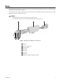
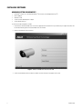
INSTALLATION/OPERATION
TI2500 Series
Fixed-Mount
Thermal Imager
TI2535 and TI2550 Models
C1309M-A (9/08)
Contents
Important Safety Instructions . . . . . . . . . . . . . . . . . . . . . . . . . . . . . . . . . . . . . . . . . . . . . . . . . . . . . . . . . . . . . . . . . . . . . . . . . . . . . . . . . . . . . . . . . . . . 4
Regulatory Notices . . . . . . . . . . . . . . . . . . . . . . . . . . . . . . . . . . . . . . . . . . . . . . . . . . . . . . . . . . . . . . . . . . . . . . . . . . . . . . . . . . . . . . . . . . . . . . . . . . . . 5
Description. . . . . . . . . . . . . . . . . . . . . . . . . . . . . . . . . . . . . . . . . . . . . . . . . . . . . . . . . . . . . . . . . . . . . . . . . . . . . . . . . . . . . . . . . . . . . . . . . . . . . . . . . . . 6
Models . . . . . . . . . . . . . . . . . . . . . . . . . . . . . . . . . . . . . . . . . . . . . . . . . . . . . . . . . . . . . . . . . . . . . . . . . . . . . . . . . . . . . . . . . . . . . . . . . . . . . . . . . 6
Parts List . . . . . . . . . . . . . . . . . . . . . . . . . . . . . . . . . . . . . . . . . . . . . . . . . . . . . . . . . . . . . . . . . . . . . . . . . . . . . . . . . . . . . . . . . . . . . . . . . . . . . . . . 6
Setup . . . . . . . . . . . . . . . . . . . . . . . . . . . . . . . . . . . . . . . . . . . . . . . . . . . . . . . . . . . . . . . . . . . . . . . . . . . . . . . . . . . . . . . . . . . . . . . . . . . . . . . . . . . . . . . 7
Installing Software . . . . . . . . . . . . . . . . . . . . . . . . . . . . . . . . . . . . . . . . . . . . . . . . . . . . . . . . . . . . . . . . . . . . . . . . . . . . . . . . . . . . . . . . . . . . . . . . 8
Minimum System Requirements . . . . . . . . . . . . . . . . . . . . . . . . . . . . . . . . . . . . . . . . . . . . . . . . . . . . . . . . . . . . . . . . . . . . . . . . . . . . . . . . . 8
Bench Setup . . . . . . . . . . . . . . . . . . . . . . . . . . . . . . . . . . . . . . . . . . . . . . . . . . . . . . . . . . . . . . . . . . . . . . . . . . . . . . . . . . . . . . . . . . . . . . . . . . . . . 9
Disassemble the Enclosure . . . . . . . . . . . . . . . . . . . . . . . . . . . . . . . . . . . . . . . . . . . . . . . . . . . . . . . . . . . . . . . . . . . . . . . . . . . . . . . . . . . . . 9
Connect Wiring . . . . . . . . . . . . . . . . . . . . . . . . . . . . . . . . . . . . . . . . . . . . . . . . . . . . . . . . . . . . . . . . . . . . . . . . . . . . . . . . . . . . . . . . . . . . . 10
Interfacing with a PC . . . . . . . . . . . . . . . . . . . . . . . . . . . . . . . . . . . . . . . . . . . . . . . . . . . . . . . . . . . . . . . . . . . . . . . . . . . . . . . . . . . . . . . . . 12
Reassemble the Enclosure. . . . . . . . . . . . . . . . . . . . . . . . . . . . . . . . . . . . . . . . . . . . . . . . . . . . . . . . . . . . . . . . . . . . . . . . . . . . . . . . . . . . . 12
Field Setup . . . . . . . . . . . . . . . . . . . . . . . . . . . . . . . . . . . . . . . . . . . . . . . . . . . . . . . . . . . . . . . . . . . . . . . . . . . . . . . . . . . . . . . . . . . . . . . . . . . . . 13
Disassemble the Enclosure . . . . . . . . . . . . . . . . . . . . . . . . . . . . . . . . . . . . . . . . . . . . . . . . . . . . . . . . . . . . . . . . . . . . . . . . . . . . . . . . . . . . 13
Connect Wiring . . . . . . . . . . . . . . . . . . . . . . . . . . . . . . . . . . . . . . . . . . . . . . . . . . . . . . . . . . . . . . . . . . . . . . . . . . . . . . . . . . . . . . . . . . . . . 13
Reassemble the Enclosure. . . . . . . . . . . . . . . . . . . . . . . . . . . . . . . . . . . . . . . . . . . . . . . . . . . . . . . . . . . . . . . . . . . . . . . . . . . . . . . . . . . . . 14
Configuration . . . . . . . . . . . . . . . . . . . . . . . . . . . . . . . . . . . . . . . . . . . . . . . . . . . . . . . . . . . . . . . . . . . . . . . . . . . . . . . . . . . . . . . . . . . . . . . . . . . . . . . . 15
Camera Tab. . . . . . . . . . . . . . . . . . . . . . . . . . . . . . . . . . . . . . . . . . . . . . . . . . . . . . . . . . . . . . . . . . . . . . . . . . . . . . . . . . . . . . . . . . . . . . . . . . . . . 15
Save Settings. . . . . . . . . . . . . . . . . . . . . . . . . . . . . . . . . . . . . . . . . . . . . . . . . . . . . . . . . . . . . . . . . . . . . . . . . . . . . . . . . . . . . . . . . . . . . . . 15
Factory Defaults. . . . . . . . . . . . . . . . . . . . . . . . . . . . . . . . . . . . . . . . . . . . . . . . . . . . . . . . . . . . . . . . . . . . . . . . . . . . . . . . . . . . . . . . . . . . . 15
Reset . . . . . . . . . . . . . . . . . . . . . . . . . . . . . . . . . . . . . . . . . . . . . . . . . . . . . . . . . . . . . . . . . . . . . . . . . . . . . . . . . . . . . . . . . . . . . . . . . . . . . 15
Flat Field Correction. . . . . . . . . . . . . . . . . . . . . . . . . . . . . . . . . . . . . . . . . . . . . . . . . . . . . . . . . . . . . . . . . . . . . . . . . . . . . . . . . . . . . . . . . . 15
Status. . . . . . . . . . . . . . . . . . . . . . . . . . . . . . . . . . . . . . . . . . . . . . . . . . . . . . . . . . . . . . . . . . . . . . . . . . . . . . . . . . . . . . . . . . . . . . . . . . . . . 16
Video Tab . . . . . . . . . . . . . . . . . . . . . . . . . . . . . . . . . . . . . . . . . . . . . . . . . . . . . . . . . . . . . . . . . . . . . . . . . . . . . . . . . . . . . . . . . . . . . . . . . . . . . . 17
Changing the Image Orientation Mode . . . . . . . . . . . . . . . . . . . . . . . . . . . . . . . . . . . . . . . . . . . . . . . . . . . . . . . . . . . . . . . . . . . . . . . . . . . 17
Changing the Polarity/LUT Setting . . . . . . . . . . . . . . . . . . . . . . . . . . . . . . . . . . . . . . . . . . . . . . . . . . . . . . . . . . . . . . . . . . . . . . . . . . . . . . 18
Pan and Zoom . . . . . . . . . . . . . . . . . . . . . . . . . . . . . . . . . . . . . . . . . . . . . . . . . . . . . . . . . . . . . . . . . . . . . . . . . . . . . . . . . . . . . . . . . . . . . . 18
Dynamic Detail Enhancement (DDE) . . . . . . . . . . . . . . . . . . . . . . . . . . . . . . . . . . . . . . . . . . . . . . . . . . . . . . . . . . . . . . . . . . . . . . . . . . . . . 19
AGC Tab . . . . . . . . . . . . . . . . . . . . . . . . . . . . . . . . . . . . . . . . . . . . . . . . . . . . . . . . . . . . . . . . . . . . . . . . . . . . . . . . . . . . . . . . . . . . . . . . . . . . . . . 20
AGC Mode . . . . . . . . . . . . . . . . . . . . . . . . . . . . . . . . . . . . . . . . . . . . . . . . . . . . . . . . . . . . . . . . . . . . . . . . . . . . . . . . . . . . . . . . . . . . . . . . . 20
Linear Parameters . . . . . . . . . . . . . . . . . . . . . . . . . . . . . . . . . . . . . . . . . . . . . . . . . . . . . . . . . . . . . . . . . . . . . . . . . . . . . . . . . . . . . . . . . . . 21
AGC Parameters. . . . . . . . . . . . . . . . . . . . . . . . . . . . . . . . . . . . . . . . . . . . . . . . . . . . . . . . . . . . . . . . . . . . . . . . . . . . . . . . . . . . . . . . . . . . . 21
Region of Interest . . . . . . . . . . . . . . . . . . . . . . . . . . . . . . . . . . . . . . . . . . . . . . . . . . . . . . . . . . . . . . . . . . . . . . . . . . . . . . . . . . . . . . . . . . . 21
About Tab . . . . . . . . . . . . . . . . . . . . . . . . . . . . . . . . . . . . . . . . . . . . . . . . . . . . . . . . . . . . . . . . . . . . . . . . . . . . . . . . . . . . . . . . . . . . . . . . . . . . . . 22
Installation . . . . . . . . . . . . . . . . . . . . . . . . . . . . . . . . . . . . . . . . . . . . . . . . . . . . . . . . . . . . . . . . . . . . . . . . . . . . . . . . . . . . . . . . . . . . . . . . . . . . . . . . . . 23
Troubleshooting . . . . . . . . . . . . . . . . . . . . . . . . . . . . . . . . . . . . . . . . . . . . . . . . . . . . . . . . . . . . . . . . . . . . . . . . . . . . . . . . . . . . . . . . . . . . . . . . . . . . . . 24
Maintenance . . . . . . . . . . . . . . . . . . . . . . . . . . . . . . . . . . . . . . . . . . . . . . . . . . . . . . . . . . . . . . . . . . . . . . . . . . . . . . . . . . . . . . . . . . . . . . . . . . . . . . . . 25
Cleaning the Lens . . . . . . . . . . . . . . . . . . . . . . . . . . . . . . . . . . . . . . . . . . . . . . . . . . . . . . . . . . . . . . . . . . . . . . . . . . . . . . . . . . . . . . . . . . . . . . . . 25
Specifications . . . . . . . . . . . . . . . . . . . . . . . . . . . . . . . . . . . . . . . . . . . . . . . . . . . . . . . . . . . . . . . . . . . . . . . . . . . . . . . . . . . . . . . . . . . . . . . . . . . . . . . 26
2
C1309M-A (9/08)
List of Illustrations
1
2
3
4
5
6
7
8
9
10
11
Exploded View of TI2500 Series Thermal Imager . . . . . . . . . . . . . . . . . . . . . . . . . . . . . . . . . . . . . . . . . . . . . . . . . . . . . . . . . . . . . . . . . . . . . . . . 7
TI2535 and TI2550 Series Resource Disc GUI . . . . . . . . . . . . . . . . . . . . . . . . . . . . . . . . . . . . . . . . . . . . . . . . . . . . . . . . . . . . . . . . . . . . . . . . . . . 8
Removing Screws from Front of Enclosure. . . . . . . . . . . . . . . . . . . . . . . . . . . . . . . . . . . . . . . . . . . . . . . . . . . . . . . . . . . . . . . . . . . . . . . . . . . . . . 9
Camera Assembly . . . . . . . . . . . . . . . . . . . . . . . . . . . . . . . . . . . . . . . . . . . . . . . . . . . . . . . . . . . . . . . . . . . . . . . . . . . . . . . . . . . . . . . . . . . . . . . . 10
Wiring to the Detachable Connector . . . . . . . . . . . . . . . . . . . . . . . . . . . . . . . . . . . . . . . . . . . . . . . . . . . . . . . . . . . . . . . . . . . . . . . . . . . . . . . . . 11
TI25 GUI Camera Tab . . . . . . . . . . . . . . . . . . . . . . . . . . . . . . . . . . . . . . . . . . . . . . . . . . . . . . . . . . . . . . . . . . . . . . . . . . . . . . . . . . . . . . . . . . . . . 15
TI25 GUI Video Tab . . . . . . . . . . . . . . . . . . . . . . . . . . . . . . . . . . . . . . . . . . . . . . . . . . . . . . . . . . . . . . . . . . . . . . . . . . . . . . . . . . . . . . . . . . . . . . . 17
TI25 GUI AGC Tab . . . . . . . . . . . . . . . . . . . . . . . . . . . . . . . . . . . . . . . . . . . . . . . . . . . . . . . . . . . . . . . . . . . . . . . . . . . . . . . . . . . . . . . . . . . . . . . . 20
TI25 GUI About Tab. . . . . . . . . . . . . . . . . . . . . . . . . . . . . . . . . . . . . . . . . . . . . . . . . . . . . . . . . . . . . . . . . . . . . . . . . . . . . . . . . . . . . . . . . . . . . . . 22
Typical Fixed Wall Mounting . . . . . . . . . . . . . . . . . . . . . . . . . . . . . . . . . . . . . . . . . . . . . . . . . . . . . . . . . . . . . . . . . . . . . . . . . . . . . . . . . . . . . . . 23
Typical Fixed Ceiling Mounting. . . . . . . . . . . . . . . . . . . . . . . . . . . . . . . . . . . . . . . . . . . . . . . . . . . . . . . . . . . . . . . . . . . . . . . . . . . . . . . . . . . . . . 23
C1309M-A (9/08)
3
Important Safety Instructions
1. Read these instructions.
2. Keep these instructions.
3. Heed all warnings.
4. Follow all instructions.
5. Do not block any ventilation openings. Install in accordance with the manufacturer’s instructions.
6. Do not install near any heat sources such as radiators, heat registers, stoves, or other apparatus (including amplifiers) that produce heat.
7. Only use attachments/accessories specified by the manufacturer.
8. Use only with the cart, stand, tripod, bracket, or table specified by the manufacturer, or sold with the apparatus. When a cart is used, use
caution when moving the cart/apparatus combination to avoid injury from tip-over.
9. Refer all servicing to qualified service personnel. Servicing is required when the apparatus has been damaged in any way, such as powersupply cord or plug is damaged, liquid has been spilled or objects have fallen into the apparatus, the apparatus has been exposed to rain or
moisture, does not operate normally, or has been dropped.
10. Installation should be done only by qualified personnel and conform to all local codes.
11. Unless the unit is specifically marked as a NEMA Type 3, 3R, 3S, 4, 4X, 6, or 6P enclosure, it is designed for indoor use only and it must not
be installed where exposed to rain and moisture.
12. Use only installation methods and materials capable of supporting four times the maximum specified load.
13. Use stainless steel hardware to fasten the mount to outdoor surfaces.
14. To prevent damage from water leakage when installing a mount outdoors on a roof or wall, apply sealant around the bolt holes between the
mount and mounting surface.
15. An all-pole mains switch with a contact separation of at least 3 mm in each pole shall be incorporated in the electrical installation of the
building.
16. A readily accessible disconnect device shall be incorporated in the building installation wiring.
17. Use only a UL Listed Class 2 power supply.
CAUTION: These servicing instructions are for use by qualified service personnel only. To reduce the risk of electric shock do not perform any
servicing other that contained in the operating instructions unless you are qualified to do so.
Only use replacement parts recommended by Pelco.
After replacement/repair of this unit’s electrical components, conduct a resistance measurement between the line and exposed parts to verify
the exposed parts have not been connected to the line circuitry.
The product and/or manual may bear the following marks:
This symbol indicates that dangerous voltage constituting a risk of electric shock is present
within this unit.
This symbol indicates that there are important operating and maintenance instructions in
the literature accompanying this unit.
CAUTION:
RISK OF ELECTRIC SHOCK.
DO NOT OPEN.
WARNING: This product is sensitive to Electrostatic Discharge (ESD). To avoid ESD damage to this product, use ESD safe
practices during installation. Before touching, adjusting or handling this product, correctly attach an ESD wrist strap to your wrist
and appropriately discharge your body and tools. For more information about ESD control and safe handling practices of electronics,
please refer to ANSI/ESD S20.20-1999 or contact the Electrostatic Discharge Association (www.esda.org).
4
C1309M-A (9/08)
Regulatory Notices
This device complies with Part 15 of the FCC Rules. Operation is subject to the following two conditions: (1) this device may not cause harmful
interference, and (2) this device must accept any interference received, including interference that may cause undesired operation.
RADIO AND TELEVISION INTERFERENCE
This equipment has been tested and found to comply with the limits of a Class A digital device, pursuant to Part 15 of the FCC rules. These limits
are designed to provide reasonable protection against harmful interference when the equipment is operated in a commercial environment. This
equipment generates, uses, and can radiate radio frequency energy and, if not installed and used in accordance with the instruction manual, may
cause harmful interference to radio communications. Operation of this equipment in a residential area is likely to cause harmful interference in
which case the user will be required to correct the interference at his own expense.
Changes and Modifications not expressly approved by the manufacturer or registrant of this equipment can void your authority to operate this
equipment under Federal Communications Commission’s rules.
In order to maintain compliance with FCC regulations shielded cables must be used with this equipment. Operation with non-approved
equipment or unsheilded cables is likely to result in interference to radio and television reception.
This Class A digital apparatus complies with Canadian ICES-003.
Cet appareil numérique de la classe A est conforme à la norme NMB-003 du Canada.
C1309M-A (9/08)
5
Description
The TI2500 Series combines a powerful advanced thermal imaging device in a compact fixed-mount environmental enclosure.
The TI2500 Series cameras support serial communication for control of camera focus and other features. The serial protocol is user-configurable
using a DIP switch on the camera assembly. Also, the cameras are preconfigured to support either RS-232 or RS-422 protocols.
The TI2535 camera features a focal length of 35 mm, providing a short to medium field of view of 20 degrees and is well suited for short range
threat detection in all circumstances. Utilizing a 50 mm lens, the TI2550 serves as a medium- to long-range surveillance camera and provides a
14 degree horizontal field of view. This focal length is widely deployed because it provides an even balance between situational awareness and
detailed perspective.
MODELS
TI2535
TI2535-X
TI2535-1
TI2535-X-1
TI2550
TI2550-X
TI2550-1
TI2550-X-1
35 mm focal length, NTSC
35 mm focal length, PAL
35 mm focal length, NTSC, 9 Hz
35 mm focal length, PAL, 9 Hz
50 mm focal length, NTSC
50 mm focal length, PAL
50 mm focal length, NTSC, 9 Hz
50 mm focal length, PAL, 9 Hz
PARTS LIST
The following items are supplied:
Qty Description
1 Assembled enclosure, sun shield, and camera assembly
1 Hardware kit
1 Hex wrench, 3/32-inch (for mount adjustment)
1 Hex wrench, 1/8-inch (for camera installation, back plate)
1 Hex wrench, 5/64-inch (for camera installation, front plate)
2 Button head hex socket cap screw, 6-32 x 5/8-inch (spare parts)
2 Nylon washer, 0.140 ID x 0.312 OD x 0.062 TH (spare parts)
1 Silicone O-ring lubricant
1 Desiccant bag
1 Installation/Operation manual (C1309M)
1 Resource disc
6
C1309M-A (9/08)
Setup
Before configuring the camera settings or installing the unit, you must remove the camera assembly from the enclosure to set up the basic wiring
configurations (refer to Bench Setup on page 9).
The camera can either be configured on a bench using a PC in a lab environment, or using a laptop in the field. The setup instructions vary slightly
depending upon the type of configuration you choose.
WARNINGS:
•
During setup, keep the lens cover on the camera to avoid scratching the lens.
•
Do not expose the camera to direct sun for extended periods without the sun shield installed.
Figure 1. Exploded View of TI2500 Series Thermal Imager
ì
î
ï
ñ
ó
r
s
t
C1309M-A (9/08)
Back Plate
Enclosure and Sun Shield
Camera Assembly
Ground Stud
Cable Gland
“T” Handle
Video Cable
Shielded Power Cable and Shielded Serial Cable
7
INSTALLING SOFTWARE
MINIMUM SYSTEM REQUIREMENTS
•
PC (Pentium® Pro processor, 166 MHz) with Windows® NT 4 (or later, not including Windows Vista®)
•
RAM: 128 Mbyte
•
Hard drive: 10 GB
•
Screen resolution: 800 x 600 pixels or higher
•
Serial communication port
To install the TI25 GUI configuration software:
1. Insert the Pelco TI2535 and TI2550 Series resource disc (supplied) into the CD drive of the PC you will be using to configure the camera. The
disc will automatically open the TI2535 and TI2550 Series disc interface.
2. Click the Software button (refer to Figure 2).
Figure 2. TI2535 and TI2550 Series Resource Disc GUI
3. Your PC will automatically run the installation software. Follow the instructions that appear on the screen.
8
C1309M-A (9/08)
BENCH SETUP
DISASSEMBLE THE ENCLOSURE
1. Use the supplied 1/8-inch hex wrench to loosen the two captive hex screws on the enclosure’s back plate.
WARNING: Do not pull the “T” handle too aggressively during disassembly; doing so can damage cable connections.
2. Pull the “T” handle on the enclosure’s back plate to remove the enclosure sled.
3. Disconnect the ground cable from the ground stud on the inside of the enclosure’s back plate.
4. Use the supplied 5/64-inch hex wrench to remove the two screws on the enclosure’s front plate, as shown in Figure 3. Do not loosen the
third screw.
Figure 3. Removing Screws from Front of Enclosure
ì
î
Remove these screws
Do not remove this screw
WARNING: Support the front of the enclosure while removing the camera assembly. The camera can be damaged if it is not properly
supported.
5. (From the back of the enclosure) Carefully push the camera assembly through the front of the enclosure by applying pressure to the metal
part of the chassis.
C1309M-A (9/08)
9
CONNECT WIRING
1. Pull the shielded power cable through the gland on the left side of the enclosure’s back plate.
NOTES:
•
•
To prevent the entrance of dust or water, proper cabling (not supplied) must be used when wiring the enclosure. Use of flat cable or
multiple cables will prevent the proper seal of the liquid-tight gland connectors.
Pelco recommends the use of shielded power and serial cables. Use a serial cable similar to Belden® 1624P Cat5 equivalent cable; use
a power cable similar to Belden 5300FE twisted-pair cable. Special care must be taken to properly ground shielded cable. Refer to the
cable manufacturer’s instructions for proper grounding practices.
2. Connect the shield drain conductor from the power cable to the ground stud on the enclosure’s back plate (refer to Figure 1 on page 7). It is
important to properly terminate the shielded cable at both ends to protect the system from voltage transients caused by lightning.
NOTE: Refer to the cable manufacturer’s instructions for proper termination of shielded cables.
3. Run the power cable through the enclosure to the camera assembly (refer to Figure 4).
Figure 4. Camera Assembly
ì
î
ï
ñ
10
Detachable Connector
BNC Connector
DIP Switch
Ground Cable
C1309M-A (9/08)
4. Connect the input power wiring for either 24 VDC or 24 VAC to the screw terminals for pins 6 and 7 on the detachable connector (refer to
Figure 5).
Figure 5. Wiring to the Detachable Connector
ì
RS-422: TXRS-232: Transmit Data
î
RS-422: TX+
RS-232: Not Used
ï
RS-422: RX+
RS-232: Receive Data
ñ
RS-422: RXRS-232: Not Used
ó
r
s
Signal Ground
Power DC- or AC High
Power DC+ or AC Low
5. Connect the temporary serial communication interface wiring coming from your PC to the appropriate screw terminals for pins 1–4 on the
detachable connector.
NOTE: If your PC is using RS-232 communication and the TI2500 Series device is using RS-422 communication, you must use an appropriate
RS-232/RS-422 converter. Pelco recommends the use of a converter comparable to B&B Electronics universal converter (model 4WSD9R).
6. Pull the unterminated end of your RG-59 or RG-6 video cable through the gland on the right side of the enclosure’s back plate.
7. Run the video cable through the enclosure to the camera assembly.
8. Crimp a BNC connector onto the end of the video cable. Connect the video cable BNC connector onto the BNC connector on the camera
assembly.
9. Set the DIP switches to either RS-232 or RS-422 communication and termination (refer to Table A).
Table A. Switch Settings
Switch
Setting
1
On
Enables RS422 100-ohm termination resistor
Off
Removes termination resistor
On
Enables RS-232 communication (default)
Off
Enables RS-422 communication
2
C1309M-A (9/08)
Description
11
INTERFACING WITH A PC
1. Attach the end of the serial cable that is not connected to the camera’s detachable connector to your PC’s serial port.
2. Proceed to Configuration on page 15; follow all steps in the Configuration section before completing the bench setup using the remaining
steps in this section.
3. After completing the camera configuration, remove the serial cable from the detachable connector.
REASSEMBLE THE ENCLOSURE
1. Place the supplied desiccant bag at the back of the enclosure.
2. Make sure that the lubricated O-rings on the front and rear covers of the enclosure are free of dirt and debris.
WARNING: The O-rings must be lubricated prior to reassembling the enclosure. If needed, apply additional silicone lubricant (supplied) to
the O-rings.
3. Reinstall the camera assembly.
a.
Slide the camera assembly into the front of the enclosure, making sure that the bracket tongue on the underside of the camera
assembly is aligned with the groove on the inside bottom of the enclosure.
b.
Push the front plate snugly against the enclosure to ensure that the O-ring is seated properly.
c.
Use the supplied 5/64-inch hex wrench to reinstall the two screws on the front of the enclosure.
4. Reattach the ground cable to the ground stud on the inside of the enclosure’s back plate.
5. Reinstall the enclosure sled.
a. Slide the enclosure sled into the back of the enclosure.
b.
Push the back plate snugly against the enclosure to ensure that the O-ring is seated properly.
c.
Use the supplied 1/8-inch hex wrench to tighten the two captive hex screws on the back plate.
6. Gently pull the cables coming out of the gland connectors on the back plate to eliminate any cable slack inside the enclosure.
7. Tighten both of the gland connectors to create an appropriate seal.
12
C1309M-A (9/08)
FIELD SETUP
DISASSEMBLE THE ENCLOSURE
1. Use the supplied 1/8-inch hex wrench to loosen the two captive hex screws on the enclosure’s back plate.
WARNING: Do not pull the “T” handle too aggressively during disassembly; doing so can damage cable connections.
2. Pull the “T” handle on the enclosure’s back plate to remove the enclosure sled.
3. Disconnect the ground cable from the ground stud on the inside of the enclosure’s back plate.
4. Use the supplied 5/64-inch hex wrench to remove the two screws on the enclosure’s front plate, as shown in Figure 3 on page 9. Do not
loosen the third screw.
WARNING: Support the front of the enclosure while removing the camera assembly. The camera can be damaged if it is not properly
supported.
5. (From the back of the enclosure) Carefully push the camera assembly through the front of the enclosure by applying pressure to the metal
part of the chassis.
CONNECT WIRING
1. Pull the shielded power cable and shielded serial cable through the gland on the left side of the enclosure’s back plate.
NOTES:
•
•
•
If the serial cable will be permanently installed, replace the left gland with a liquid-tight multihole gland (not supplied). Use a gland
similar to a Heyco® liquid-tight multihole cordgrips.
To prevent the entrance of dust or water, proper cabling (not supplied) must be used when wiring the enclosure. Use of flat cable or
multiple cables will prevent the proper seal of the liquid-tight gland connectors.
Pelco recommends the use of shielded power and serial cables. Use a serial cable similar to Belden 1624P Cat5 equivalent cable; use
a power cable similar to Belden 5300FE twisted-pair cable. Special care must be taken to properly ground shielded cable. Refer to the
cable manufacturer’s instructions for proper grounding practices.
2. Connect the shield drain conductors from both the power and serial cables to the ground stud on the enclosure’s back plate (refer to
Figure 1 on page 7). It is important to properly terminate shielded cables at both ends to protect the system from voltage transients caused
by lightning.
NOTE: Refer to the cable manufacturer’s instructions for proper termination of shielded cable.
3. Run the power cable and serial cable through the enclosure to the camera assembly (refer to Figure 4 on page 10).
4. Connect the input power wiring for either 24 VDC or 24 VAC to the screw terminals for pins 6 and 7 on the detachable connector (refer to
Figure 5 on page 11).
5. Connect the serial communication interface wiring coming from your PC to the appropriate screw terminals for pins 1–4 on the detachable
connector.
NOTES:
•
•
If your PC is using RS-232 communication and the TI2500 Series device is using RS-422 communication, you must use an appropriate
RS-232/RS-422 converter. Pelco recommends the use of a converter comparable to B&B Electronics universal converter (model
4WSD9R).
The serial cable should be 100-ohm impedance shielded twisted pair. If you are using RS-232 communication, the cable length should
be no longer than 50 ft; if you are using RS-422 communication, the cable length should be no longer than 4,000 ft.
6. Pull the unterminated end of your RG-59 or RG-6 video cable through the gland on the right side of the back plate of the enclosure.
7. Run the video cable through the enclosure to the camera assembly.
8. Crimp a BNC connector onto the end of the video cable. Connect the video cable BNC connector onto the camera assembly BNC connector.
9. Set the DIP switches to either RS-232 or RS-422 communication and termination (refer to Table A on page 11).
C1309M-A (9/08)
13
REASSEMBLE THE ENCLOSURE
1. Place the supplied desiccant bag at the back of the enclosure.
2. Make sure that the lubricated O-rings on the front and rear covers of the enclosure are free of dirt and debris.
WARNING: The O-rings must be lubricated prior to reassembling the enclosure. If needed, apply additional silicone lubricant (supplied) to
the O-rings.
3. Reinstall the camera assembly.
a. Slide the camera assembly into the front of the enclosure, making sure that the tongue on the underside of the interface board bracket
is aligned with the groove on the inside bottom of the enclosure.
b.
Push the front plate snugly against the enclosure to ensure that the O-ring is seated properly.
c.
Use the supplied 5/64-inch hex wrench to reinstall the two screws on the front of the enclosure.
4. Reinstall the ground cable on the inside of the enclosure’s back plate.
5. Reinstall the enclosure sled.
a. Slide the enclosure sled into the back of the enclosure.
b.
Push the back plate snugly against the enclosure to ensure that the O-ring is seated properly.
c.
Use the supplied 1/8-inch hex wrench to tighten the two captive hex screws on the back plate.
6. Gently pull the cables coming out of the gland connectors on the back plate to eliminate any cable slack inside the enclosure.
7. Tighten both of the gland connectors to create an appropriate seal.
8. Attach the end of the serial cable that is not connected to the camera’s detachable connector to your PC’s serial port. Your PC should
automatically recognize the camera. Proceed to Configuration on page 15.
14
C1309M-A (9/08)
Configuration
The camera setup must be complete before the camera can be configured (refer to Setup on page 7).
To open the TI25 GUI configuration software, on your PC go to Start >Programs>Pelco>TI25 GUI.
CAMERA TAB
SAVE SETTINGS
After changing camera settings on any of the GUI tabs, click the Save Settings button to store the current sections as the new default settings.
The next time that the camera power is cycled, these saved settings will remain as the defaults. If you do not click Save Settings, the changes
made to the settings will remain only until power to the camera is turned off. Cycling power will cause the camera to revert to the previously
saved settings.
FACTORY DEFAULTS
Click the Factory Defaults button to restore the camera's settings to the Pelco factory defaults.
If you want the factory default settings to be saved even after the camera power is turned off, click Factory Defaults, and then click Save
Settings.
RESET
Click the Reset button to restart the camera software; this function is nearly identical to cycling camera power.
FLAT FIELD CORRECTION
Flat Field Correction (FFC) controls how the camera regularly adjusts its thermal settings to optimize its image. This process takes about
0.5 seconds. During this process, there may be a lag in image quality.
Before performing the FFC process, the camera warns the operator by displaying a small blinking box in the upper-left corner. This indicator
appears for 2 seconds.
Adjust the FFC Interval or Temp Change settings to set the frequency of the FFC calibration sequence. While it is strongly discouraged, you can
also turn off this feature by setting the AGC mode to Manual (refer to AGC Mode on page 20.)
The following sections describe how to use each FFC option (refer to Figure 6).
Figure 6. TI25 GUI Camera Tab
C1309M-A (9/08)
15
Perform Manual FFC
Occasionally, image quality may degrade. When this happens, perform a manual FFC. After manually performing this process, the camera restarts
the frequency clock and resets the baseline temperature.
To manually perform the FFC:
1. Click the Camera tab.
2. Click the Manual button in the Flat Field Correction pane.
3. Click the Do FCC button. A FFC is performed.
NOTES:
•
In manual FFC mode, the camera does not automatically perform FFC based on specified values of temperature change or frame intervals.
The FFC will be performed when the Do FFC button is clicked.
•
Even with manual FFC mode selected, large temperature changes will cause the camera to perform the FFC operation. This will typically
happen at temperatures near 0°C and 40°C.
•
The camera settings cannot be saved when FFC is in manual mode; it must be set to Auto to save camera settings.
FFC Interval
Frequency controls how often the camera performs the FFC process, regardless of the temperature change in the field of view. After each FFC,
the camera restarts the frequency clock.
You can select from 0–30,000 frames. The default is 3,600 frames.
NOTE: For best results, keep the FFC Interval setting at the default value.
To program the interval:
1. Click the Camera tab.
2. In the FFC Interval box, type the frame interval at which you want to automatically perform FFC.
3. Click the Set button to set the changed setting.
4. Click Save Settings to save all changed settings on all tabs.
Temp Change
Temp Change sets the increment (in degrees) of change required to automatically trigger the FFC process when the temperature changes in the
field of view. After each FFC, the camera resets the baseline temperature and resumes temperature monitoring.
The temperature change is specified in degrees, with valid values in the range of 0°C to 100°C in 0.1° increments.
To program the temperature change:
1. Click the Camera tab.
2. In the Temp Change box, type the temperature change at which you want to automatically perform FFC.
3. Click the Set button to set the changed setting.
4. Click Save Settings to save all changed settings on all tabs.
STATUS
The status pane displays the focal plane array (FPA) temperature. This is the internal temperature of the camera, which is not a configurable
setting.
16
C1309M-A (9/08)
VIDEO TAB
CHANGING THE IMAGE ORIENTATION MODE
Image orientation allows you to correct the video in the event that the camera is mounted inversely (in a ceiling mounted installation, for
example).
To change the image orientation:
1. Click the Video tab (refer to Figure 7).
2. Click the Invert button in the Image Orientation pane. The image appears inverted on the screen.
3. Once all required changes are made, click the Camera tab (refer to Figure 6 on page 15), and then click Save Settings.
NOTE: If changed settings are not saved, the camera will revert back to its previous settings the next time power is turned on/off.
Figure 7. TI25 GUI Video Tab
C1309M-A (9/08)
17
CHANGING THE POLARITY/LUT SETTING
The Polarity/LUT setting programs the specific palette of colors to represent the temperatures in the thermal image. These colors are not
calibrated to a specific temperature. Rather, they represent the temperature variations within the thermal image. The following table lists the
available display types and their color palettes. These palettes show the range of colors from hot temperatures to cold temperatures.
Table B. Polarity/LUT Settings
Display
Type
Hot
White Hot
White
Near white
Black Hot
Black
Near black
Fusion
White
Yellow
Rainbow
White
Orange-red
Globow
White
Light yellow
Ironbow 1
White
Ironbow 2
Sepia
Warm
Light gray
Cool
Dark gray
Cold
Gray
Gray
Near black
Black
Dark gray
Gray
Gray
Orange
Orange-red
Red-purple
Light gray
Near white
White
Purple
Blue
Black
Red
Green
Blue-green
Blue
Purple
Black
Yellow
Orange
Orange-red
Red
Dark red
Black
Yellow
Orange
Red
Red-purple
Magenta
Purple
Black
White
Yellow
Orange
Orange-red
Magenta
Purple
Blue
Black
White
Light yellow
Yellow
Dark yellow
Light brown
Brown
Dark brown
Black
Color 1
White-red
Yellow
Light green
Green
Light blue
Blue
Dark blue
Magentablack
Color 2
White
Yellow
Orange
Red
Magenta
Light purple
Blue
Black
Ice Fire
Red
Near black
Dark gray
Gray
Gray
Light Gray
Near white
Blue
Rain
White
Red
Yellow
Green
Blue
Purple
Magenta
Black
The default setting is White Hot.
To change the Polarity/LUT setting:
1. Click the Video tab (refer to Figure 7).
2. Click the down arrow in the Polarity/LUT pane.
3. Select a setting from the drop-down list.
4. Once all required changes are made, click the Camera tab, and then click Save Settings.
NOTE: If changed settings are not saved, the camera will revert back to its previous settings the next time power is turned on/off.
PAN AND ZOOM
Zoom 2x
The camera has a built-in 2X digital zoom capability. The “Zoom 2x” check box is used to turn on/off the camera zoom. With the check box
cleared, the camera displays the image at full resolution (320 x 240 NTSC or 320 x 256 PAL). This full-resolution image is also called the full-array
area.
When the “Zoom 2x” check box is selected, a smaller portion of the video displays, creating a zoom effect. This reduced, or “zoomed,” area of the
video is called the zoomed array region.
18
C1309M-A (9/08)
Pan
When the “Zoom 2x” check box is selected, you can move the zoomed array region within the full-array area; this digitally simulates panning and
tilting. Panning and tilting are defined as moving the camera image in the horizontal and vertical axes, respectively.
There are two methods to pan and tilt using the GUI: adjust the vertical and horizontal sliders to move the zoomed array region or enter absolute
offsets from the center to shift the zoomed array region.
When entering absolute offsets, the center of the image is defined as coordinate (0,0). The horizontal and vertical offsets you enter define the
center of the zoomed array region. For NTSC applications, enter a value from 0-80 for the horizontal coordinate and 0-60 for the vertical
coordinate; for PAL applications, enter a value from 0-80 for the horizontal coordinate and 0-64 for the vertical coordinate. Increasing the values
moves the displayed image up or to the right. Each integer value change offsets the zoomed array region either one row of pixels horizontally (tilt)
or one column of pixels vertically (pan).
Simple experimentation while viewing the displayed image will quickly give you familiarity with this feature.
DYNAMIC DETAIL ENHANCEMENT (DDE)
There are three DDE settings available: Filter Gain, Filter Control, and Spatial Control.
Use the DDE settings to set the digital sharpness of the camera. Increasing the DDE settings can enhance image detail in some scenes; higher
DDE settings also increase image noise. Decreasing the DDE settings can soften image detail in some scenes, that is, lose some image detail;
however, lower DDE settings also decrease image noise. Select the settings that are best for the scene. General guidelines for high and low
dynamic range scenes are as follows:
Low Dynamic Range Scenes: Filter Gain should be set to 16, Filter Control should be set to 100 (default), and Spatial Control should be set
to 0 (zero).
High Dynamic Range Scenes: Filter Gain, Filter Control, and Spatial Control settings should remain at their factory defaults of 32, 100, and
15, respectively.
C1309M-A (9/08)
19
AGC TAB
The default settings on the automatic gain control (AGC) tab offer the best image quality for most scenes. You can make AGC adjustments to
configure the camera to produce no image or an all black image. Restoring the factory defaults will return the camera to its factory default
settings and likely restore normal camera operation (refer to Factory Defaults on page 15). In most cases, leave the AGC mode set to Automatic,
and use the ITT Mean and Max Gain settings to adjust the brightness and contrast of your display (refer to AGC Parameters on page 21).
[
Figure 8. TI25 GUI AGC Tab
AGC MODE
The Automatic setting for automatic gain control (AGC) mode generally gives the best video results. In certain scenes and on certain monitors, it
may be possible to improve performance or increase detail by changing the Mode settings. Only advanced users with extensive thermal imaging
experience should use modes other than Automatic.
The following settings are available for Mode:
•
Automatic (default): The camera automatically adjusts contrast and brightness as the scene varies.
•
Once Bright: The camera calculates brightness as the mean of the current scene at the time when the “Once Bright” setting is activated.
•
Auto Bright: The camera calculates brightness as the mean of the current scene, just as in the “Once Bright” mode. The difference is that
the brightness values are calculated using real time, not only at the time of AGC mode selection.
•
Manual: Manually set contrast and brightness using the sliders in the Linear Parameters section.
•
Linear Histogram: The camera automatically optimizes contrast and brightness based on scene statistics using a linear transfer function.
Depending on the Mode setting you select, different Linear Parameter and AGC Parameter settings will become available or unavailable. Refer to
Linear Parameters on page 21 and AGC Parameters on page 21.
20
C1309M-A (9/08)
LINEAR PARAMETERS
The linear parameters are made available depending on the mode selected.
The following settings are available for Linear Parameters:
•
Contrast: Use the Contrast setting to adjust the contrast across the color palette.
–
Increase the Contrast setting to represent midrange temperatures closer to the extremes.
–
Decrease the Contrast setting to represent extreme temperatures closer to the midrange.
•
Brightness: The Brightness setting is only available when the AGC Mode is set to Manual. If used, this setting must be constantly
adjusted to compensate for changes in the brightness of a scene.
•
Brightness Bias: Use the Brightness Bias setting to adjust how the color palette represents the temperature range of the image.
–
Increase the Brightness Bias setting to push the color palette to a warmer range of temperatures: warmer temperatures appear as hot,
cooler temperatures appear as warmer, and cold temperatures appear as cool.
–
Decrease the Brightness Bias setting to push the color palette to a cooler range of temperatures: cooler temperatures appear as cold,
warmer temperatures appear as cooler, and hot temperatures appear as warm.
AGC PARAMETERS
The AGC Parameters are only available when AGC Mode is set to Automatic.
The following settings are available for AGC Parameters:
•
Plateau Value: Use the Plateau Value setting to limit the camera's contrast algorithm. The default for this setting is 250. In scenes with
high dynamic range, you may want to turn this setting down to ±100.
•
ITT Mean: Use the Intensity Transfer Table (ITT) Mean to adjust the display brightness. The default for this setting is 140. Adjusting this
setting may limit the camera's dynamic range ability.
•
Max Gain: Use the Max Gain setting to adjust the display contrast. The factory default setting is 8. In most cases this setting should not be
adjusted lower than 4 or higher than 16.
REGION OF INTEREST
You can set a Region of Interest (ROI) or a rectangle of pixels from the image that the AGC algorithm will use for its calculations. The ROI can be
set for either the entire frame size or some smaller portion of the image.
The settings use an X,Y coordinate system with (0,0) at the center of the sensor array and specify two corners of the ROI rectangle. The upper
two numbers labeled (Left,Top) are the pixel coordinates of the upper-left corner of the ROI rectangle. The lower two numbers labeled
(Right,Bottom) define the lower-right corner of the ROI rectangle.
C1309M-A (9/08)
21
ABOUT TAB
Click the About tab (refer to Figure 9) to access basic camera information. If the camera is connected to the PC correctly, the following camera
information appears:
•
Serial number
•
Part number
•
Software version
•
Firmware version
This information needs to be provided when contacting Pelco Product Support.
Figure 9. TI25 GUI About Tab
22
C1309M-A (9/08)
Installation
The TI2500 Series fixed-mount thermal imager can be mounted using an appropriate wall, ceiling, or pedestal mount (refer to the product
specification sheet for a list of compatible mounts). For proper installation, refer to the instructions supplied with the mount. The enclosure
should be attached to the mount by a minimum of two 1/4-20 fasteners (not supplied).
WARNINGS:
•
Do not install the thermal imager without the sun shield; doing so will void the product’s warranty.
•
Always use a service loop, as shown in Figure 10 and Figure 11 to further prevent water leakage.
•
During setup, keep the lens cover on the camera to avoid scratching the lens. Be sure to remove the lens cover after installation is
complete.
Figure 10. Typical Fixed Wall Mounting
Figure 11. Typical Fixed Ceiling Mounting
Table C and Table D show the recommended maximum distances for 24 VAC applications; the values are calculated with a 10 percent voltage
drop. (Ten percent is generally the maximum allowable voltage drop for AC-powered devices.)
Total
VA
10
20
30
40
50
20
(0.5 mm2)
283
(86)
141
(42)
94
(28)
70
(21)
56
(17)
18
(1.0 mm2)
451
(137)
225
(68)
150
(45)
112
(34)
90
(27)
Wire Gauge
16
14
(1.5 mm2)
(2.5 mm2)
716
1142
(218)
(348)
358
571
(109)
(174)
238
380
(72)
(115)
179
285
(54)
(86)
143
228
(43)
(69)
12
(4.0 mm2)
1811
(551)
905
(275)
603
(183)
452
(137)
362
(110)
10
(6.0 mm2)
2880
(877)
1440
(438)
960
(292)
720
(219)
576
(175)
Maximum distance from
transformer to load
Table C. 24 VAC Wiring Distances
Table D. Video Coaxial Cable Requirements
Cable Type*
Maximum Distance
RG59/U
750 ft (229 m)
RG6/U
1,000 ft (305 m)
RG11/U
1,500 ft (457 m)
*Cable requirements:
75-ohm impedance
All-copper center conductor
All-copper braided shield with 95% braid coverage
C1309M-A (9/08)
23
Troubleshooting
NOTE: The system contains no user-serviceable parts. If there is a problem with your system, it must be returned to Pelco for servicing.
Symptom: Degrading video quality
Occasionally, image quality may degrade.
1. Perform a manual FFC. After manually performing this process, the camera restarts the frequency clock and resets the baseline temperature
(refer to Flat Field Correction on page 15).
2. If the problem persists, perform the troubleshooting steps in Symptom: No video or poor video.
Symptom: System does not operate
1. Check the system input voltage.
2. The TI2500 Series thermal imager is protected by a resettable overcurrent protective device located in the transformer module. Whenever a
fault condition happens in the system causing excessive current flow through the protective device, a change occurs that will prevent
current flow. The protective device remains in this state as long as power is applied and the system fault continues. The protective device
resets itself after power has been removed for a few minutes, and then operates normally when the system fault has been repaired.
3. Check the system power and video BNC connections.
4. Check that a fuse has not blown.
DANGER: Failure to disconnect power to the camera before replacing a fuse could result in accidental injury or death.
The system is fuse-protected against overvoltage. A blown fuse is an indication that either the circuit has been overloaded or that a short has
occurred somewhere in the circuit. A wiring problem may be placing too much load on the circuit if a fuse blows after plugging in or turning on
the camera. Before replacing the fuse it is important to identify what has caused the failure.
Prior to changing a fuse, turn off the electrical circuit or completely disconnect the camera. Make certain that no dangerous conditions exist
before restoring power. Replace the fuse with a 2 A blade fuse (Bussmann® ATM-2 or equivalent). Never use anything other than a fuse of proper
rating.
Symptom: No video or poor video
1. Check the system power and video BNC connections.
2. Check all coaxial BNC connectors from the camera to the monitor.
3. Make sure the controller is set for the correct camera-to-monitor viewing combination; for example, Camera 1 to Monitor 1. Refer to the
controller manual for information.
4. Check for normal load termination of 75 ohms. When looping through VCRs or multiplexers, make sure the signal is terminated at the end
device. Typical termination symptoms and problems are listed below.
Table E. Termination Symptoms and Problems
Symptom
Problem
Extremely bright video
No termination or high resistance
Over contrast or contrast level of monitor
needs to be increased to maximum for a
good video image
Double termination (37.5 ohms)
Symptom: Unable to view activity through glass
When the camera is pointed at a window, it cannot detect activity behind the glass. This is a limitation of thermal imaging technology. Consider
repositioning the camera.
24
C1309M-A (9/08)
Maintenance
CLEANING THE LENS
1. Saturate a piece of optical-grade tissue with deionized water and drape it over the lens.
2. Let the surface tension of the water pull the tissue onto the surface of the lens, and then drag the tissue across the lens.
3. Repeat this procedure several times, using a new piece of tissue each time.
4. Saturate a piece of optical-grade tissue with isopropyl alcohol.
5. Repeat step 2.
6. Drag the piece of tissue with isopropyl alcohol over the lens several times to prevent liquid from pooling, which could leave a residue on the
lens.
C1309M-A (9/08)
25
Specifications
Electrical
Input Power
4 W, 6.2 VA nominal
Input Voltage
18–27 VAC; 14–32 VDC
Power Requirements
4W
Heater
24 VAC, dual elements, thermostatically controlled
Heater operates as a defogger; activates ON at 70°F (21°C), OFF at 85°F (29°C)
Heater operates as a defroster; activates ON at 40°F (4°C), OFF at 67°F (19°C)
Mechanical
Construction
Aluminum
Finish
Gray polyester powder coat
Unit Weight
5.0 lb (2.7 kg)
Cable Entry
2 liquid-tight gland connectors
Environmental
Environment
Indoor/outdoor
Operating Temperature
-25° to 131°F (-32° to 55°C)
Storage Temperature
-58° to 185°F (-50° to 85°C)
Camera
Image Sensor
NTSC
PAL
320 (H) x 240 (V)
320 (H) x 256 (V)
Pixel Size
38 microns
Spectral Response
7.5–13.5 micrometers
Zoom Ratio
2X digital zoom
Video Output
1 Vp-p, 75 ohms
Sensitivity
85 mK NEdT f/1.4 at 99°F (37°C)
(Design and product specifications are subject to change without notice.)
5.00
(12.70)
10.50
(26.70)
5.68
(14.40)
3X 1/4-20 X 0.63
1.00
(2.54)
2.00
(5.08)
4.00
(10.16)
1.00
(2.54)
2.00
(5.08)
NOTE: VALUES IN PARENTHESIS ARE CENTIMETERS; ALL OTHERS ARE INCHES.
26
C1309M-A (9/08)
PRODUCT WARRANTY AND RETURN INFORMATION
WARRANTY
Pelco will repair or replace, without charge, any merchandise proved defective in
material or workmanship for a period of one year after the date of shipment.
Exceptions to this warranty are as noted below:
• Five years on fiber optic products and TW3000 Series unshielded twisted pair
(UTP) transmission products.
• Three years on Spectra® IV products.
• Three years on Genex® Series products (multiplexers, server, and keyboard).
• Three years on DX Series digital video recorders, DVR5100 Series digital video
recorders, Digital Sentry® Series hardware products, DVX Series digital video
recorders, NVR300 Series network video recorders, and Endura ® Series
distributed network-based video products.
• Three years on Camclosure® and Pelco-branded fixed camera models, except
the CC3701H-2, CC3701H-2X, CC3751H-2, CC3651H-2X, MC3651H-2, and
MC3651H-2X camera models, which have a five-year warranty.
• Three years on PMCL200/300/400 Series LCD monitors.
• Two years on standard motorized or fixed focal length lenses.
• Two years on Legacy®, CM6700/CM6800/CM9700 Series matrix, and DF5/DF8
Series fixed dome products.
• Two years on Spectra III™, Spectra Mini, Esprit®, ExSite®, and PS20 scanners,
including when used in continuous motion applications.
• Two years on Esprit Ti and TI2500 Series thermal imaging products.
• Two years on Esprit and WW5700 Series window wiper (excluding wiper blades).
• Two years (except lamp and color wheel) on Digital Light Processing (DLP®)
displays. The lamp and color wheel will be covered for a period of 90 days. The
air filter is not covered under warranty.
• Two years on Intelli-M® eIDC controllers.
• One year (except video heads) on video cassette recorders (VCRs). Video heads
will be covered for a period of six months.
• Six months on all pan and tilts, scanners, or preset lenses used in continuous
motion applications (preset scan, tour, and auto scan modes).
Pelco will warrant all replacement parts and repairs for 90 days from the date of
Pelco shipment. All goods requiring warranty repair shall be sent freight prepaid
to a Pelco designated location. Repairs made necessary by reason of misuse,
alteration, normal wear, or accident are not covered under this warranty.
Pelco assumes no risk and shall be subject to no liability for damages or loss
resulting from the specific use or application made of the Products. Pelco’s liability
for any claim, whether based on breach of contract, negligence, infringement of
any rights of any party or product liability, relating to the Products shall not exceed
the price paid by the Dealer to Pelco for such Products. In no event will Pelco be
liable for any special, incidental, or consequential damages (including loss of use,
loss of profit, and claims of third parties) however caused, whether by the
negligence of Pelco or otherwise.
The above warranty provides the Dealer with specific legal rights. The Dealer may
also have additional rights, which are subject to variation from state to state.
If a warranty repair is required, the Dealer must contact Pelco at (800) 289-9100 or
(559) 292-1981 to obtain a Repair Authorization number (RA), and provide the
following information:
1. Model and serial number
2. Date of shipment, P.O. number, sales order number, or Pelco invoice number
3. Details of the defect or problem
If there is a dispute regarding the warranty of a product that does not fall under
the warranty conditions stated above, please include a written explanation with
the product when returned.
Method of return shipment shall be the same or equal to the method by which the
item was received by Pelco.
RETURNS
To expedite parts returned for repair or credit, please call Pelco at (800) 289-9100
or (559) 292-1981 to obtain an authorization number (CA number if returned for
credit, and RA number if returned for repair) and designated return location.
All merchandise returned for credit may be subject to a 20 percent restocking and
refurbishing charge.
Goods returned for repair or credit should be clearly identified with the assigned
CA or RA number and freight should be prepaid.
9-11-08
The materials used in the manufacture of this document and its components are compliant to the requirements of Directive 2002/95/EC.
This equipment contains electrical or electronic components that must be recycled properly to comply with Directive 2002/96/EC of the European Union
regarding the disposal of waste electrical and electronic equipment (WEEE). Contact your local dealer for procedures for recycling this equipment.
REVISION HISTORY
Manual #
C1309M
C1309M-A
Date
8/08
9/08
Comments
Original version.
Changed recommended fuse information in Troubleshooting.
Pelco, the Pelco logo, Camclosure, Digital Sentry, Endura, Esprit, ExSite, Genex, Intelli-M, Legacy, and Spectra are registered trademarks of Pelco, Inc.
Spectra III is a trademark of Pelco, Inc.
DLP is a registered trademark of Texas Instruments Incorporated.
Belden is a registered trademark of Belden Inc.
Heyco is a registered trademark of Heyco Inc.
Windows and Windows Vista are registered trademarks of Microsoft Corporation.
Pentium is a registered trademark of Intel Corporation.
Bussmann is a registered trademark of Cooper Industries, Inc.
© Copyright 2008, Pelco, Inc. All rights reserved.
Worldwide Headquarters
3500 Pelco Way
Clovis, California 93612 USA
USA & Canada
Tel: (800) 289-9100
Fax: (800) 289-9150
International
Tel: +1 (559) 292-1981
Fax: +1 (559) 348-1120
www.pelco.com
ISO9001
Australia
| Finland | France | Germany | Italy | Macau | The Netherlands | Russia | Singapore
| Spain | Sweden | United Arab Emirates | United Kingdom | United States
South Africa